EP1659593A2 - Vorrichtung und Verfahren zur Herstellung eines Kreuzpunkt-Speichers - Google Patents
Vorrichtung und Verfahren zur Herstellung eines Kreuzpunkt-Speichers Download PDFInfo
- Publication number
- EP1659593A2 EP1659593A2 EP05024108A EP05024108A EP1659593A2 EP 1659593 A2 EP1659593 A2 EP 1659593A2 EP 05024108 A EP05024108 A EP 05024108A EP 05024108 A EP05024108 A EP 05024108A EP 1659593 A2 EP1659593 A2 EP 1659593A2
- Authority
- EP
- European Patent Office
- Prior art keywords
- electrodes
- depositing
- lower electrodes
- memory device
- layer
- Prior art date
- Legal status (The legal status is an assumption and is not a legal conclusion. Google has not performed a legal analysis and makes no representation as to the accuracy of the status listed.)
- Withdrawn
Links
Images


Classifications
-
- H—ELECTRICITY
- H10—SEMICONDUCTOR DEVICES; ELECTRIC SOLID-STATE DEVICES NOT OTHERWISE PROVIDED FOR
- H10D—INORGANIC ELECTRIC SEMICONDUCTOR DEVICES
- H10D84/00—Integrated devices formed in or on semiconductor substrates that comprise only semiconducting layers, e.g. on Si wafers or on GaAs-on-Si wafers
-
- G—PHYSICS
- G11—INFORMATION STORAGE
- G11C—STATIC STORES
- G11C13/00—Digital stores characterised by the use of storage elements not covered by groups G11C11/00, G11C23/00, or G11C25/00
- G11C13/0002—Digital stores characterised by the use of storage elements not covered by groups G11C11/00, G11C23/00, or G11C25/00 using resistive RAM [RRAM] elements
- G11C13/0007—Digital stores characterised by the use of storage elements not covered by groups G11C11/00, G11C23/00, or G11C25/00 using resistive RAM [RRAM] elements comprising metal oxide memory material, e.g. perovskites
-
- H—ELECTRICITY
- H10—SEMICONDUCTOR DEVICES; ELECTRIC SOLID-STATE DEVICES NOT OTHERWISE PROVIDED FOR
- H10B—ELECTRONIC MEMORY DEVICES
- H10B63/00—Resistance change memory devices, e.g. resistive RAM [ReRAM] devices
- H10B63/80—Arrangements comprising multiple bistable or multi-stable switching components of the same type on a plane parallel to the substrate, e.g. cross-point arrays
-
- H—ELECTRICITY
- H10—SEMICONDUCTOR DEVICES; ELECTRIC SOLID-STATE DEVICES NOT OTHERWISE PROVIDED FOR
- H10N—ELECTRIC SOLID-STATE DEVICES NOT OTHERWISE PROVIDED FOR
- H10N70/00—Solid-state devices having no potential barriers, and specially adapted for rectifying, amplifying, oscillating or switching
- H10N70/011—Manufacture or treatment of multistable switching devices
- H10N70/021—Formation of switching materials, e.g. deposition of layers
- H10N70/026—Formation of switching materials, e.g. deposition of layers by physical vapor deposition, e.g. sputtering
-
- H—ELECTRICITY
- H10—SEMICONDUCTOR DEVICES; ELECTRIC SOLID-STATE DEVICES NOT OTHERWISE PROVIDED FOR
- H10N—ELECTRIC SOLID-STATE DEVICES NOT OTHERWISE PROVIDED FOR
- H10N70/00—Solid-state devices having no potential barriers, and specially adapted for rectifying, amplifying, oscillating or switching
- H10N70/20—Multistable switching devices, e.g. memristors
-
- H—ELECTRICITY
- H10—SEMICONDUCTOR DEVICES; ELECTRIC SOLID-STATE DEVICES NOT OTHERWISE PROVIDED FOR
- H10N—ELECTRIC SOLID-STATE DEVICES NOT OTHERWISE PROVIDED FOR
- H10N70/00—Solid-state devices having no potential barriers, and specially adapted for rectifying, amplifying, oscillating or switching
- H10N70/801—Constructional details of multistable switching devices
- H10N70/821—Device geometry
- H10N70/826—Device geometry adapted for essentially vertical current flow, e.g. sandwich or pillar type devices
-
- H—ELECTRICITY
- H10—SEMICONDUCTOR DEVICES; ELECTRIC SOLID-STATE DEVICES NOT OTHERWISE PROVIDED FOR
- H10N—ELECTRIC SOLID-STATE DEVICES NOT OTHERWISE PROVIDED FOR
- H10N70/00—Solid-state devices having no potential barriers, and specially adapted for rectifying, amplifying, oscillating or switching
- H10N70/801—Constructional details of multistable switching devices
- H10N70/841—Electrodes
-
- H—ELECTRICITY
- H10—SEMICONDUCTOR DEVICES; ELECTRIC SOLID-STATE DEVICES NOT OTHERWISE PROVIDED FOR
- H10N—ELECTRIC SOLID-STATE DEVICES NOT OTHERWISE PROVIDED FOR
- H10N70/00—Solid-state devices having no potential barriers, and specially adapted for rectifying, amplifying, oscillating or switching
- H10N70/801—Constructional details of multistable switching devices
- H10N70/881—Switching materials
- H10N70/883—Oxides or nitrides
- H10N70/8836—Complex metal oxides, e.g. perovskites, spinels
-
- G—PHYSICS
- G11—INFORMATION STORAGE
- G11C—STATIC STORES
- G11C2213/00—Indexing scheme relating to G11C13/00 for features not covered by this group
- G11C2213/30—Resistive cell, memory material aspects
- G11C2213/31—Material having complex metal oxide, e.g. perovskite structure
-
- G—PHYSICS
- G11—INFORMATION STORAGE
- G11C—STATIC STORES
- G11C2213/00—Indexing scheme relating to G11C13/00 for features not covered by this group
- G11C2213/70—Resistive array aspects
- G11C2213/77—Array wherein the memory element being directly connected to the bit lines and word lines without any access device being used
Definitions
- the present invention relates to a semiconductor memory device having a cross point structure and a method for manufacturing the same which comprises a plurality of upper electrodes arranged to extend in one direction, a plurality of lower electrodes arranged to extend in another direction at a right angle to the one direction of the upper electrodes, and a group of memory materials provided between the upper electrodes and the lower electrodes for storage of data.
- a semiconductor memory device such as DRAM, NOR flash memory, or FeRAM is arranged in which each memory cell comprises a memory element for storage of data and a selecting transistor for selectively operating the memory element.
- the semiconductor memory having a cross point structure is arranged not including the selecting transistor but having a memory material provided as the memory element at the intersection (cross point) between the bit line and the word line. Since a stored data is read directly form its cross point at the bit line and the word line, the semiconductor memory can be simple in the construction and thus easily increased in the storage size regardless of some drawbacks that the speed of data reading may be declined by the effect of parasitic current leaked from the not-selected cells and the consumption of current may be increased more or less.
- such a cross point memory having the cross point structure has the memory materials implemented by a perovskite material.
- the perovskite material are a colossal magneto-resistant (CMR) material and a high-temperature super-conductive (HTSC) material, having an electric resistivity which can be modified by an external control.
- CMR or HTSC material can be varied in the resistivity by short pulses applied to its thin film or bulk body.
- the pulses to be applied have to be set to a small level in the electric field strength or current density enough to switch the physical state of the material from one to another as well as to give no fracture nor serious damage to the material.
- the material can thus be modified in the property by the action of the pulses.
- the material can be modified in steps by a series of the pulses.
- One particular property of the material to be modified is the electrical resistivity.
- the pulses are used of which the polarity is opposite to that of pulses introduced at the initial stage of modification, the property of the material can be inverted at least partially.
- cross point memory employing a perovskite material Some examples of the cross point memory employing a perovskite material are disclosed in JP-A 2003-68984, JP-A 2003-68983 and JP-A 2003-197877.
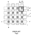
- FIG. 2 illustrates a plan layout view of memory cells in a conventional cross point memory.
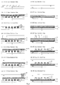
- Figs. 6(a), 6(b), 6(c), 6(d), 6(e), 6(f), and 6(g) are cross sectional views taken along the line A-A' and the line B-B' of Fig. 2 showing steps of a procedure of manufacturing the conventional memory cells.
- the procedure starts with, as shown in Fig. 6(a), depositing a BPSG layer 5 of 1500 nm thick on a silicon semiconductor substrate 4 accompanied with a memory circuit and polishing the same to a thickness of 1000 nm by a CMP (Chemical Mechanical Polishing) process to have a planar surface. Then, a contact plug 6 is provided for connecting between the silicon semiconductor substrate 4 and the lower electrodes 1. In succession, a sputtering process is conducted for depositing on the BPSG layer 5 a 50 nm thickness of TiN layer 7 which is made of a lower electrode material and turns to the lower electrodes 1 and a 150 nm thickness of Pt layer 8 on the TiN layer 7.
- a sputtering process is conducted for depositing on the BPSG layer 5 a 50 nm thickness of TiN layer 7 which is made of a lower electrode material and turns to the lower electrodes 1 and a 150 nm thickness of Pt layer 8 on the TiN layer 7.
- a photolithography process of providing a stripe, L/S (line and space) pattern of masking resist (not shown) for configuring the lower electrodes and dry etching both the TiN layer 7 and the Pt layer 8 to build the lower electrodes 1 after removal of the resist, as shown in Fig. 6(b).
- an SiO 2 layer 19 is deposited to a thickness of 500 nm by a CVD (Chemical Vapor Deposition) process and flattened by a CMP process to expose the surface of the Pt layer 8.
- CVD Chemical Vapor Deposition
- an SiO 2 layer 20 is deposited to a thickness of 300 nm on the SiO 2 layer 19 and the lower electrodes 1 (of the Pt layer 8) by a CVD process.
- Another lithography process follows for masking with a pattern of resists (not shown) which have an array of openings 3 for forming active layers at the intersections between the lower electrodes 1 and the upper electrodes 2.
- the SiO 2 layer 20 is dry etched at the openings to expose the Pt layer 8 for the active layers.
- a sputtering process follows for depositing on the Pt layer 8 and the SiO 2 layer 20 a Pr 0.7 Ca 0.3 MnO 3 (PCMO) layer 21 to a thickness of 200 nm which will turn to the perovskite memory materials as shown in Fig. 6(d).
- the PCMO layer 21 is then polished by a CMP process to expose the SiO 2 layer 20 and then a Pt layer 22 is deposited to a thickness of 100 nm by a sputtering process which will turn to the upper electrodes 2.
- an SiO 2 layer 14 is deposited to a thickness of 1200 nm on the Pt layer 22 by a CVD process and polished to a thickness of 800 nm by a CMP process to flatten the surface. Then, a pattern ofAl wiring 15 is provided for connecting between the Pt layer 22 of the upper electrodes 2 and the silicon semiconductor substrate 4, as shown in Fig. 6(g).
- each of the conventional methods disclosed in the publications requires a dedicated lithography step of providing a perovskite material at the intersection of the cross point structure.
- three lithography steps are needed as the dedicated step is added with the two essential steps for patterning the lower electrodes and the upper electrodes.
- the conventional cross point memory has each intersection between the upper electrode and the lower electrode determined as a memory cell. This area is crucial for determining the level of data density.
- the width of each of the lower electrodes 1 and the upper electrodes 2 will be greater than the minimum of the line width and the interval to be patterned by an applicable process or the minimum of the feasible size in the process.
- the margin is needed 0.5F at each side of the width of each of the lower electrodes 1 and the upper electrodes 2 and calculates a total of 2F.
- the present invention has been developed for eliminating the above drawback and its object is to provide a semiconductor memory device and a method for manufacturing the same where the memory cell area is reduced to a size smaller than the minimum of the size feasible in the conventional method and the number of lithography processing steps is minimized.
- a semiconductor memory device having a cross point structure which comprises a plurality of upper electrodes arranged to extend in one direction, a plurality of lower electrodes arrange to extend in another direction at a right angle to the direction of the upper electrodes, and an array of memory materials arranged between the upper electrodes and the lower electrodes for storage of data is particularly characterized in that the memory materials are made of a perovskite material and each of the memory materials is disposed at the lower electrodes side of the corresponding upper electrode extending along the corresponding upper electrode.
- the semiconductor memory device described above may preferably be modified in which the material of the lower electrodes contains a substance for encouraging the epitaxial growth of the perovskite material.
- the semiconductor memory device may more preferably be modified in which the material of the lower electrodes contains at least one selected from a platinum group of rare metals, a group of their alloys, an electrically conductive oxide group of Ir, Ru, Re, and Os, and another electrically conductive oxide group of SRO(SrRuO 3 ), LSCO((LaSr)CoO 3 ), and YBCO(YbBa 2 Cu 3 O 7 ).
- the semiconductor memory device may further preferably be modified in which the material of the upper electrodes contains at least one selected from a platinum group of rare metals, a group of metals Ag, Al, Cu, Ni, Ti, Ta, and their alloys, an electrically conductive oxide group of Ir, Ru, Re, and Os, and another electrically conductive oxide group of SRO(SrRuO 3 ), LSCO((LaSr)CoO 3 ), and YBCO(YbBa 2 Cu 3 O 7 ).
- a platinum group of rare metals a group of metals Ag, Al, Cu, Ni, Ti, Ta, and their alloys
- an electrically conductive oxide group of Ir, Ru, Re, and Os an electrically conductive oxide group of Ir, Ru, Re, and Os
- the semiconductor memory device may further preferably be modified in which the perovskite material is an oxide composed of at least one element selected from a group of Pr, Ca, La, Sr, Gd, Nd, Bi, Ba, Y, Ce, Pb, Sm, and Dy and at least one element selected from a group of Ta, Ti, Cu, Mn, Cr, Co, Fe, Ni, and Ga.
- the perovskite material is an oxide composed of at least one element selected from a group of Pr, Ca, La, Sr, Gd, Nd, Bi, Ba, Y, Ce, Pb, Sm, and Dy and at least one element selected from a group of Ta, Ti, Cu, Mn, Cr, Co, Fe, Ni, and Ga.
- the semiconductor memory device may further preferably be modified in which the perovskite material is an oxide expressed by at least one formula (where 0 ⁇ X ⁇ 1 and 0 ⁇ Z ⁇ 1) selected from Pr 1-X Ca X [Mn 1-Z M Z ]O 3 (where M is an element selected from a group of Cr, Co, Fe, Ni, and Ga), La 1-X AE X MnO 3 (where AE is a bivalent alkali earth metal selected from a group of Ca, Sr, Pb, and Ba), RE 1-X Sr X MnO 3 (where RE is a trivalent rare earth element selected from a group of Sm, La, Pr, Nd, Gd, and Dy), La 1-X Co X [Mn 1-Z Co Z ]O 3 , Gd 1-X Ca X MnO 3 , and Nd 1-X Gd X MnO 3 .
- the perovskite material is an oxide expressed by at least one formula (where 0 ⁇ X ⁇ 1 and
- a method for manufacturing the semiconductor memory device having a cross point structure described above comprises a first step of depositing in a succession on a semiconductor substrate the lower electrode material for lower electrodes and a surface protecting layer for protecting the surfaces of the lower electrodes, a second step of patterning the lower electrode material and the surface protecting layer with the use of a lower electrode masking to configure the lower electrodes, a third step of depositing a first insulating material on the lower electrodes and the surface protecting layer, a fourth step of flattening the first insulating material to expose the surface protecting layer, a fifth step of removing the surface protecting layer, a sixth step of depositing the memory material of a perovskite material on the lower electrodes and the first insulating material, a seventh step of depositing the upper electrode material for upper electrodes on the memory material, an eighth step of patterning the memory material and the upper electrode material with the use of an upper electrode masking to configure the upper electrodes, and a ninth step of depositing a second insulating
- a method of manufacturing the semiconductor memory device having a cross point structure described above comprises a first step of depositing on a semiconductor substrate the lower electrode material for lower electrodes, a second step of patterning the lower electrode material with the use of a lower electrode masking to configure the lower electrodes, a third step of depositing a first insulating material on the lower electrodes, a fourth step of flattening the first insulating material to expose the surfaces of the lower electrodes, a fifth step of depositing the memory material of a perovskite material on the lower electrodes and the first insulating material, a sixth step of depositing the upper electrode material for upper electrodes on the memory material, a seventh step of patterning the memory material and the upper electrode material with the use of an upper electrode masking to configure the upper electrodes, and an eighth step of depositing a second insulating material on the upper electrodes.
- a method of manufacturing the semiconductor memory device having a cross point structure described above comprises a first step of depositing on a semiconductor substrate a first insulating material, a second step of patterning the first insulating material with the use of a lower electrode masking, a third step of depositing the lower electrode material for lower electrodes on the first insulating material patterned at the second step, a fourth step of flattening the lower electrode material to expose the surface of the first insulating material and configure the lower electrodes, a fifth step of depositing the memory material of a perovskite material on the lower electrodes and the first insulating material, a sixth step of depositing the upper electrode material for upper electrodes on the memory material, a seventh step of patterning the memory material and the upper electrode material with the use of an upper electrode masking to configure the upper electrodes, and an eighth step of depositing a second insulating material on the upper electrodes.
- any one of the methods for manufacturing the semiconductor memory device described above may preferably be modified in which the step of pattering with the lower electrode masking includes a process of dry etching.
- any one of the methods for manufacturing the semiconductor memory device described above may more preferably be modified in which the step of flattening includes a process of chemical and mechanical polishing.
- any one of the methods for manufacturing the semiconductor memory device described above may further preferably be modified in which the step of pattering with the upper electrode masking includes a process of dry etching.
- any one of the methods for manufacturing the semiconductor memory device described above may further be characterized by a step of patterning a memory circuit prior to the step of depositing the perovskite material.
- the semiconductor memory device comprises, as shown in Fig. 1, a plurality of upper electrodes 2 arranged to extend in one direction, a plurality of lower electrodes 1 arranged to extend at a right angle to the one direction of the upper electrodes 2, and a group of memory materials provided between the upper electrodes 2 and the lower electrodes 1 for storage of data.
- the memory materials are made of a perovskite material and arranged at the lower electrodes 1 side of the corresponding upper electrodes 2 extending along the corresponding upper electrode 2.
- the memory materials are formed together with the upper electrodes 2 as their shape are identical to that of the upper electrodes 2.
- Fig. 1 is a plan layout view of the memory cells in the semiconductor memory device of the present invention.
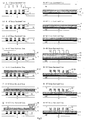
- Figs. 3(a), 3(b), 3(c), 3(d), 3(e), 3(f), and 3(g) are cross sectional views taken along the line A-A' and the line B-B' of Fig. 1 showing steps of the manufacturing procedure of the embodiment.
- the procedure starts with, as shown in Fig. 3(a), depositing a BPSG layer 5 of 1500 nm thick on a silicon semiconductor substrate 4 accompanied with a memory circuit and polishing the same to a thickness of 1000 nm by a CMP (Chemical Mechanical Polishing) process to have a planar surface. Then, a contact plug 6 is provided for connecting between the silicon semiconductor substrate 4 and the lower electrodes 1. In succession, a sputtering process is conducted for depositing on the BPSG layer 5 a 50 nm thickness of TiN layer 7 which is made of a lower electrode material and turns to the lower electrodes 1 and a 150 nm thickness of Pt layer 8 on the TiN layer 7.
- a sputtering process is conducted for depositing on the BPSG layer 5 a 50 nm thickness of TiN layer 7 which is made of a lower electrode material and turns to the lower electrodes 1 and a 150 nm thickness of Pt layer 8 on the TiN layer 7.
- the lower electrode material may be an electrically conductive oxide or any applicable conductive material.
- the electrically conductive lower electrode material contains YBa 2 Cu 3 O 7 (YBCO) for encouraging the epitaxial growth of perovskite.
- the electrically conductive lower electrode material may be platinum or iridium.
- the lower electrodes 1 are deposited to a thickness ranging substantially from 5 nm to 500 nm.
- an SiN layer 9 is deposited to a thickness of 150 nm by a CVD process, which acts as a surface protective layer on the electrode material (step 1).
- a photolithography process of providing a stripe, L/S (line and space) pattern of masking resist (not shown) for configuring the lower electrodes and dry etching the SiN layer 9, the Pt layer 8, and TiN layer 7 to build the lower electrodes 1 after removal of the resist (step 2).
- an SiO 2 layer 10 is deposited to a thickness of 600 nm on the lower electrodes 1 by CVD process (step 3).
- the insulating layer is not limited to the SiO 2 layer but may be selected from an SiN layer, a polyimide layer, an SiOF layer, and any other applicable insulating material layer.
- the insulating layer is deposited by any appropriate process such as pulsed laser deposition, rf sputtering, e-beam vapor deposition, thermal evaporation, organic metal deposition, spin-on deposition, or organic metal chemical vapor phase growth.
- the SiN 2 layer 10 is flattened by a CMP process to have the SiN layer 9 exposed at the top (step 4).
- the flattening action is not limited to the CMP process but may be selected from spin-on, a combination of spin-on and etching back, other applicable processes, and their combination.
- the SiN layer 9 is removed off with the use of heated phosphor, as shown in Fig. 3(c) (step 5).
- a sputtering process follows for depositing a Pr 0.7 Ca 0.3 MnO 3 (PCMO) layer 11 to a thickness of 100 nm which will turn to the perovskite memory materials (step 6).
- the perovskite material has a variable of resistivity which varies depending on the electric signal.
- the perovskite material is preferably selected from colossal magneto-resistant (CMR) materials and high-temperature super-conductive (HTSC) materials.
- CMR colossal magneto-resistant
- HTSC high-temperature super-conductive
- the perovskite material may be deposited by any appropriate process selected from pulsed laser deposition, rf sputtering, e-beam vapor deposition, thermal evaporation, organic metal deposition, sol-gel deposition, and organic metal chemical vapor phase growth. Then, a Pt layer 12 is deposited by a sputtering process on the PCMO layer 11, which will turn to the upper electrodes 2 (step 7). Pt is a preferable conductive material on the perovskite material. In this embodiment, the Pt layer 12 is deposited to a thickness of 100 nm. The thickness of the upper electrode material is substantially 5 nm to 500 nm.
- an SiO 2 layer 14 is deposited to a thickness of 1200 nm by a CVD process and polished to a thickness of 800 nm by a CMP process to flatten the surface (step 9). Then, a pattern of Al wiring 15 is provided for connecting between the upper electrodes 2 and the silicon semiconductor substrate 4, as shown in Fig. 3(g).
- the method of the first embodiment carries out the photolithography process two times for forming the cross points: the step of patterning the lower electrodes 1 (step 2) and the step of patterning the upper electrodes 2 (step 8). It is not necessary to provide the margins for positioning because the cross points are determined at the same time as of the patterning of the upper electrodes 2. Accordingly, once the minimum of the line width and the interval to be patterned by the applicable process or the minimum of the feasible size in the process has been determined as a unit pitch F, the lower electrodes 1 and the upper electrodes 2 are patterned at equal intervals of the unit pitch F as shown in Fig. 1.
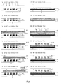
- Figs. 4(a), 4(b), 4(c), 4(d), 4(e), and 4(f) are cross sectional views taken along the line A-A' and the line B-B' of Fig. 1 showing steps of the manufacturing procedure of the embodiment.
- the procedure starts with, as shown in Fig. 4(a), depositing a BPSG layer 5 of 1500 nm thick on a silicon semiconductor substrate 4 accompanied with a memory circuit and polishing the same to a thickness of 1000 nm by a CMP process to have a planar surface. Then, a contact plug 6 is provided for connecting between the silicon semiconductor substrate 4 and the lower electrodes 1.
- a sputtering process is conducted for depositing on the BPSG layer 5 a 50 nm thickness of TiN layer 7 which is made of a lower electrode material and turns to the lower electrodes 1.
- a Pt layer 8 is deposited to a thickness of 150 nm on the TiN layer 7 by a sputtering process (step 1).
- the lower electrode material may be an electrically conductive oxide or any applicable conductive material equal to that of the first embodiment.
- the electrically conductive lower electrode material contains YBCO for encouraging the epitaxial growth of perovskite.
- the electrically conductive lower electrode material may be platinum or iridium.
- the lower electrodes 1 are deposited to a thickness ranging substantially from 5 nm to 500 nm.
- a photolithography process for providing a stripe, L/S (line and space) pattern of masking resist (not shown) for configuring the lower electrodes and dry etching the Pt layer 8 and the TiN layer 7 to build the lower electrodes 1 after removal of the resist (step 2).
- an SiO 2 layer 10 is deposited to a thickness of 600 nm on the lower electrodes 1 by CVD process (step 3).
- the insulating layer is not limited to the SiO 2 layer but may be selected from an SiN layer, a polyimide layer, an SiOF layer, and any other applicable insulating material layer.
- the insulating layer is deposited by any appropriate process such as pulsed laser deposition, rf sputtering, e-beam vapor deposition, thermal evaporation, organic metal deposition, spin-on deposition, or organic metal chemical vapor phase growth.
- the SiN 2 layer 10 is flattened by a CMP process to have the SiN layer 9 exposed at the top (step 4).
- the flattening action is not limited to the CMP process but may be selected from spin-on, a combination of spin-on and etching back, other applicable processes, and their combination.
- a sputtering process follows for depositing a perovskite PCMO layer 11 to a thickness of 100 nm (step 5).
- the perovskite material has a variable of resistivity which varies depending on the electric signal.
- the perovskite material is preferably selected from colossal magneto-resistant (CMR) materials and high-temperature super-conductive (HTSC) materials.
- CMR colossal magneto-resistant
- HTSC high-temperature super-conductive
- the perovskite material may be deposited by any appropriate process selected from pulsed laser deposition, rf sputtering, e-beam vapor deposition, thermal evaporation, organic metal deposition, sol-gel deposition, and organic metal chemical vapor phase growth. Then, a Pt layer 12 is deposited by a sputtering process on the PCMO layer 11, which will turn to the upper electrodes 2 (step 6). Pt is a preferable conductive material on the perovskite material. In this embodiment, the Pt layer 12 is deposited to a thickness of 100 nm. The thickness of the upper electrode material is substantially 5 nm to 500 nm.
- an SiO 2 layer 14 is deposited to a thickness of 1200 nm by a CVD process and polished to a thickness of 800 nm by a CMP process to flatten the surface (step 8). Then, a pattern of Al wiring 15 is provided for connecting between the upper electrodes 2 and the silicon semiconductor substrate 4, as shown in Fig. 4(f).
- the first embodiment causes the Pt layer 8 incorporating the lower electrodes 1 to generate a crystalline strain at the surface during the removal of the nitride layer of surface protective layer with the use of heated phosphor
- this embodiment is capable of attenuating the crystalline strain at the surface of the Pt layer 8.
- the method of the second embodiment carries out the photolithography process two times for forming the cross points: the step of patterning the lower electrodes 1 (step 2) and the step of patterning the upper electrodes 2 (step 7). Also, the lower electrodes 1 and the upper electrodes 2 are patterned at equal intervals of the unit pitch F as shown in Fig. 1.
- Figs. 5(a), 5(b), 5(c), 5(d), 5(e), 5(f), and 5(g) are cross sectional views taken along the line A-A' and the line B-B' of Fig. 1 showing steps of the manufacturing procedure of the embodiment.
- the procedure starts with depositing a BPSG layer 5 of 1500 nm thick on a silicon semiconductor substrate 4 accompanied with a memory circuit and polishing the same to a thickness of 1000 nm by a CMP process to have a planar surface. Then, a contact plug 6 is provided for connecting between the silicon semiconductor substrate 4 and the lower electrodes 1. In succession, a CVD process is conducted for depositing on the BPSG layer 5 a 200 nm thickness of SiO 2 layer 16 (step 1).
- the insulating layer is not limited to the SiO 2 layer but may be selected from an SiN layer, a polyimide layer, an SiOF layer, and any other applicable insulating material layer.
- the insulating layer is deposited by any appropriate process such as pulsed laser deposition, rf sputtering, e-beam vapor deposition, thermal evaporation, organic metal deposition, spin-on deposition, or organic metal chemical vapor phase growth. Then, using a photolithography process, a stripe, L/S (line and space) pattern of masking resist (not shown) for configuring the lower electrodes is provided and a dry etching process follows for etching the SiO 2 layer 16 to expose the lower electrodes 1 area of the SiO 2 layer 16 as shown in Fig. 5(a) (step 2).
- the lower electrode material may be an electrically conductive oxide or any applicable conductive material.
- the electrically conductive lower electrode material contains YBCO for encouraging the epitaxial growth of perovskite.
- the electrically conductive lower electrode material may be platinum or iridium.
- the TiN layer 17 and the Pt layer 18 are flattened by a CMP process to have the SiO 2 layer 16 exposed at the top thus patterning the lower electrodes 1 (step 4).
- the flattening action is not limited to the CMP process but may be selected from spin-on, a combination of spin-on and etching back, other applicable processes, and their combination.
- the Pt layer 18 turning to the lower electrodes 1 after the CMP process is deposited to a thickness ranging substantially from 5 nm to 500 nm.
- a sputtering process follows for depositing a PCMO layer 11 to a thickness of 100 nm which will turn to the perovskite memory materials (step 5).
- the perovskite material has a variable of resistivity which varies depending on the electric signal.
- the perovskite material is preferably selected from colossal magneto-resistant (CMR) materials and high-temperature super-conductive (HTSC) materials.
- CMR colossal magneto-resistant
- HTSC high-temperature super-conductive
- the perovskite material may be deposited by any appropriate process selected from pulsed laser deposition, rf sputtering, e-beam vapor deposition, thermal evaporation, organic metal deposition, sol-gel deposition, and organic metal chemical vapor phase growth. Then, a Pt layer 12 is deposited by a sputtering process on the PCMO layer 11, which will turn to the upper electrodes 2 (step 6). Pt is a preferable conductive material on the perovskite material. In this embodiment, the Pt layer 12 is deposited to a thickness of 100 nm. The thickness of the upper electrode material is substantially 5 nm to 500 nm.
- an SiO 2 layer 14 is deposited to a thickness of 1200 nm by a CVD process and polished to a thickness of 800 nm by a CMP process to flatten the surface (step 8). Then, a pattern of Al wiring 15 is provided for connecting between the upper electrodes 2 and the silicon semiconductor substrate 4, as shown in Fig. 5(g).
- the method of the third embodiment carries out the photolithography process two times for forming the cross points: the step of patterning the lower electrodes 1 (step 2) and the step of patterning the upper electrodes 2 (step 7). Since the lower electrodes 1 and the upper electrodes 2 are patterned at equal intervals of the unit pitch F as shown in Fig. 1.
- the third embodiment employs a dry etching process for removing the oxide layer to pattern the lower electrodes 1 and will thus be more favorable in the miniaturization of arrangement than the first and second embodiments where the patterning of the lower electrodes 1 is conducted through dry etching the Pt layer.
- the method of the present invention allows the active layer (of memory cells) to be deposited through self-aligning with the upper electrodes 2, whereby the number of steps for the photolithography process can be reduced from three, which is essential for the prior art, to two. Also, while the cell area in the prior art is as large as 9 F 2 , the method for the present invention can decrease the cell area to 4F 2 .
- the electrically conductive material used for developing the lower electrodes 1 contains, but is not limited to, either YBCO, platinum, or iridium in the first to third embodiments, it may contain at least one selected from a group of platinum based alloys, a electrically conductive oxide group of Ru, Re, and Os, and another electrically conductive oxide group of SRO(SrRuO 3 ) and LSCO((LaSr)CoO 3 ).
- the perovskite material is PCMO in the first to third embodiments, it may be either an oxide composed of at least one element selected from a group of Pr, Ca, La, Sr, Gd, Nd, Bi, Ba, Y, Ce, Pb, Sm, and Dy and at least one element selected from a group of Ta, Ti, Cu, Mn, Cr, Co, Fe, Ni, and Ga or another oxide expressed by at least one formula (where 0 ⁇ X ⁇ 1 and 0 ⁇ Z ⁇ 1) selected from Pr 1-X Ca X [Mn 1-Z M Z ]O 3 (where M is an element selected from a group of Cr, Co, Fe, Ni, and Ga), La 1-X AE X MnO 3 (where AE is a bivalent alkali earth metal selected from a group of Ca, Sr, Pb, and Ba), RE 1-X Sr X MnO 3 (where RE is a trivalent rare earth element selected from a group of Sm, La, Pr, Nd, Gd, and Dy
- the upper electrode material is, but not limited to, a Pt material in the first to third embodiments, it may contain, with equal success, at least one selected from a platinum group of rare metals, a group of metals Ag, Al, Cu, Ni, Ti, Ta, and their alloys, an electrically conductive oxide group of Ir, Ru, Re, and Os, and another electrically conductive oxide group of SRO(SrRuO 3 ), LSCO((LaSr)CoO 3 ), and YBCO(YbBa 2 Cu 3 O 7 ).
- a platinum group of rare metals a group of metals Ag, Al, Cu, Ni, Ti, Ta, and their alloys
- an electrically conductive oxide group of Ir, Ru, Re, and Os an electrically conductive oxide group of Ir, Ru, Re, and Os
- a step of patterning a memory circuit prior to the step of depositing the perovskite material may be provided.
Landscapes
- Engineering & Computer Science (AREA)
- Chemical & Material Sciences (AREA)
- Materials Engineering (AREA)
- Manufacturing & Machinery (AREA)
- Semiconductor Memories (AREA)
- Hall/Mr Elements (AREA)
Applications Claiming Priority (1)
| Application Number | Priority Date | Filing Date | Title |
|---|---|---|---|
| JP2004333130A JP4880894B2 (ja) | 2004-11-17 | 2004-11-17 | 半導体記憶装置の構造及びその製造方法 |
Publications (2)
| Publication Number | Publication Date |
|---|---|
| EP1659593A2 true EP1659593A2 (de) | 2006-05-24 |
| EP1659593A3 EP1659593A3 (de) | 2007-08-01 |
Family
ID=35840600
Family Applications (1)
| Application Number | Title | Priority Date | Filing Date |
|---|---|---|---|
| EP05024108A Withdrawn EP1659593A3 (de) | 2004-11-17 | 2005-11-04 | Vorrichtung und Verfahren zur Herstellung eines Kreuzpunkt-Speichers |
Country Status (6)
| Country | Link |
|---|---|
| US (2) | US7879626B2 (de) |
| EP (1) | EP1659593A3 (de) |
| JP (1) | JP4880894B2 (de) |
| KR (1) | KR100796537B1 (de) |
| CN (1) | CN100442519C (de) |
| TW (1) | TWI292216B (de) |
Cited By (4)
| Publication number | Priority date | Publication date | Assignee | Title |
|---|---|---|---|---|
| WO2010005862A1 (en) * | 2008-07-09 | 2010-01-14 | Sandisk 3D Llc | Cross point memory cells with shared diodes and method of making same |
| US7910407B2 (en) | 2008-12-19 | 2011-03-22 | Sandisk 3D Llc | Quad memory cell and method of making same |
| US7923812B2 (en) | 2008-12-19 | 2011-04-12 | Sandisk 3D Llc | Quad memory cell and method of making same |
| US8014185B2 (en) | 2008-07-09 | 2011-09-06 | Sandisk 3D Llc | Multiple series passive element matrix cell for three-dimensional arrays |
Families Citing this family (22)
| Publication number | Priority date | Publication date | Assignee | Title |
|---|---|---|---|---|
| US6962648B2 (en) * | 2003-09-15 | 2005-11-08 | Global Silicon Net Corp. | Back-biased face target sputtering |
| US20060081467A1 (en) * | 2004-10-15 | 2006-04-20 | Makoto Nagashima | Systems and methods for magnetron deposition |
| US20060081466A1 (en) * | 2004-10-15 | 2006-04-20 | Makoto Nagashima | High uniformity 1-D multiple magnet magnetron source |
| US7425504B2 (en) * | 2004-10-15 | 2008-09-16 | 4D-S Pty Ltd. | Systems and methods for plasma etching |
| US8395199B2 (en) | 2006-03-25 | 2013-03-12 | 4D-S Pty Ltd. | Systems and methods for fabricating self-aligned memory cell |
| US8454810B2 (en) * | 2006-07-14 | 2013-06-04 | 4D-S Pty Ltd. | Dual hexagonal shaped plasma source |
| US7932548B2 (en) | 2006-07-14 | 2011-04-26 | 4D-S Pty Ltd. | Systems and methods for fabricating self-aligned memory cell |
| US20080011603A1 (en) * | 2006-07-14 | 2008-01-17 | Makoto Nagashima | Ultra high vacuum deposition of PCMO material |
| US8308915B2 (en) | 2006-09-14 | 2012-11-13 | 4D-S Pty Ltd. | Systems and methods for magnetron deposition |
| JP4577695B2 (ja) * | 2006-11-07 | 2010-11-10 | エルピーダメモリ株式会社 | 半導体記憶装置及び半導体記憶装置の製造方法 |
| WO2010026663A1 (ja) * | 2008-09-08 | 2010-03-11 | 株式会社 東芝 | 不揮発性記憶素子及び不揮発性記憶装置 |
| WO2010095296A1 (ja) | 2009-02-20 | 2010-08-26 | 株式会社村田製作所 | 抵抗記憶素子およびその使用方法 |
| WO2010095295A1 (ja) | 2009-02-20 | 2010-08-26 | 株式会社村田製作所 | 抵抗記憶素子およびその使用方法 |
| JP2011238828A (ja) * | 2010-05-12 | 2011-11-24 | Nec Corp | 半導体装置及びその製造方法 |
| KR20150145631A (ko) * | 2014-06-20 | 2015-12-30 | 에스케이하이닉스 주식회사 | 크로스 포인트 어레이를 구비하는 반도체 장치의 제조 방법 |
| KR101682519B1 (ko) | 2015-06-26 | 2016-12-07 | 주식회사 티케이씨 | 도금설비의 아노드 장치 |
| CN108091759B (zh) * | 2016-11-23 | 2019-07-09 | 清华大学 | 相变电子器件 |
| CN108091870B (zh) | 2016-11-23 | 2021-02-26 | 清华大学 | 含氢过渡金属氧化物、制备方法及原电池 |
| CN108091760B (zh) | 2016-11-23 | 2019-11-22 | 清华大学 | 调控含氢过渡金属氧化物相变的方法 |
| CN108091913B (zh) | 2016-11-23 | 2020-01-21 | 清华大学 | 固态燃料电池及固态电解质的制备方法 |
| KR102047093B1 (ko) | 2017-11-16 | 2019-11-21 | 주식회사 티케이씨 | 인쇄회로기판의 도금편차 개선을 위한 지그장치 |
| KR20200030651A (ko) | 2018-09-12 | 2020-03-23 | 주식회사 티케이씨 | 인쇄회로기판용 개별 전기 도금장치 |
Citations (2)
| Publication number | Priority date | Publication date | Assignee | Title |
|---|---|---|---|---|
| US20020098281A1 (en) * | 2001-01-24 | 2002-07-25 | Ning Xian J. | Self-aligned conductive line for cross-point magnetic memory integrated circuits |
| US20030206481A1 (en) * | 2001-06-28 | 2003-11-06 | Hsu Sheng Teng | Trench isolated cross-point memory array and method of fabrication |
Family Cites Families (40)
| Publication number | Priority date | Publication date | Assignee | Title |
|---|---|---|---|---|
| JPH0775247B2 (ja) * | 1990-05-28 | 1995-08-09 | 株式会社東芝 | 半導体記憶装置 |
| JPH11330411A (ja) * | 1998-05-13 | 1999-11-30 | Matsushita Electric Ind Co Ltd | 半導体記憶装置及びその製造方法 |
| JP4068781B2 (ja) * | 2000-02-28 | 2008-03-26 | 株式会社ルネサステクノロジ | 半導体集積回路装置および半導体集積回路装置の製造方法 |
| JP3940883B2 (ja) * | 2000-09-18 | 2007-07-04 | セイコーエプソン株式会社 | 強誘電体メモリ装置の製造方法 |
| US6958508B2 (en) * | 2000-10-17 | 2005-10-25 | Matsushita Electric Industrial Co., Ltd. | Ferroelectric memory having ferroelectric capacitor insulative film |
| US6611453B2 (en) * | 2001-01-24 | 2003-08-26 | Infineon Technologies Ag | Self-aligned cross-point MRAM device with aluminum metallization layers |
| JP3853163B2 (ja) * | 2001-02-20 | 2006-12-06 | 松下電器産業株式会社 | 強誘電体メモリ装置及びその製造方法 |
| US6919633B2 (en) * | 2001-03-07 | 2005-07-19 | Hewlett-Packard Development Company, L.P. | Multi-section foldable memory device |
| US6646912B2 (en) * | 2001-06-05 | 2003-11-11 | Hewlett-Packard Development Company, Lp. | Non-volatile memory |
| US6552409B2 (en) * | 2001-06-05 | 2003-04-22 | Hewlett-Packard Development Company, Lp | Techniques for addressing cross-point diode memory arrays |
| JP2002368200A (ja) * | 2001-06-08 | 2002-12-20 | Sony Corp | 半導体記憶装置 |
| US6927430B2 (en) * | 2001-06-28 | 2005-08-09 | Sharp Laboratories Of America, Inc. | Shared bit line cross-point memory array incorporating P/N junctions |
| US6693821B2 (en) | 2001-06-28 | 2004-02-17 | Sharp Laboratories Of America, Inc. | Low cross-talk electrically programmable resistance cross point memory |
| US6569745B2 (en) * | 2001-06-28 | 2003-05-27 | Sharp Laboratories Of America, Inc. | Shared bit line cross point memory array |
| US6531371B2 (en) * | 2001-06-28 | 2003-03-11 | Sharp Laboratories Of America, Inc. | Electrically programmable resistance cross point memory |
| US6759249B2 (en) * | 2002-02-07 | 2004-07-06 | Sharp Laboratories Of America, Inc. | Device and method for reversible resistance change induced by electric pulses in non-crystalline perovskite unipolar programmable memory |
| JP2003243622A (ja) * | 2002-02-19 | 2003-08-29 | Seiko Epson Corp | 強誘電体キャパシタを有するメモリセルアレイおよびその製造方法 |
| US6534326B1 (en) * | 2002-03-13 | 2003-03-18 | Sharp Laboratories Of America, Inc. | Method of minimizing leakage current and improving breakdown voltage of polycrystalline memory thin films |
| JP2003282838A (ja) * | 2002-03-27 | 2003-10-03 | Seiko Epson Corp | 強誘電体キャパシタおよびその製造方法、メモリセルアレイ、誘電体キャパシタの製造方法、ならびに、メモリ装置 |
| JP3680035B2 (ja) * | 2002-03-29 | 2005-08-10 | 株式会社東芝 | 磁気記録装置及び磁気記録方法 |
| US6798685B2 (en) * | 2002-08-02 | 2004-09-28 | Unity Semiconductor Corporation | Multi-output multiplexor |
| US6583003B1 (en) * | 2002-09-26 | 2003-06-24 | Sharp Laboratories Of America, Inc. | Method of fabricating 1T1R resistive memory array |
| US6746910B2 (en) * | 2002-09-30 | 2004-06-08 | Sharp Laboratories Of America, Inc. | Method of fabricating self-aligned cross-point memory array |
| US6875651B2 (en) * | 2003-01-23 | 2005-04-05 | Sharp Laboratories Of America, Inc. | Dual-trench isolated crosspoint memory array and method for fabricating same |
| US6977402B2 (en) * | 2003-03-25 | 2005-12-20 | Sanyo Electric Co., Ltd. | Memory device having storage part and thin-film part |
| JP2004303988A (ja) * | 2003-03-31 | 2004-10-28 | Seiko Epson Corp | 半導体記憶装置及びその製造方法 |
| JP2004356458A (ja) * | 2003-05-30 | 2004-12-16 | Seiko Epson Corp | 半導体集積回路装置及びその製造方法 |
| US7009278B2 (en) * | 2003-11-24 | 2006-03-07 | Sharp Laboratories Of America, Inc. | 3d rram |
| US7095644B2 (en) * | 2003-12-22 | 2006-08-22 | Unity Semiconductor Corporation | Conductive memory array having page mode and burst mode read capability |
| JP2005244145A (ja) * | 2004-01-28 | 2005-09-08 | Sharp Corp | 半導体記憶装置及びその製造方法 |
| US7082052B2 (en) * | 2004-02-06 | 2006-07-25 | Unity Semiconductor Corporation | Multi-resistive state element with reactive metal |
| JP2005243808A (ja) * | 2004-02-25 | 2005-09-08 | Sharp Corp | 半導体素子の製造方法 |
| US20050230724A1 (en) * | 2004-04-16 | 2005-10-20 | Sharp Laboratories Of America, Inc. | 3D cross-point memory array with shared connections |
| US7038231B2 (en) * | 2004-04-30 | 2006-05-02 | International Business Machines Corporation | Non-planarized, self-aligned, non-volatile phase-change memory array and method of formation |
| JP4377751B2 (ja) * | 2004-06-10 | 2009-12-02 | シャープ株式会社 | クロスポイント構造の半導体記憶装置及びその製造方法 |
| JP2006032728A (ja) * | 2004-07-16 | 2006-02-02 | Matsushita Electric Ind Co Ltd | 不揮発性メモリ |
| US7075817B2 (en) * | 2004-07-20 | 2006-07-11 | Unity Semiconductor Corporation | Two terminal memory array having reference cells |
| JP2006120702A (ja) * | 2004-10-19 | 2006-05-11 | Matsushita Electric Ind Co Ltd | 可変抵抗素子および半導体装置 |
| KR100593750B1 (ko) * | 2004-11-10 | 2006-06-28 | 삼성전자주식회사 | 이성분계 금속 산화막을 데이터 저장 물질막으로 채택하는교차점 비휘발성 기억소자 및 그 제조방법 |
| US7488967B2 (en) * | 2005-04-06 | 2009-02-10 | International Business Machines Corporation | Structure for confining the switching current in phase memory (PCM) cells |
-
2004
- 2004-11-17 JP JP2004333130A patent/JP4880894B2/ja not_active Expired - Fee Related
-
2005
- 2005-11-02 TW TW094138441A patent/TWI292216B/zh not_active IP Right Cessation
- 2005-11-04 EP EP05024108A patent/EP1659593A3/de not_active Withdrawn
- 2005-11-15 KR KR1020050109206A patent/KR100796537B1/ko not_active Expired - Fee Related
- 2005-11-16 US US11/274,258 patent/US7879626B2/en not_active Expired - Fee Related
- 2005-11-17 CN CNB2005101254839A patent/CN100442519C/zh not_active Expired - Fee Related
-
2010
- 2010-12-22 US US12/976,113 patent/US8030695B2/en not_active Expired - Lifetime
Patent Citations (2)
| Publication number | Priority date | Publication date | Assignee | Title |
|---|---|---|---|---|
| US20020098281A1 (en) * | 2001-01-24 | 2002-07-25 | Ning Xian J. | Self-aligned conductive line for cross-point magnetic memory integrated circuits |
| US20030206481A1 (en) * | 2001-06-28 | 2003-11-06 | Hsu Sheng Teng | Trench isolated cross-point memory array and method of fabrication |
Cited By (5)
| Publication number | Priority date | Publication date | Assignee | Title |
|---|---|---|---|---|
| WO2010005862A1 (en) * | 2008-07-09 | 2010-01-14 | Sandisk 3D Llc | Cross point memory cells with shared diodes and method of making same |
| US7733685B2 (en) | 2008-07-09 | 2010-06-08 | Sandisk 3D Llc | Cross point memory cell with distributed diodes and method of making same |
| US8014185B2 (en) | 2008-07-09 | 2011-09-06 | Sandisk 3D Llc | Multiple series passive element matrix cell for three-dimensional arrays |
| US7910407B2 (en) | 2008-12-19 | 2011-03-22 | Sandisk 3D Llc | Quad memory cell and method of making same |
| US7923812B2 (en) | 2008-12-19 | 2011-04-12 | Sandisk 3D Llc | Quad memory cell and method of making same |
Also Published As
| Publication number | Publication date |
|---|---|
| TW200631163A (en) | 2006-09-01 |
| US20060102943A1 (en) | 2006-05-18 |
| CN100442519C (zh) | 2008-12-10 |
| US8030695B2 (en) | 2011-10-04 |
| US20110089395A1 (en) | 2011-04-21 |
| EP1659593A3 (de) | 2007-08-01 |
| CN1776912A (zh) | 2006-05-24 |
| US7879626B2 (en) | 2011-02-01 |
| TWI292216B (en) | 2008-01-01 |
| JP2006147694A (ja) | 2006-06-08 |
| KR100796537B1 (ko) | 2008-01-21 |
| JP4880894B2 (ja) | 2012-02-22 |
| KR20060055363A (ko) | 2006-05-23 |
Similar Documents
| Publication | Publication Date | Title |
|---|---|---|
| US8030695B2 (en) | Structure and manufacturing method of semiconductor memory device | |
| CN101432879B (zh) | 可变电阻元件及其制造方法 | |
| KR101147945B1 (ko) | 가변 저항 소자 및 그 제조 방법 | |
| US7439082B2 (en) | Conductive memory stack with non-uniform width | |
| US7186569B2 (en) | Conductive memory stack with sidewall | |
| US7602026B2 (en) | Memory cell, semiconductor memory device, and method of manufacturing the same | |
| KR100593750B1 (ko) | 이성분계 금속 산화막을 데이터 저장 물질막으로 채택하는교차점 비휘발성 기억소자 및 그 제조방법 | |
| US20050230724A1 (en) | 3D cross-point memory array with shared connections | |
| US7692178B2 (en) | Nonvolatile memory element, nonvolatile memory apparatus, and method of manufacture thereof | |
| US20060154417A1 (en) | Semiconductor memory device | |
| KR20100083402A (ko) | 저항 메모리 장치 및 그 제조방법 | |
| JP4939324B2 (ja) | 可変抵抗素子及びその製造方法 | |
| JP4238248B2 (ja) | 可変抵抗素子を備えた不揮発性半導体記憶装置の製造方法 | |
| JP2006344876A (ja) | 不揮発性記憶素子とその製造方法 |
Legal Events
| Date | Code | Title | Description |
|---|---|---|---|
| PUAI | Public reference made under article 153(3) epc to a published international application that has entered the european phase |
Free format text: ORIGINAL CODE: 0009012 |
|
| AK | Designated contracting states |
Kind code of ref document: A2 Designated state(s): AT BE BG CH CY CZ DE DK EE ES FI FR GB GR HU IE IS IT LI LT LU LV MC NL PL PT RO SE SI SK TR |
|
| AX | Request for extension of the european patent |
Extension state: AL BA HR MK YU |
|
| PUAL | Search report despatched |
Free format text: ORIGINAL CODE: 0009013 |
|
| AK | Designated contracting states |
Kind code of ref document: A3 Designated state(s): AT BE BG CH CY CZ DE DK EE ES FI FR GB GR HU IE IS IT LI LT LU LV MC NL PL PT RO SE SI SK TR |
|
| AX | Request for extension of the european patent |
Extension state: AL BA HR MK YU |
|
| 17P | Request for examination filed |
Effective date: 20071123 |
|
| 17Q | First examination report despatched |
Effective date: 20071227 |
|
| AKX | Designation fees paid |
Designated state(s): DE FR GB IT |
|
| STAA | Information on the status of an ep patent application or granted ep patent |
Free format text: STATUS: THE APPLICATION IS DEEMED TO BE WITHDRAWN |
|
| 18D | Application deemed to be withdrawn |
Effective date: 20090123 |