EP1659823B1 - Suspension pour haut-parleur - Google Patents
Suspension pour haut-parleur Download PDFInfo
- Publication number
- EP1659823B1 EP1659823B1 EP05110837A EP05110837A EP1659823B1 EP 1659823 B1 EP1659823 B1 EP 1659823B1 EP 05110837 A EP05110837 A EP 05110837A EP 05110837 A EP05110837 A EP 05110837A EP 1659823 B1 EP1659823 B1 EP 1659823B1
- Authority
- EP
- European Patent Office
- Prior art keywords
- grooves
- curvature
- suspension structure
- surround
- radius
- Prior art date
- Legal status (The legal status is an assumption and is not a legal conclusion. Google has not performed a legal analysis and makes no representation as to the accuracy of the status listed.)
- Expired - Lifetime
Links
Images


Classifications
-
- H—ELECTRICITY
- H04—ELECTRIC COMMUNICATION TECHNIQUE
- H04R—LOUDSPEAKERS, MICROPHONES, GRAMOPHONE PICK-UPS OR LIKE ACOUSTIC ELECTROMECHANICAL TRANSDUCERS; ELECTRIC HEARING AIDS; PUBLIC ADDRESS SYSTEMS
- H04R7/00—Diaphragms for electromechanical transducers; Cones
- H04R7/16—Mounting or tensioning of diaphragms or cones
- H04R7/18—Mounting or tensioning of diaphragms or cones at the periphery
- H04R7/20—Securing diaphragm or cone resiliently to support by flexible material, springs, cords, or strands
-
- H—ELECTRICITY
- H04—ELECTRIC COMMUNICATION TECHNIQUE
- H04R—LOUDSPEAKERS, MICROPHONES, GRAMOPHONE PICK-UPS OR LIKE ACOUSTIC ELECTROMECHANICAL TRANSDUCERS; ELECTRIC HEARING AIDS; PUBLIC ADDRESS SYSTEMS
- H04R9/00—Transducers of moving-coil, moving-strip, or moving-wire type
- H04R9/02—Details
- H04R9/04—Construction, mounting, or centering of coil
- H04R9/041—Centering
- H04R9/043—Inner suspension or damper, e.g. spider
-
- H—ELECTRICITY
- H04—ELECTRIC COMMUNICATION TECHNIQUE
- H04R—LOUDSPEAKERS, MICROPHONES, GRAMOPHONE PICK-UPS OR LIKE ACOUSTIC ELECTROMECHANICAL TRANSDUCERS; ELECTRIC HEARING AIDS; PUBLIC ADDRESS SYSTEMS
- H04R2307/00—Details of diaphragms or cones for electromechanical transducers, their suspension or their manufacture covered by H04R7/00 or H04R31/003, not provided for in any of its subgroups
- H04R2307/207—Shape aspects of the outer suspension of loudspeaker diaphragms
Definitions
- This invention relates to loudspeaker suspensions, including surrounds and spiders.
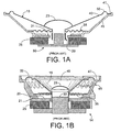
- a typical loudspeaker 14 includes a stiff cone 15 connected to a voice coil 20 at the apex of the cone.
- the loudspeaker can include a dust cap 23 attached to the cone.
- the voice coil 20 interacts with the magnetic circuit formed from permanent magnet 25, back plate/pole piece structure 30, and top plate 21. When the voice coil is driven by an audio signal, the cone vibrates axially to produce sound.
- An outer edge 40 of the cone is attached to a rigid basket 45 along an annular mounting flange 47 by suspension element 50, typically referred to as a surround.
- the voice coil 20 and/or apex of cone 15 may be attached to another section of the rigid basket 45 by second suspension element 35, typically referred to as a spider.
- the surround 50 is often made from a flexible material, such as fabric, that allows the cone to vibrate but provides a restoring force to aide in returning the cone to an at-rest position, when the voice coil 20 is not being driven.
- the spider 35 typically is a circular woven cloth part with concentric corrugations.
- the suspension elements provide a restoring force (along the axial direction) and a centering force (along the radial direction) for the moving assembly.
- Single or multiple surrounds and/or spiders may be used in various transducer embodiments.
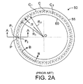
- prior art surround 50 can be seen to be a hollow semi-toroid about a center O with an inner circumferential edge 60 and an outer circumferential edge 55.
- surround 50 is depicted as having a semicircular or dome shaped cross-section taken along line A-A of FIG. 2A
- FIG. 4 shows a plan view of an alternative prior art surround configuration.
- FIG. 5 shows a circumferential section along line B-B of FIG. 3 .
- the example surround in FIG. 4 has grooves 65 extending outward at an angle to the radial direction, over the majority of the span from the inner to the outer circumferential edges of the surround.
- Each groove has a V-shaped trough D at the bottom and folded corners E, F at the top.
- US 2003/231784 A discloses a loudspeaker surround which includes grooves extending across the surround at an angle to the radius of the surround, the surface of the surround being otherwise flat.
- the invention features an apparatus that includes: a loudspeaker suspension structure having an inner circumferential border, and an outer circumferential border, and grooves each extending from the inner circumferential border to the outer circumferential border at an angle with respect to a normal to the inner circumferential border, a profile of a circumferential section of the suspension structure which is continuously curved.
- Implementations may include one or more of the following features.
- the groove spans only a portion of the distance between the inner circumferential border and the outer circumferential border.
- the continuous curvature is cyclical.
- the continuous curvature includes a series of peaks and grooves and the radius of curvature of each of the peaks is greater than the radiuses of curvature of the adjacent grooves.
- the continuous curvature includes a series of peaks and grooves and the radius of curvature of at least a portion of each of the peaks is less than (or in other examples greater than) the radiuses of curvature of the adjacent grooves.
- the ratio of the radius of curvature of each of the peaks to the radiuses of curvature of the adjacent grooves is less than 3 (or less than 5 or less than 10).
- the suspension structure comprises a fractional part of a toroid.
- the suspension structure conforms to a rolled shape.
- the rolled shape is rolled up.
- the rolled shape is rolled down.
- the rolled shape comprises two or more rolls between the inner circumferential border and the outer circumferential border.
- a radius of curvature of each of the grooves is at least about three times a thickness of a material of which the suspension structure is formed.
- a radius of curvature of each of the grooves is at least about seven times a thickness of a material of which the suspension structure is formed.
- Grooves are spaced regularly along a circumference of the suspension structure, each of the grooves has a depth, and a pitch of the spacing is at least about four times the depth.
- the grooves are straight in plan view.
- the angle of the straight grooves is in the range of 10 to 80 degrees.
- Each of the grooves comprises a curve in plan view.
- the angle of the curved grooves is in the range of 0 to 80 degrees.
- the curve begins at an angle to the normal to the inner circumferential border or the outer circumferential border.
- the curve comprises sections.
- the sections comprise straight sections or curved sections.
- the sections have respectively different angles with respect to the normal to the inner border.
- the sections also comprise transition sections that smoothly the straight or curved sections.
- the sections meet at inflection points.
- Each of the grooves has a depth that varies from the inner border to the outer border.
- the variation corresponds to the variation in height of a principal contour of the suspension structure.
- the groove has a larger radius of curvature than does the principal contour.
- Each of the grooves has a generally constant depth along most of a path of the groove.
- the groove includes two or more local minima or maxima.
- a radial cross section of the suspension structure has a configuration of a partial toroid.
- a radial cross section of the suspension structure has a configuration other than of a partial toroid.
- a radial cross section of the suspension structure has two or more local minima or maxima.
- the continuous curvature comprises a piecewise linear contour.
- the suspension structure comprises a surround.
- the suspension structure comprises a spider.
- a semi-toroidal surround suspension element 100 is centered about an origin O and includes an inner circumferential edge 105 and an outer circumferential edge 110, separated by a radial width or span W.
- the surround 100 can include an inner attachment flange 115 extending radially inward from the inner circumferential edge 105 and an outer attachment flange 120 extending radially outward from the outer circumferential edge 110 for connection to the cone and basket, respectively.
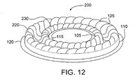
- the surround 100 can also include a loudspeaker spider, an example of which is shown in FIG 12 . Surround 100 in FIGS.
- a convolution as the term is used herein, comprises one cycle of a possibly repeating structure, where the structure is typically comprised of concatenated sections of arcs.
- the arcs are generally circular, but can have any curvature.
- Spider 200 in FIG. 12 includes multiple (two in this case) convolutions 220, 230. In other spider embodiments, more or fewer convolutions, or portions of convolutions, may be used.
- surround 100 in FIGS. 6A - 6C is depicted as a partial toroidal section, other less axially symmetrical shapes for attachment to non-circular cones (e.g. elliptical, racetrack, or other non-circular shapes) are contemplated.
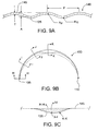
- a circumferential section A-A is shown in FIG. 9A . This section is taken at a constant normal distance to the inner edge of the surround suspension element. For a surround with a circular geometry, this section will trace out a circle.
- a similar section for a surround with a non circular geometry is also understood to be taken at a constant normal distance from the inner edge, but the path traced around the surround for such embodiments would no longer be circular.
- circumferential section to encompass cases of both circular and non circular surround geometries, where the section is taken at a constant normal distance from the inner suspension element edge.
- a radial section B-B is shown in FIG. 9B .
- This section is taken normal to the inner edge of the surround suspension element.
- this section will also coincide with a radial direction.
- a similar section for a surround with a non-circular geometry is understood to be taken normal to the inner edge, but in this case the section may no longer correspond to a radius.
- radial section to mean a section taken normal to the inner edge of the suspension element, and to encompass cases of both circular and non-circular suspension element geometries.
- nominal shapes other than half-circular are also contemplated.
- some embodiments may have radial cross sections comprised of concatenated sections of circular arcs, as would be typical of multi-roll surrounds or spiders, or have undulations along nominally circular arcs or arc sections, as shown in the example of FIG. 13 .
- Another cross section (not shown) may look like a typical half roll, but with the side walls deepended to increase the effective roll height.
- These radial profiles can be used in toroidal shaped surrounds as depicted in FIGS. 6A - 6C , or other less axially symmetrical shapes (e.g. elliptical, oval or racetrack, or other non-circular shapes).
- the surround 100 includes a series of grooves 125 generally extending from the inner circumferential edge 105 to the outer circumferential edge 110, at an angle to the radial direction, or more generally, at an angle to the normal of the inner edge of the surround suspension element, at the point of the groove closest to the inner circumferential edge.
- the grooves need not extend over the entire span from inner circumferential edge to outer circumferential edge.
- the grooves (together with the non-grooved portions between the grooves) can form an undulating (e.g., continuously undulating) surface on the surround along the circumferential direction.
- the grooves shown in plan view in FIG. 6A are depicted as straight lines having no width. This is for convenience in depicting the orientation and location of the grooves. The lines shown depict the location of the lowest point (the bottom) along the grooves. The profile through the grooves is more fully described elsewhere.
- Adjacent grooves are separated by a pitch distance P ( FIG. 6C ).
- P This can be defined as a circumferential distance taken at a specified radial distance from the origin. For convenience, the distance will be defined at the midpoint between the inner and outer edges (circumferential) of the surround.
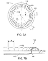
- FIGS. 7A and 7B Another alternative surround suspension element embodiment is shown in FIGS. 7A and 7B .
- the surround shown in FIGS. 7A and 7B has fewer grooves 125 and larger pitch distance P.
- Various embodiments may use arbitrary pitch distances P.
- the pitch distance P is uniform for all of the successive pairs of grooves around the circumference of the surround. In other examples, the pitch distance could vary.
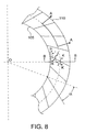
- Each groove 125 is oriented at an angle alpha as can be seen in FIG. 6A , 7A , and 8 .
- Alpha is the angle between the line of the groove and a normal to the inner edge of the surround. Alpha can vary over a wide range in different embodiments.
- the angle alpha of the groove path is preferably between 30 and 60 degrees (or -30 to -60 degrees), although useful behavior is obtained with an angle between 10 and 80 degrees (or -10 to -80 degrees).
- Negative angles of alpha refer to grooves that incline in the opposite direction from the radial (or normal) to that shown in FIG. 8 .
- Grooves 125 can be straight in plan view as in FIG 6A or curved.
- the radius of curvature along the length of the groove can be infinite (i.e. the groove is a straight line), a finite constant, or smoothly or otherwise varying.
- alpha can vary between 0 and 90 degrees, where alpha is defined in an analogous manner to the definition given below for angle of orientation of groove sections.
- a groove path may comprise a plurality of sections and a plurality of transition regions.
- the angle of orientation of each section where angle of orientation is defined as the angle of the section at the point along the section closest to the inner circumferential edge, to a normal to the inner circumferential edge that intersects the closest point, as well as the radius of curvature of the path section, can be chosen arbitrarily and independently.
- the radius of curvature of the path section can vary over the section.
- Transition regions can smoothly join the ends of adjacent path sections. For the case where the radius of curvature at the end of one section and the beginning of the section to which it is joined have opposite sign, the transition region will include an inflection point.
- the number of inflection points in a groove path is arbitrary.
- FIG. 14 One embodiment having two transition regions and three sections, with inflection points in each transition region, is shown in FIG. 14 .
- the angle of orientation of the middle section of the groove path, where the middle section traverses the middle portion of the span W between the inner and outer circumferential edges of the surround suspension element is smaller than the angles of the first and third sections.
- FIG. 9A shows a circumferential profile 140 of an exemplary surround taken along section A-A in FIG. 8 .
- Profile 140 is taken along the midpoint of the span W.
- Peaks 145 separate adjacent grooves 125 along the profile 140.
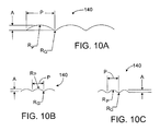
- the radius of curvature of the peak is given by R P and the radius of curvature of the groove is given by R G .
- R P 0.178
- R P 0.141
- R G 0.050
- A 0.022
- T 0.010
- R P and R G are taken to be at the local minima and local maxima of the section shown in FIG. 9A , and for convenience are measured thru the center line of the surround material (note that the radii of curvature could be defined elsewhere, such as along the top or bottom of the material surface as well).
- the value of R G given above was obtained at the point along the groove with maximum depth, and the value of R P given above was obtained at the point where the peak has maximum height.
- the profile in between the groove and peak is smooth and continuous.
- the profile have continuous curvature over its entire length.
- the profile should be free of flat areas, such as those present in the profile shown in FIG. 4 of a prior art surround.
- Continuous curvature is desirable for a circumferential section taken along the midpoint of the span W, as illustrated by profile 140 generated from section A-A in FIG. 8 . It is beneficial for the continuous curvature to be present in profiles generated from other sections taken at different radial (or normal) distances from the inner circumferential edge.
- the property of continuous curvature need not be present for profiles generated from circumferential sections taken over the entire span W, but is usefully present at least for profiles from sections taken close to the midpoint of the span W.
- R P is greater than R G .
- the profile 140 can be generally approximated by an ordinary cycloid, where Rp is unequal to Rg. In still other examples, the profile 140 is continuously curvilinear and without a constant pitch P between successive peaks.
- FIG. 9B shows a profile 150 along line B-B in FIG. 8 extending along the radial direction (or the normal to the inner circumferential edge direction) from the inner to the outer circumferential edges 105, 110 of the surround.
- Circumferential profiles of one representative groove corresponding to the section lines H-H, I-I, J-J, and K-K of FIG. 8 and 9B are shown in FIG. 9C .
- sections H-H, I-I, J-J, and K-K are all taken along the local perpendicular direction, with respect to the outer surface of the surround.
- the local groove depth is defined as the distance measured along each section, from the outer surround surface, to the bottom of the groove in that section.
- the depth of the grooves ranges from a minimum proximate to the inner circumferential edge 105, along section H-H, and progressively increases with radial distance, given by sections I-I, J-J to reach a maximum midway between the inner and outer circumferential edges, given by section K-K, then progressively decreases with increasing radial distance becoming a minimum again proximate to the outer circumferential edge.
- the bottom of the groove Following along the path of the groove from inner to outer circumferential edges, the bottom of the groove generally follows the curvature of the principal surround surface, but typically having a larger radius of curvature. Since the groove can be thought of as an inward projection of the outer surround surface, practically speaking there is no outer surround surface present directly above the bottom of the groove.
- the curvature that the bottom of the groove generally follows is that of the principal surround surface envelope. In the case of a dome shaped suspension element with grooves, the bottom of the groove would generally follow the curvature of the dome shape envelope (with larger radius of curvature).
- the radius of curvature will depend on the span W, roll height H, and the desired groove depth.
- the radius of curvature of the groove bottom path will typically be less than 3 times (for example, two times) the radius of curvature of the surround suspension element envelope. In some cases, it could be less than about 5 times (or even ten times) the radius of curvature of the surround suspension element envelope.
- the depth of the groove may vary as a function of distance along the groove path in other ways.
- the groove depth may remain constant over a large percentage of the span W of the surround (i.e. the distance between the inner and outer circumferential edges).
- the groove depth may have a plurality of local maxima and minima along the groove path, forming undulations in the bottom of the groove.
- the ratio of radius R P to radius R G , (R P / R G ) of profile 140 is less than about 10.
- FIG. 10A shows a profile 140 where R P / R G is 8.8. In other embodiments, R P / R G is less than about 5. In still other embodiments, R P / R G is less than about 3.
- FIG. 10B shows a profile 140 where R P / R G is 2.8.
- FIG. 10C shows a profile 140 where R P / R G is about 1.2. Embodiments are also possible where the ratio R P / R G is less than one.
- both radii R P , R G should be at least about three times greater than the material thickness T of the surround suspension element, where T is shown in FIG 9A . This applies for grooves and peaks present in any circumferential section that may be taken around the surround suspension element. Given a surround material thickness T of about 31 mils (0.787 mm) in one embodiment, R P , R G are greater than about 93 mils (2.36 mm). R P , R G should also generally be less then infinity (i.e. not flat), with the exception of the piecewise linear approximation mentioned earlier. In general, for practical designs R P , R G should differ from each other by no more than a factor of 20.
- the pitch P between successive peaks is at least about 4 times greater than the height A of the peaks ( FIG. 9A ).
- the height A is between about 0.025 inch (0.064 cm) and 0.10 inch (0.25 cm) and the pitch P is between about 0.15 inch (0.38 cm) and about 0.6 inch (1.52 cm).
- FIG. 11A shows graphical relationships between lateral force applied to a surround and the lateral displacement of the surround, for various surround suspension elements.
- Lateral force is any force applied to the suspension element orthogonal to the axial direction, where the axial direction is the primary direction of motion for the cone assembly.
- Curves 160 in FIG. 11A correspond to the example surround shown in FIG 7A and 7B .
- Curves 165 in FIG. 11A correspond to the prior-art surround without grooves of FIG 2A . It can be seen that the new surround of FIGS. 7A , B is substantially linear as compared with the prior art surround.
- Onset of buckling is evidenced by a deviation from a generally linear relationship in the various curves, where the onset of buckling can be seen to cause abrupt discontinuities in their lateral force/displacement curves.
- curves 165 it can be seen that there is a significant deviation from linear behavior indicating buckling in the surround, at only approximately 0.008 mm of lateral deflection (for zero axial excursion).
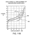
- FIGS. 11B and 11C are graphs of axial force vs. axial displacement for an exemplary surround and a prior art surround.
- FIG. 11B shows the behavior of unexercised surrounds
- FIG. 11C shows the same surrounds after 10,000 cycles of exercise at high excursion.
- the curves 170 and 175 correspond to the exemplary surround of FIG. 7A and 7B
- curves 180 and 185 correspond to the prior-art surround without grooves (as shown in FIG 2A ).
- curves 190 and 195 correspond to the exemplary surround of FIG. 7A and 7B
- curves 200 and 205 correspond to the prior-art surround without grooves (as shown in FIG 2A ).
- the graphical relationship between the axial force applied by the voice coil and the displacement of the exemplary surround is substantially linear as compared with the prior art surround.
- the onset of buckling is evidenced by a deviation from a generally linear relationship in the various curves.
- the downwardly-sagging shape of the curves for 180, 185, 200 and 205, prior to a sharp upward ascendancy at the right-hand side of the graphs shows significant non-linearity in the axial force/displacement curves of the prior art surround compared to the exemplary surround.
- the radial cross section of the suspension elements described herein have been shown using a "roll up” orientation. That is, for suspension elements with a roll shape in radial cross section, the roll extends upward, away from the cone surface. All of the embodiments herein described will also function using a “roll down” orientation. That is, the suspension element (surround or spider) can be flipped over 180 degrees, with provision made for changing mounting flanges to accommodate mounting to the cone and rigid basket.
- a “roll down” half roll conventional surround suspension element is shown in FIG. 15 .
- the surround having a configuration described herein reduces stress concentrations and reduces buckling.
- the surround and the spider are typically distinct components, separate from the cone or diaphragm, one or both may be attached to the cone using adhesives, heat staking, ultrasonic welding, or other joining processes to form an assembly.
- the surround may be formed integrally with a portion of or all of the cone. In the latter cases, the suspension structure has a virtual border even if not a discrete edge.
Landscapes
- Engineering & Computer Science (AREA)
- Physics & Mathematics (AREA)
- Acoustics & Sound (AREA)
- Signal Processing (AREA)
- Multimedia (AREA)
- Audible-Bandwidth Dynamoelectric Transducers Other Than Pickups (AREA)
- Diaphragms For Electromechanical Transducers (AREA)
Claims (39)
- Dispositif comprenant :une structure de suspension de haut-parleur (100) comportant une bordure périphérique intérieure (105) et une bordure périphérique extérieure (110) ; etdes rainures (125) qui s'étendent toutes à partir de la bordure périphérique intérieure vers la bordure périphérique extérieure en faisant un angle par rapport à une normale à la bordure périphérique intérieure ;caractérisé en ce que la structure de suspension a un profil transversal périphérique (140) qui présente une courbure continue.
- Dispositif selon la revendication 1, dans lequel les rainures (125) s'étendent seulement sur une partie de la distance entre la bordure périphérique intérieure et la bordure périphérique extérieure.
- Dispositif selon la revendication 1, dans lequel la courbure continue est cyclique.
- Dispositif selon la revendication 1, dans lequel la courbure continue comprend une succession de crêtes (145) et de rainures (125) et le rayon de courbure de chacune des crêtes est supérieur aux rayons de courbure des rainures adjacentes.
- Dispositif selon la revendication 1, dans lequel la courbure continue comprend une succession de crêtes (145) et de rainures (125) et le rayon de courbure d'au moins une partie de chacune des crêtes est inférieur aux rayons de courbure des rainures adjacentes.
- Dispositif selon la revendication 4, dans lequel le rapport entre le rayon de courbure de chacune des crêtes (145) et les rayons de courbure des rainures adjacentes (125) est inférieur à 3.
- Dispositif selon la revendication 4, dans lequel le rapport entre le rayon de courbure de chacune des crêtes (145) et les rayons de courbure des rainures adjacentes (125) est inférieur à 5.
- Dispositif selon la revendication 4, dans lequel le rapport entre le rayon de courbure de chacune des crêtes (145) et les rayons de courbure des rainures adjacentes (125) est inférieur à 10.
- Dispositif selon la revendication 4, dans lequel le rayon de courbure d'au moins une partie de chacune des crêtes (145) est supérieur aux rayons de courbure des rainures adjacentes (125).
- Dispositif selon la revendication 1, dans lequel la structure de suspension comprend une fraction de tore.
- Dispositif selon la revendication 1, dans lequel la structure de suspension présente une forme enroulée.
- Dispositif selon la revendication 1, dans lequel la forme enroulée est roulée vers le haut.
- Dispositif selon la revendication 1, dans lequel la forme enroulée est roulée vers le bas.
- Dispositif selon la revendication 1, dans lequel la forme enroulée comprend deux ou plusieurs enroulements entre la bordure périphérique intérieure (105) et la bordure périphérique extérieure (110).
- Dispositif selon la revendication 1, dans lequel le rayon de courbure de chacune des rainures (125) est au moins égal à environ trois fois l'épaisseur du matériau à partir duquel est formée la structure de suspension.
- Dispositif selon la revendication 1, dans lequel le rayon de courbure de chacune des rainures (125) est au moins égal à environ sept fois l'épaisseur du matériau à partir duquel est formée la structure de suspension.
- Dispositif selon la revendication 1, dans lequel les rainures (125) sont espacées régulièrement le long de la périphérie de la structure de suspension, chaque rainure a une certaine profondeur, et le pas d'espacement est au moins égal à environ quatre fois la profondeur.
- Dispositif selon la revendication 1, dans lequel les rainures (125) sont droites dans une vue de dessus.
- Dispositif selon la revendication 18, dans lequel l'angle des rainures (125) est dans une plage de 10 à 80 degrés.
- Dispositif selon la revendication 1, dans lequel chacune des rainures (125) comprend une courbe en vue de dessus.
- Dispositif selon la revendication 20, dans lequel l'angle des rainures (125) est dans une plage de 0 à 80 degrés.
- Dispositif selon la revendication 20, dans lequel la courbe commence en faisant un angle par rapport à la normale à la bordure périphérique intérieure (105) ou à la bordure périphérique extérieure (110).
- Dispositif selon la revendication 20, dans lequel la courbe comprend des sections.
- Dispositif selon la revendication 23, dans lequel les sections comprennent des sections droites.
- Dispositif selon la revendication 23, dans lequel les sections comprennent des sections courbes.
- Dispositif selon la revendication 23, dans lequel les sections font des angles respectifs différents par rapport à la normale à la bordure intérieure (105).
- Dispositif selon la revendication 23, dans lequel les sections comprennent aussi des sections de transition qui raccordent de façon progressive les sections droites ou courbes.
- Dispositif selon la revendication 23, dans lequel les sections se rejoignent à des points d'inflexion.
- Dispositif selon la revendication 1, dans lequel chacune des rainures (125) a une profondeur qui varie depuis la bordure intérieure (105) jusqu'à la bordure extérieure (110).
- Dispositif selon la revendication 29, dans lequel la variation correspond à la variation de hauteur d'un profil principal de la structure de suspension.
- Dispositif selon la revendication 29, dans lequel les rainures (125) ont un rayon de courbure plus grand que celui du profil principal.
- Dispositif selon la revendication 1, dans lequel chacune des rainures (125) a une profondeur généralement constante le long de la plus grande partie du trajet de la rainure.
- Dispositif selon la revendication 29, dans lequel la rainure (125) comprend deux ou plusieurs minimums ou maximums locaux.
- Dispositif selon la revendication 1, dans lequel une section transversale radiale de la structure de suspension (100) a la forme d'un tore partiel.
- Dispositif selon la revendication 1, dans lequel une section transversale radiale de la structure de suspension (100) a une forme différente d'un tore partiel.
- Dispositif selon la revendication 1, dans lequel une section transversale radiale de la structure de suspension (100) comporte deux ou plusieurs minimums ou maximums locaux.
- Dispositif selon la revendication 1, dans lequel la courbure continue comprend un profil linéaire par morceaux.
- Dispositif selon la revendication 1, dans lequel la structure de suspension (100) constitue une suspension périphérique.
- Dispositif selon la revendication 1, dans lequel la structure de suspension (100) constitue un anneau de centrage (spider).
Applications Claiming Priority (1)
| Application Number | Priority Date | Filing Date | Title |
|---|---|---|---|
| US10/993,996 US7397927B2 (en) | 2004-11-19 | 2004-11-19 | Loudspeaker suspension |
Publications (3)
| Publication Number | Publication Date |
|---|---|
| EP1659823A2 EP1659823A2 (fr) | 2006-05-24 |
| EP1659823A3 EP1659823A3 (fr) | 2006-08-02 |
| EP1659823B1 true EP1659823B1 (fr) | 2008-07-30 |
Family
ID=35708956
Family Applications (1)
| Application Number | Title | Priority Date | Filing Date |
|---|---|---|---|
| EP05110837A Expired - Lifetime EP1659823B1 (fr) | 2004-11-19 | 2005-11-16 | Suspension pour haut-parleur |
Country Status (5)
| Country | Link |
|---|---|
| US (1) | US7397927B2 (fr) |
| EP (1) | EP1659823B1 (fr) |
| JP (1) | JP5020503B2 (fr) |
| CN (1) | CN1794882A (fr) |
| DE (1) | DE602005008539D1 (fr) |
Families Citing this family (25)
| Publication number | Priority date | Publication date | Assignee | Title |
|---|---|---|---|---|
| US8139812B2 (en) * | 2004-11-19 | 2012-03-20 | Subarna Basnet | Loudspeaker suspension |
| US7931115B2 (en) * | 2007-05-31 | 2011-04-26 | Bose Corporation | Diaphragm surrounding |
| US7699139B2 (en) * | 2007-05-31 | 2010-04-20 | Bose Corporation | Diaphragm surround |
| BRPI0917410A2 (pt) | 2008-08-14 | 2015-12-01 | Harman Int Ind | tampão de fase e lente acústica para alto-falante de radiação direta |
| WO2010090201A1 (fr) * | 2009-02-09 | 2010-08-12 | 三洋電機株式会社 | Unité de haut-parleur et terminal d'informations portable |
| US8290199B2 (en) | 2009-05-21 | 2012-10-16 | Bose Corporation | Loudspeaker suspension |
| US8340340B2 (en) * | 2010-01-07 | 2012-12-25 | Paradigm Electronics Inc. | Loudspeaker driver suspension |
| USD654479S1 (en) | 2010-01-07 | 2012-02-21 | Paradigm Electronics Inc. | Loudspeaker driver suspension |
| US8397861B1 (en) | 2012-03-02 | 2013-03-19 | Bose Corporation | Diaphragm surround |
| DE112012006347T5 (de) | 2012-05-08 | 2015-01-29 | Harman International (China) Holdings Co., Ltd. | Neuer Lautsprecher |
| JP2014127883A (ja) * | 2012-12-27 | 2014-07-07 | Namiki Precision Jewel Co Ltd | 多機能型振動アクチュエータのサスペンション構造 |
| US9253576B2 (en) * | 2013-11-21 | 2016-02-02 | Bose Corporation | Suspension for acoustic device |
| CN109905816B (zh) * | 2014-01-22 | 2021-01-26 | 宁波升亚电子有限公司 | 一种无弹波扬声器及其制造方法 |
| US9277303B2 (en) | 2014-01-22 | 2016-03-01 | Bose Corporation | Treatment for loudspeaker suspension element fabric |
| US9148727B1 (en) | 2014-03-19 | 2015-09-29 | Bose Corporation | Non-axisymmetric geometry for cloth loudspeaker suspensions |
| TWI483626B (zh) * | 2014-03-19 | 2015-05-01 | Merry Electronics Co Ltd | 具懸邊改良結構之振膜 |
| CN105872916B (zh) * | 2015-01-22 | 2023-04-21 | 宁波升亚电子有限公司 | 弹肋式悬边和扬声器及其制造方法 |
| GB2560496B (en) * | 2017-03-16 | 2021-09-29 | Gp Acoustics Uk Ltd | Loudspeaker driver surround |
| CN110754094B (zh) * | 2017-07-27 | 2021-06-22 | 索尼公司 | 振动板的边缘和扬声器单元 |
| US10708694B2 (en) * | 2017-09-11 | 2020-07-07 | Apple Inc. | Continuous surround |
| CN109788408B (zh) * | 2017-11-10 | 2023-08-22 | 惠州迪芬尼声学科技股份有限公司 | 扬声器的悬边结构 |
| CN208638609U (zh) * | 2018-06-12 | 2019-03-22 | 瑞声科技(新加坡)有限公司 | 振膜及具有该振膜的发声器 |
| USD916053S1 (en) * | 2018-11-09 | 2021-04-13 | Purifi Aps | Part of a loudspeaker |
| EP3723387A1 (fr) | 2019-04-11 | 2020-10-14 | Purifi ApS | Haut-parleur avec une suspension non uniforme et un élément d'application |
| DE112021006336T5 (de) * | 2020-12-07 | 2023-10-19 | Sony Group Corporation | Rand, lautsprechereinheit, mikrofon und akustische verarbeitungsvorrichtung |
Citations (3)
| Publication number | Priority date | Publication date | Assignee | Title |
|---|---|---|---|---|
| JPS6027299A (ja) * | 1983-07-25 | 1985-02-12 | Matsushita Electric Ind Co Ltd | スピ−カ用振動板 |
| JPS61276499A (ja) * | 1985-05-31 | 1986-12-06 | Pioneer Electronic Corp | スピ−カ用振動板 |
| US20030231784A1 (en) * | 2002-05-17 | 2003-12-18 | Mitsukazu Kuze | Surrounding structure of a loudspeaker |
Family Cites Families (30)
| Publication number | Priority date | Publication date | Assignee | Title |
|---|---|---|---|---|
| US1734624A (en) | 1926-04-16 | 1929-11-05 | Bell Telephone Labor Inc | Piston diaphragm having tangential corrugations |
| US1891566A (en) | 1932-01-07 | 1932-12-20 | Philadelphia Storage Battery | Flexible hinge ring |
| US2302178A (en) | 1940-11-12 | 1942-11-17 | Joseph B Brennan | Acoustic diaphragm |
| US2439665A (en) | 1944-01-31 | 1948-04-13 | Rca Corp | Sound reproducing device |
| GB726780A (en) | 1952-01-19 | 1955-03-23 | Cole E K Ltd | Improvements in or relating to sound producing diaphragms |
| US3563337A (en) | 1968-03-06 | 1971-02-16 | Hitachi Ltd | Electroacoustic transducer |
| US3983337A (en) | 1973-06-21 | 1976-09-28 | Babbco, Ltd. | Broad-band acoustic speaker |
| JPS5135128U (fr) * | 1974-09-09 | 1976-03-16 | ||
| US3997023A (en) | 1975-12-10 | 1976-12-14 | White Stanley F | Loudspeaker with improved surround |
| JPS5434589Y2 (fr) * | 1978-02-23 | 1979-10-23 | ||
| US4324312A (en) | 1978-11-14 | 1982-04-13 | James B. Lansing Sound, Inc. | Diaphragm suspension construction |
| JPS55121593U (fr) * | 1979-02-20 | 1980-08-28 | ||
| JPS5613897A (en) * | 1979-07-13 | 1981-02-10 | Toshiba Corp | Supporting device for ring-shaped diaphragm |
| JPH0317520Y2 (fr) * | 1981-06-24 | 1991-04-12 | ||
| US4433214A (en) * | 1981-12-24 | 1984-02-21 | Motorola, Inc. | Acoustical transducer with a slotted piston suspension |
| JPS58127499A (ja) | 1982-01-25 | 1983-07-29 | Matsushita Electric Ind Co Ltd | スピ−カの振動系支持装置 |
| JPS5950698A (ja) | 1982-09-17 | 1984-03-23 | Toshiba Corp | スピ−カ用センタ−サスペンシヨン |
| JPS59111389U (ja) * | 1983-01-17 | 1984-07-27 | パイオニア株式会社 | 音響再生用振動板 |
| JPS6126499A (ja) | 1984-07-17 | 1986-02-05 | Mitsubishi Electric Corp | ステツピツグ・モ−タ駆動装置 |
| US4881617A (en) | 1988-12-30 | 1989-11-21 | Alexander Faraone | Radially arcuated speaker cone |
| DE69332093T2 (de) * | 1992-02-21 | 2003-03-13 | Matsushita Electric Industrial Co., Ltd. | Lautsprecher |
| US5903656A (en) * | 1996-05-31 | 1999-05-11 | Philips Electronics North America Corporation | Monitor has tubular loudspeaker reducing CRT's mask vibrations |
| EP0963136B1 (fr) * | 1998-05-08 | 2011-08-31 | Panasonic Corporation | Haut-parleur |
| US6449375B1 (en) * | 1999-09-22 | 2002-09-10 | Harmon International Industries, Incorporated | Loudspeaker spider with regressive rolls |
| US6567528B1 (en) * | 1999-11-18 | 2003-05-20 | Harman International Industries, Incorporated | Offset apex spider |
| GB2374753B (en) | 2001-01-29 | 2004-12-22 | Goodmans Loudspeakers Ltd | Loudspeaker suspension |
| US6851513B2 (en) | 2001-03-27 | 2005-02-08 | Harvard International Industries, Incorporated | Tangential stress reduction system in a loudspeaker suspension |
| EP1413170A2 (fr) * | 2001-07-19 | 2004-04-28 | Koninklijke Philips Electronics N.V. | Transducteur electroacoustique comprenant une membrane a zone de plis amelioree |
| CA2407123C (fr) | 2001-10-16 | 2007-12-18 | Audio Products International Corp. | Suspension de cone de haut-parleur a faible distorsion |
| JP2004048494A (ja) | 2002-07-12 | 2004-02-12 | Pioneer Electronic Corp | スピーカ装置及びスピーカ用振動板 |
-
2004
- 2004-11-19 US US10/993,996 patent/US7397927B2/en not_active Expired - Lifetime
-
2005
- 2005-11-16 DE DE602005008539T patent/DE602005008539D1/de not_active Expired - Lifetime
- 2005-11-16 EP EP05110837A patent/EP1659823B1/fr not_active Expired - Lifetime
- 2005-11-18 JP JP2005334946A patent/JP5020503B2/ja not_active Expired - Fee Related
- 2005-11-21 CN CNA2005101267218A patent/CN1794882A/zh active Pending
Patent Citations (3)
| Publication number | Priority date | Publication date | Assignee | Title |
|---|---|---|---|---|
| JPS6027299A (ja) * | 1983-07-25 | 1985-02-12 | Matsushita Electric Ind Co Ltd | スピ−カ用振動板 |
| JPS61276499A (ja) * | 1985-05-31 | 1986-12-06 | Pioneer Electronic Corp | スピ−カ用振動板 |
| US20030231784A1 (en) * | 2002-05-17 | 2003-12-18 | Mitsukazu Kuze | Surrounding structure of a loudspeaker |
Also Published As
| Publication number | Publication date |
|---|---|
| EP1659823A3 (fr) | 2006-08-02 |
| US7397927B2 (en) | 2008-07-08 |
| CN1794882A (zh) | 2006-06-28 |
| JP5020503B2 (ja) | 2012-09-05 |
| DE602005008539D1 (de) | 2008-09-11 |
| JP2006148923A (ja) | 2006-06-08 |
| EP1659823A2 (fr) | 2006-05-24 |
| US20060110002A1 (en) | 2006-05-25 |
Similar Documents
| Publication | Publication Date | Title |
|---|---|---|
| EP1659823B1 (fr) | Suspension pour haut-parleur | |
| US8139812B2 (en) | Loudspeaker suspension | |
| US9253576B2 (en) | Suspension for acoustic device | |
| CN101002502B (zh) | 用于具有可动线圈的扬声器的振膜 | |
| US10129652B2 (en) | Audio speaker surround geometry for improved pistonic motion | |
| US8340340B2 (en) | Loudspeaker driver suspension | |
| EP2952014B1 (fr) | Diaphragme électroacoustique | |
| US10142736B2 (en) | Electroacoustic transducer | |
| CN108632722B (zh) | 扬声器驱动器环绕件 | |
| JP4834004B2 (ja) | 動的コンバータのための膜 | |
| US6134337A (en) | Loudspeaker | |
| JP3633796B2 (ja) | スリムスピーカ | |
| KR101073646B1 (ko) | 스피커의 진동계 지지기구 | |
| HK1092638A (en) | Loudspeaker suspension | |
| JP2000041295A (ja) | スピーカ用振動板 | |
| CN116801170A (zh) | 一种振动组件及扬声器 | |
| JPS5950698A (ja) | スピ−カ用センタ−サスペンシヨン | |
| JPS60199297A (ja) | スピ−カ用振動板 | |
| HK1254523A1 (en) | Loudspeaker driver surround | |
| HK1218209B (zh) | 电声学隔膜 |
Legal Events
| Date | Code | Title | Description |
|---|---|---|---|
| PUAI | Public reference made under article 153(3) epc to a published international application that has entered the european phase |
Free format text: ORIGINAL CODE: 0009012 |
|
| AK | Designated contracting states |
Kind code of ref document: A2 Designated state(s): AT BE BG CH CY CZ DE DK EE ES FI FR GB GR HU IE IS IT LI LT LU LV MC NL PL PT RO SE SI SK TR |
|
| AX | Request for extension of the european patent |
Extension state: AL BA HR MK YU |
|
| PUAL | Search report despatched |
Free format text: ORIGINAL CODE: 0009013 |
|
| AK | Designated contracting states |
Kind code of ref document: A3 Designated state(s): AT BE BG CH CY CZ DE DK EE ES FI FR GB GR HU IE IS IT LI LT LU LV MC NL PL PT RO SE SI SK TR |
|
| AX | Request for extension of the european patent |
Extension state: AL BA HR MK YU |
|
| 17P | Request for examination filed |
Effective date: 20070129 |
|
| 17Q | First examination report despatched |
Effective date: 20070301 |
|
| AKX | Designation fees paid |
Designated state(s): DE GB |
|
| GRAP | Despatch of communication of intention to grant a patent |
Free format text: ORIGINAL CODE: EPIDOSNIGR1 |
|
| GRAS | Grant fee paid |
Free format text: ORIGINAL CODE: EPIDOSNIGR3 |
|
| GRAA | (expected) grant |
Free format text: ORIGINAL CODE: 0009210 |
|
| AK | Designated contracting states |
Kind code of ref document: B1 Designated state(s): DE GB |
|
| REG | Reference to a national code |
Ref country code: GB Ref legal event code: FG4D |
|
| REF | Corresponds to: |
Ref document number: 602005008539 Country of ref document: DE Date of ref document: 20080911 Kind code of ref document: P |
|
| PLBE | No opposition filed within time limit |
Free format text: ORIGINAL CODE: 0009261 |
|
| STAA | Information on the status of an ep patent application or granted ep patent |
Free format text: STATUS: NO OPPOSITION FILED WITHIN TIME LIMIT |
|
| 26N | No opposition filed |
Effective date: 20090506 |
|
| PGFP | Annual fee paid to national office [announced via postgrant information from national office to epo] |
Ref country code: GB Payment date: 20201127 Year of fee payment: 16 |
|
| GBPC | Gb: european patent ceased through non-payment of renewal fee |
Effective date: 20211116 |
|
| PG25 | Lapsed in a contracting state [announced via postgrant information from national office to epo] |
Ref country code: GB Free format text: LAPSE BECAUSE OF NON-PAYMENT OF DUE FEES Effective date: 20211116 |
|
| PGFP | Annual fee paid to national office [announced via postgrant information from national office to epo] |
Ref country code: DE Payment date: 20241022 Year of fee payment: 20 |
|
| REG | Reference to a national code |
Ref country code: DE Ref legal event code: R071 Ref document number: 602005008539 Country of ref document: DE |