EP1659908B1 - Systeme de chauffage de plateaux de rations ameliore - Google Patents
Systeme de chauffage de plateaux de rations ameliore Download PDFInfo
- Publication number
- EP1659908B1 EP1659908B1 EP04779099A EP04779099A EP1659908B1 EP 1659908 B1 EP1659908 B1 EP 1659908B1 EP 04779099 A EP04779099 A EP 04779099A EP 04779099 A EP04779099 A EP 04779099A EP 1659908 B1 EP1659908 B1 EP 1659908B1
- Authority
- EP
- European Patent Office
- Prior art keywords
- reservoir
- along
- firebox
- heat exchanger
- opening
- Prior art date
- Legal status (The legal status is an assumption and is not a legal conclusion. Google has not performed a legal analysis and makes no representation as to the accuracy of the status listed.)
- Expired - Lifetime
Links
- 238000010438 heat treatment Methods 0.000 title claims abstract description 39
- 239000007789 gas Substances 0.000 claims description 68
- 239000007788 liquid Substances 0.000 claims description 12
- 238000009413 insulation Methods 0.000 claims description 3
- XLYOFNOQVPJJNP-UHFFFAOYSA-N water Substances O XLYOFNOQVPJJNP-UHFFFAOYSA-N 0.000 description 12
- 238000002485 combustion reaction Methods 0.000 description 8
- 238000003466 welding Methods 0.000 description 7
- 239000000463 material Substances 0.000 description 6
- 235000013305 food Nutrition 0.000 description 5
- 239000010935 stainless steel Substances 0.000 description 4
- 229910001220 stainless steel Inorganic materials 0.000 description 4
- 238000005260 corrosion Methods 0.000 description 3
- 230000007797 corrosion Effects 0.000 description 3
- 238000012986 modification Methods 0.000 description 3
- 230000004048 modification Effects 0.000 description 3
- VYPSYNLAJGMNEJ-UHFFFAOYSA-N Silicium dioxide Chemical compound O=[Si]=O VYPSYNLAJGMNEJ-UHFFFAOYSA-N 0.000 description 2
- 230000000712 assembly Effects 0.000 description 2
- 238000000429 assembly Methods 0.000 description 2
- 238000005452 bending Methods 0.000 description 2
- 239000000567 combustion gas Substances 0.000 description 2
- 229910000856 hastalloy Inorganic materials 0.000 description 2
- 238000000034 method Methods 0.000 description 2
- 239000000203 mixture Substances 0.000 description 2
- 230000002093 peripheral effect Effects 0.000 description 2
- 229910045601 alloy Inorganic materials 0.000 description 1
- 239000000956 alloy Substances 0.000 description 1
- PNEYBMLMFCGWSK-UHFFFAOYSA-N aluminium oxide Inorganic materials [O-2].[O-2].[O-2].[Al+3].[Al+3] PNEYBMLMFCGWSK-UHFFFAOYSA-N 0.000 description 1
- 239000002131 composite material Substances 0.000 description 1
- 238000010411 cooking Methods 0.000 description 1
- 230000001351 cycling effect Effects 0.000 description 1
- -1 e.g. Substances 0.000 description 1
- 239000000446 fuel Substances 0.000 description 1
- 239000003779 heat-resistant material Substances 0.000 description 1
- 239000008236 heating water Substances 0.000 description 1
- 238000003780 insertion Methods 0.000 description 1
- 230000037431 insertion Effects 0.000 description 1
- 239000011810 insulating material Substances 0.000 description 1
- 239000012774 insulation material Substances 0.000 description 1
- 238000004519 manufacturing process Methods 0.000 description 1
- 239000002184 metal Substances 0.000 description 1
- 238000002360 preparation method Methods 0.000 description 1
- 238000007789 sealing Methods 0.000 description 1
- 239000003566 sealing material Substances 0.000 description 1
- 239000000377 silicon dioxide Substances 0.000 description 1
- 229920002379 silicone rubber Polymers 0.000 description 1
- 235000014347 soups Nutrition 0.000 description 1
- 235000013547 stew Nutrition 0.000 description 1
- 238000003860 storage Methods 0.000 description 1
- 230000007704 transition Effects 0.000 description 1
- 239000011800 void material Substances 0.000 description 1
Images



Classifications
-
- A—HUMAN NECESSITIES
- A47—FURNITURE; DOMESTIC ARTICLES OR APPLIANCES; COFFEE MILLS; SPICE MILLS; SUCTION CLEANERS IN GENERAL
- A47J—KITCHEN EQUIPMENT; COFFEE MILLS; SPICE MILLS; APPARATUS FOR MAKING BEVERAGES
- A47J27/00—Cooking-vessels
- A47J27/14—Cooking-vessels for use in hotels, restaurants, or canteens
- A47J27/18—Cooking-vessels for use in hotels, restaurants, or canteens heated by water-bath, e.g. pasta-cookers
-
- A—HUMAN NECESSITIES
- A47—FURNITURE; DOMESTIC ARTICLES OR APPLIANCES; COFFEE MILLS; SPICE MILLS; SUCTION CLEANERS IN GENERAL
- A47J—KITCHEN EQUIPMENT; COFFEE MILLS; SPICE MILLS; APPARATUS FOR MAKING BEVERAGES
- A47J36/00—Parts, details or accessories of cooking-vessels
- A47J36/24—Warming devices
- A47J36/26—Devices for warming vessels containing drinks or food, especially by means of burners Warming devices with a burner, e.g. using gasoline; Travelling cookers, e.g. using petroleum or gasoline with one burner
-
- A—HUMAN NECESSITIES
- A47—FURNITURE; DOMESTIC ARTICLES OR APPLIANCES; COFFEE MILLS; SPICE MILLS; SUCTION CLEANERS IN GENERAL
- A47J—KITCHEN EQUIPMENT; COFFEE MILLS; SPICE MILLS; APPARATUS FOR MAKING BEVERAGES
- A47J37/00—Baking; Roasting; Grilling; Frying
- A47J37/12—Deep fat fryers, e.g. for frying fish or chips
- A47J37/1242—Deep fat fryers, e.g. for frying fish or chips heated with burners
- A47J37/1247—Details of the burners; Details of the channels for guiding the combustion gases
-
- A—HUMAN NECESSITIES
- A47—FURNITURE; DOMESTIC ARTICLES OR APPLIANCES; COFFEE MILLS; SPICE MILLS; SUCTION CLEANERS IN GENERAL
- A47J—KITCHEN EQUIPMENT; COFFEE MILLS; SPICE MILLS; APPARATUS FOR MAKING BEVERAGES
- A47J39/00—Heat-insulated warming chambers; Cupboards with heating arrangements for warming kitchen utensils
- A47J39/006—Heat-insulated warming chambers; Cupboards with heating arrangements for warming kitchen utensils for either storing and preparing or for preparing food on serving trays, e.g. heating, thawing, preserving
-
- F—MECHANICAL ENGINEERING; LIGHTING; HEATING; WEAPONS; BLASTING
- F23—COMBUSTION APPARATUS; COMBUSTION PROCESSES
- F23M—CASINGS, LININGS, WALLS OR DOORS SPECIALLY ADAPTED FOR COMBUSTION CHAMBERS, e.g. FIREBRIDGES; DEVICES FOR DEFLECTING AIR, FLAMES OR COMBUSTION PRODUCTS IN COMBUSTION CHAMBERS; SAFETY ARRANGEMENTS SPECIALLY ADAPTED FOR COMBUSTION APPARATUS; DETAILS OF COMBUSTION CHAMBERS, NOT OTHERWISE PROVIDED FOR
- F23M9/00—Baffles or deflectors for air or combustion products; Flame shields
- F23M9/003—Baffles or deflectors for air or combustion products; Flame shields in flue gas ducts
Definitions
- This disclosure relates to a system for heating water or other liquids, and more particularly relates to a portable system for heating relatively large volumes of liquid, and even more particularly relates to a portable system for cooking food which offers improved heat transfer to the liquid volume and improved safety for the operators of the system.
- the disclosed tray ration heating system includes a thirty gallon tub heated by a liquid fuel burner.
- the device is supported on a pair of skids, and requires only two personnel to load it in a vehicle where it may be rapidly transported to the area of food preparation.
- the lid is closed. Heat is supplied along the sides and underside of the tub raising the temperature of the water bath containing the tray rations containers to a temperature of approximately 200°F. Once the bath has reached temperature, a temperature sensor turns the burner off, and cycling of the burning occurs to maintain the selected temperature.
- GB 389,182 relates to improvements in or relating to stoves for frying, water heating and other purposes.
- a combination of a heating chamber and outlet flue leading from said camber and a frying pan, water heater or other article to be heated is disclosed, adapted to co-operate with the heating chamber to form a closed space.
- the bottom of said article is being provided with ribs which are integral herewith and form, together with the bottom of said article and the heating chamber, passages which direct the products of combustion towards the outlet flue.
- US 4,848,318 is related to a high efficiency frying apparatus with supercharged burner system.
- Burner assemblies are disposed on each side of a center section and form combustion chambers for the combustion of a fuel-air mixture introduced into combustion chambers under a forced air flow system.
- the combustion chambers are charged with a forced flow of a fuel-air mixture under positive pressure by a blower assembly mounted on a manifold on the front of the frypot assembly.
- the manifold includes respective air flow control valve gates which may be selectively adjusted to balance the charging air flow to the respective burner assemblies.
- the frypot has opposed sidewalls and a rear wall which form parts of respective flow passages for combustion gases leaving the combustion chambers.
- the foregoing system of the prior art utilizes a type of heat exchange system which while effective, is not efficient or user friendly was it could be. Accordingly, the foregoing heat exchange system has been redesigned in accordance with the present invention.
- An improved tray ration heating system includes a reservoir for heating tray rations in a bath of water.
- a firebox under the bottom of the reservoir is opened at the top facing the reservoir.
- the heat exchanger extends from the firebox along the bottom of the reservoir and along one vertical side of the reservoir.
- the heat exchanger forms a plurality of channels with the bottom of the reservoir for directing heat in first and second opposite direction.
- a passageway is formed along the vertical side for directing heat from the plurality of channels to an exhaust opening.
- An outer liner encloses the reservoir beat exchanger and firebox and supports a lid for closing the reservoir during heating of tray rations.
- a burner and controller supply heat to the firebox which is transferred through the channels and passageway, heating the bottom and vertical side of the reservoir to a temperature for heating the bath of water containing tray rations.
- a tray ration heating system includes a reservoir open at its top to receive tray rations and immerse tray rations in hot water.
- a heat exchanger transfers heat to the reservoir.
- the heat exchanger includes a firebox at one end of the reservoir.
- the firebox has an opening at one end to receive a burner flame tube and is open along a top which faces an underside of the reservoir.
- the firebox has an opening at an opposite end to deliver products of combustion, hereinafter referred to as hot gases or exhaust gases, from the burner along the underside of the reservoir to an opposite end of the reservoir.
- a main channel of the heat exchanger communicates with the opening and extends the length of the reservoir underside.
- the channel includes a first plurality of baffles for introducing turbulence to hot gases moving through the channel towards the opposite end of the reservoir as well as increase the effective path length of the heat exchanger.
- First and second auxiliary channels adjacent to the main channel are arranged to direct hot gases exiting the main channel along the underside of the reservoir back towards the firebox.
- Third and fourth auxiliary channels adjacent to the first and second auxiliary channels direct hot gases exiting the first and second channels towards the opposite end of the reservoir.
- An exhaust channel communicates with the third and fourth auxiliary channels and extends along a vertical wall of the reservoir for directing the hot gases along the vertical wall to an exhaust opening.
- the exhaust channel has a second plurality of baffles for laterally displacing the hot gases across the vertical wall thereby increasing the effective length of the heat exchanger.
- An insulated outer liner supports the reservoir and heat exchanger.
- the insulated outer liner has a lid which closes the reservoir top during heating.
- the outer liner also supports the burner which has a flame tube which extends into the firebox.
- a pair of skids is connected to the outer liner to provide support for the tray ration heating system on the ground or other suitable surface.
- a heat exchanger system suitable for use in transferring heat to a reservoir of liquid includes a burner with a flame tube inserted into a firebox having an opening at one end which receives the flame tube, and a tapered (angled) opening at an opposite end through which exhaust gases produced by the burner flows.
- a main channel communicates with the tapered opening and extends in a first direction from an end of the reservoir along a surface of the reservoir to an opposite end of the reservoir. The main channel guides the heated combustion gases along the first direction.
- First baffle means arranged in the main channel provides directed flow of exhaust gases in a turbulence flow as the heated gases travel through the main channel towards the opposite end of the reservoir in the first direction.
- First and second auxiliary channels lie adjacent to the main channel and are joined together at an open end portion of the main channel.
- the first and second auxiliary channels are separated by the main channel and arranged to direct the heated gases in a second direction along the surface of the reservoir opposite to the first direction.
- the first and second auxiliary channels direct the heated gases exiting the main channel from the opposite end of the reservoir back towards the firebox.
- Third and fourth auxiliary channels are arranged to direct the heated gases exiting the first and second channels towards the opposite end of the reservoir along the surface of the reservoir in the first direction.
- a vertical exhaust channel communicates with the third and fourth auxiliary channels and extends along a vertical wall of the reservoir.
- the vertical exhaust channel is arranged to direct the heated gases along the vertical wall to an exhaust opening.
- Second baffle means are arranged in the vertical exhaust channel to laterally displace the heated gases across an end portion width of the reservoir before the heated gases reach the exhaust opening.
- An insulated outer cover contains or envelopes the reservoir and heat exchanger.
- the insulated outer liner has a lid which closes to cover the reservoir top during heating.
- the insulated outer cover both supports the burner and insulates the burner from an external environment.
- a method for transferring heat to a reservoir of liquid through a heat exchanger includes introducing heated gases into a firebox; flowing the heated gases from the firebox along a surface of the reservoir in a first direction; reversing the direction of the heated gas flow along the surface of the reservoir in a second direction; again reversing the heated gas flow along the surface of the reservoir to direct the heated gas flow in the first direction; directing the heated gas flow along a vertical surface of the reservoir; laterally displacing the heated gas flow along the vertical surface of the reservoir; and exhausting the heated gas flow from the heat exchanger.
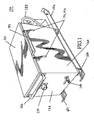
- FIG. 1 is a perspective view of an improved tray ration heating system according to an exemplary embodiment of the invention
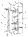
- FIG. 2 is a perspective view of the improved tray ration heating system of FIG. 1 with its top open, showing a portion of the inside of the system, including racks for receiving tray rations;
- FIG. 3 is a perspective view of an embodiment of the invention illustrating the exterior of the firebox and heat exchanger attached to the underside of a reservoir;
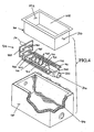
- FIG. 4 provides an exploded perspective view illustrating the relative arrangement of the reservoir, firebox : and heat exchanger, and insulated outer cover of the embodiment of FIG. 1 ;
- FIG. 5 provides a cross-sectional view of the heat exchanger in elevation looking from an end of the arrangement shown in FIG. 1 ;
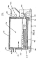
- FIG. 6 provides a cross-sectional view in elevation looking from a side of the arrangement shown in FIG. 1 ;
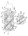
- FIG. 7 provides a plan view of a main portion of the heat exchanger and firebox of an embodiment of the invention illustrating the flow of heated gases from the firebox through the heat exchanger;
- FIG. 8 provides an elevation view of the vertical portion of the heat exchanger and exhaust port of an embodiment of the invention, which also illustrates the flow of heated gases from the main portion of the heat exchanger of FIG. 7 , through the vertical portion of the heat exchanger, to the exhaust port;
- FIG. 9 illustrates thermocouple placement and representative temperatures internal to the heat exchanger.
- an exterior, closed view of an embodiment of tray ration heating system 100 includes top 110 connected to insulated outer liner 120 by one or more hinges (not shown).
- Top 110 may include a suitable gasket material (not shown) for effective sealing to prevent liquid leakage.
- Exhaust pipe 130 and water drain valve 140 protrude through insulated outer liner 120.
- Support skids 151 and 152 are attached to insulated outer liner 120 by resilient mounts 160.
- Latches 171 and 172 releasably hold top 110 in a closed position with respect to insulated outer liner 120.
- Handle 181 is connected to top 110 for ease of opening and closing.
- Handle 182 is attached to the exhaust end of insulated outer liner 120.
- Handles 183 and 184 are attached to the burner end of insulated outer liner 120.
- Tray ration heating system 100 is portable, and rugged, and may be used in a variety of relatively harsh operating environments in the field, including heat on the move applications.
- tray ration heating system 100 is shown with top 110 held open with locking support arm 220.
- Rack assembly 230 is arranged within reservoir or inner tub 240 to receive tray rations or tray packs 250 (shown in dashed lines), and immerse them in hot water, for example, contained by reservoir 240.
- Reservoir 240 may generally be any size necessary to meet the particular operational requirements, but may be sized, for example, to have a 30-gallon capacity.
- Controller 260 and burner assembly 270 are arranged at the burner end of tray ration heating system 100.
- Controller 260 may be powered by standard 120 VAC, or other suitably converted AC or DC supply voltage.
- Controller 260 may include an "on/off' switch (not shown), and other control actuators and safety elements.
- Burner assembly 270 may be a Babington Enterprises Airtronic ® Burner.
- Top 110 and reservoir 240 may be constructed from stainless steel, for example, SS 304, or other corrosion resistant metal, and possibly could be made from other corrosion and heat resistant materials, such as composite materials, as necessary or desired to meet particular operational or functional requirements.
- FIG. 3 shows an underside of reservoir 240, with insulated outer liner 120 removed for clarity.
- outer shell 310 of heat exchanger 400 maybe arranged on a bottom of reservoir 240 and along a back vertical wall to transfer heat to reservoir 240 and its contents, e.g., water.
- firebox 320 is arranged at the burner end of reservoir 240.
- Firebox 320 includes conical flame tube 330 having opening 340 which facilitates insertion of a burner flame tube (not shown) of burner assembly 270.
- Outer shell 310 may be notched at one end to fit around at least a portion of firebox 320, and also covers the internal components and structure of heat exchanger 400, as discussed below.
- Low-water level sensor 350 may be arranged on a side or end of reservoir 240 and may be operatively coupled to controller 260 for safety shut off, in the event that the liquid level in reservoir 240 becomes too low during operation.
- Water drain valve 360 is arranged at a relatively low position on a side or end of reservoir 240 to facilitate draining reservoir 240.
- Reservoir 240 may also have a temperature sensor (not shown) coupled to controller 260 to control the burner on-off sequence to establish a desired temperature of the liquid in reservoir 240, and to prevent an unsafe temperature situation from arising.
- FIG. 4 depicts, in an expanded view, the relative arrangement of the component parts during assembly of system 100.
- exemplary aspects of heat exchanger 400 are able to be viewed, as well as further details of insulated outer liner 120.
- FIG. 7 provides a plan view of heat exchanger 400, with flow paths of various channels formed with the bottom of reservoir 240.
- heat exchanger 400 includes primary channel assembly 410 which is attached to firebox 320.
- Primary channel assembly 410 may be Hastalloy X ® high temperature alloy, or other high temperature, corrosion resistant material. Tapered portion or angled opening 415 is internal to firebox 320, and provides a relatively smooth transition piece which acts to more efficiently deliver hot gases from the burner flame tube inserted into firebox 320 in heat exchanger 400, and reduce the amount of heat reflection back to the burner.
- the hot gases flow from firebox 320 through channel assembly 410 along the underside of reservoir 240 to an opposite end of reservoir 240.
- An outer shell of firebox 320 may be made from stainless steel, e.g., SS 304, and an interior portion of firebox 320, including tapered or angled portion 415, may be lined with commercially available hardboard insulation, e.g., alumina silica, or other insulation material suitable for withstanding temperatures in firebox 320 in excess of 2200°F.
- Main channel baffles 420 are arranged along a surface of primary channel assembly 410. A portion of main channel baffles 420 are in a central region of a lateral surface of primary channel assembly 410, and some are arranged at a peripheral region of primary channel assembly 410, abutting with perimeter walls 425 and 426, for example. Main channel baffles 420 act to create turbulence in the flow of hot gases provided from firebox 320, and to encourage more lateral flow of hot gases along primary channel assembly 410 from the burner end of reservoir 240 to the other end of reservoir 240.
- Main channel baffles 420 may also be made from Hastalloy X ® , and may have an "L"-shaped cross-section (not shown) formed from bending plate material to about a 90° angle. The shorter length portion of the "L"-shape may be spot or tack welded, for example, or otherwise suitably attached to the lateral surface portion of primary channel assembly 410 to provide the necessary structural support.
- Primary channel assembly 410 has perimeter walls 425 and 426 arranged essentially parallel to each other except for an angled portion at an open end portion of primary channel assembly 410.
- Perimeter walls 425 and 426 are connected to and extend from firebox 320, as shown in FIGS. 4 and 7 .
- Perimeter walls 425 may be integrally attached to the lateral surface portion of primary channel assembly 410 by welding, for example, or may be unitary with the lateral surface portion of primary channel assembly 410, i.e., constructed by bending plate material to roughly a 90° angle to form the walls.
- Optional exhaust gas flow splitter 480 may be arranged at the open end portion of primary channel assembly 410.
- primary channel assembly 410 including perimeter walls 425, main channel baffles 420, firebox 320, and conical flame tube 330 may be pre-assembled as a unit. This pre-assembled unit may then be attached to the underside of reservoir 240 by tack welding perimeter walls 425 and 426 to the underside of reservoir 240, for example.
- Surface 440 may be plate material, e.g., stainless steel plate, which has a larger surface area than primary pass assembly 410 that extends beyond the length and width of primary channel assembly 410.
- Surface portion 440 after primary channel assembly 410 is attached to the underside of reservoir 240, may then be attached to the bottom of primary channel assembly 410 by welding, e.g., spot or plug welding.
- Surface 440 may be of a different type of material than primary channel assembly 410, e.g., stainless steel, because of the somewhat less stressful temperature environment experienced by surface 440, relative to primary channel assembly 410.
- Surface 440 provides a surface upon which plural auxiliary channels may be formed for directing and redirecting the flow of hot gases through heat exchanger 400.
- Inner channel divider 430 as shown in FIG. 7 is generally a flattened “U"-shape, and may have angled portions 435 and 436 to better help direct and reverse the flow of hot gases through the various portions of heat exchanger 400, e.g., from the outlet of primary channel assembly 410 back toward firebox 320 along inner auxiliary channels 451 and 452 to provide a "second pass" of the hot gases along the underside of reservoir 240.
- Inner channel divider 430 may also have an "U-shaped cross-section, to aid in attachment to the upper surface of surface 440 by tack welding, for example.
- Inner channel divider 430 acts to separate inner auxiliary channels 451 and 452 from inner primary channel assembly 410, and to separate outer auxiliary channels 471 and 472 from inner auxiliary channels 451 and 452, respectively.
- Inner channel divider 430 also acts to prevent leakage of hot gases between inner and outer auxiliary channels 471 and 472, and also provides, by using the shorter portion of the "L"-shape, a support and attachment area for eventual attachment of outer shell 310 of heat exchanger 400, by plug welding, for example.
- Outer channel dividers 461 and 462 attach to firebox 320 as shown in FIG. 7 , and are arranged on a peripheral region of surface portion 440 as an part of an outer shell of heat exchanger 400.
- Outer channel dividers 461 and 462 extend essentially parallel to each other, except at the firebox attachment region and at angled open portions 465 and 466 at an end opposite the firebox region.
- Outer channel dividers 461 and 462 establish an outer perimeter around inner channel divider 430 and primary channel assembly 410.
- Outer auxiliary channels 471 and 472 are arranged to direct the second pass hot gases exiting inner auxiliary channels 451 and 452 near firebox 320 away from firebox 320 in a "third pass" of the hot gases along the underside of reservoir 240. Each pass of the hot gases along the underside of reservoir 240 allows more heat energy to be transferred into the contents of reservoir 240, and helps, ultimately, to increase the efficiency of energy transfer, and reduced exhaust temperature.
- Outer channel dividers 461 and 462 may include angled portions 465 and 466, respectively, to better direct flow of hot gases out of heat exchanger 400.
- Outer channel dividers 461 and 462 may each have an "L"-shaped cross-section similar to inner channel divider 430, to aid in attachment to the upper surface of surface portion 440 by tack welding, for example.
- Outer channel dividers 461 and 462 prevent leakage of hot gases from outer auxiliary channels 471 and 472 out of heat exchanger 400 into the external environment.
- Outer channel dividers 461 and 462 may be further sealed with an appropriate heat-tolerant caulking or sealing material, e.g., commercially available high temperature silicon rubber calking such as RTV ® along a perimeter of outer channel dividers 461 and 462.
- an appropriate heat-tolerant caulking or sealing material e.g., commercially available high temperature silicon rubber calking such as RTV ® along a perimeter of outer channel dividers 461 and 462.
- vertical portion 485 of heat exchanger 400 includes exhaust channel 810 which communicates with outer auxiliary channels 471 and 472.
- Vertical portion 485 of heat exchanger 400 extends along and is attached to vertical wall 242 at an end of reservoir 240 to direct hot exhaust gas along vertical wall 242 to exhaust opening or pipe 130 and out into the external environment.
- Exhaust channel 810 includes baffles 820 for laterally displacing the hot gases across vertical portion 800 and vertical wall 242 of reservoir 240. Similar to baffles 420 in primary pass assembly 410, baffles 820 act to increase the dwell time of the hot gas laterally across the heat exchanger surface area abutting vertical wall 242.
- insulated outer liner 120 structurally supports and envelopes reservoir 240 and heat exchanger 400.
- Insulated outer liner 120 is attached by hinges to lid 110 (see FIG. 1 ), which closes reservoir 240 during heating, transportation, or storage.
- Outer liner 120 also supports conical flame tube 330 which extends into firebox 320 and is coupled to burner assembly 270.
- Support skids 151 and 152 are connected to outer liner 120 through resilient mounts 160 to provide support for the tray ration heating system 100 on the ground or in moving vehicles.
- the outer shell of firebox 320 is generally lined with high temperature blanket insulation. As depicted in cross-section in FIG. 5 , the void space between an assembly including reservoir 240 and heat exchanger 400 may be filled with additional insulating material 510 to reduce the exterior temperature of outer shell 120, which reduces the potential for an unsafe condition for operators of tray ration heating system 100.
- FIG. 6 illustrates a cross-sectional view along the length of system 100, which gives another perspective of the arrangement and interrelationships between the various components described above.
- a method for transferring heat to a reservoir of liquid 240 through heat exchanger 400 includes introducing heated products of combustion flow into firebox 320.
- the heated gas flows away from firebox 320 along a surface of reservoir 240. Turbulence in a tortuous passageway increases the dwell time of the hot gas along the surface of reservoir 240.
- the heated gas flow is reversed along the surface of reservoir 240 back toward firebox 320.
- the heated gas flow is again reversed along the surface of reservoir 240 away from firebox 320 to direct the heated gas flow away from firebox 320.
- the heated gas flow is directed along a vertical end or side surface 242 of reservoir 240.
- the heated gas flow is laterally displaced along vertical surface 242 of reservoir 240 by baffles 820.
- the heated gas flow is exhausted through exhaust pipe 130 from heat exchanger 400.
- system 100 may also be used, for example, to cook food directly, e.g., soup or stew, and may also be used to clean and sanitize dishes and other kitchen items.
- the tray ration heating system 100 described above was instrumented with various temperature sensors in reservoir 240, and at different locations within heat exchanger 400 to determine its performance, as depicted in FIG. 9 .
- the temperature of gas coming out of firebox 320 is initially about 2000°F. After the first pass along primary channel assembly 410, the temperature has lowered to 962F. After the second pass along inner auxiliary channels 451 and 452, the temperature has been further reduced to 853F. In the third pass along outer auxiliary channels 471 and 472, the temperature of the hot gas is reduced from 677F to 542F, as shown. At the end portion of surface portion 440, the temperature is seen to be 414F, and the final gas exhaust temperature out of exhaust port 130 is down to 245F. This overall temperature differential and the various differentials shown indicates a high level of heat transfer from burner assembly 270 to reservoir 240 and hence a high overall system efficiently.
Landscapes
- Engineering & Computer Science (AREA)
- Food Science & Technology (AREA)
- Chemical & Material Sciences (AREA)
- Combustion & Propulsion (AREA)
- Mechanical Engineering (AREA)
- General Engineering & Computer Science (AREA)
- Instantaneous Water Boilers, Portable Hot-Water Supply Apparatuses, And Control Of Portable Hot-Water Supply Apparatuses (AREA)
- Heat-Exchange Devices With Radiators And Conduit Assemblies (AREA)
- Details Of Fluid Heaters (AREA)
- Cookers (AREA)
- Injection Moulding Of Plastics Or The Like (AREA)
- Processing And Handling Of Plastics And Other Materials For Molding In General (AREA)
Claims (8)
- Un dispositif de chauffage (100) adapté pour chauffer un réservoir (240) de liquide comprenant un réservoir (240) ouvert à sa partie supérieure pour recevoir des articles destinés à être chauffé dans un volume de liquide et une cuve extérieure (120) supportant ledit réservoir (240) présentant un couvercle (110) fermant la partie supérieure dudit réservoir (240) pendant le chauffage, dans lequel ladite cuve extérieure (120) présente une ouverture pour recevoir le tube à flammes d'un brûleur d'un ensemble formant brûleur (270), une ouverture d'échappement (130) pour des gaz chauds d'échappement, caractérisé
en ce que une chambre de combustion (320) présente une partie supérieure ouverte opposée à une face inférieure dudit réservoir (240), une ouverture (340) pour recevoir le tube à flammes du brûleur et à l'extrémité opposée à celui-ci, une ouverture à travers laquelle sont fournis des gaz chauds venant de ladite chambre de combustion (320) le long de la face inférieure du réservoir (240) et
un échangeur de chaleur (400) pour fournir de la chaleur audit réservoir (240), s'étendant depuis ladite chambre de combustion (320) le long de la face inférieure dudit réservoir (240) et le long d'une paroi verticale (242) de celui-ci, dans lequel l'échangeur de chaleur (400) comprend un premier ensemble de canaux (410) s'étendant le long de la face inférieure dudit réservoir (240) amenant des gaz chauds selon une première et une deuxième direction opposée, et un deuxième ensemble de canaux (485) s'étendant le long d'un côté vertical dudit réservoir (240) dirigeant des gaz chauds le long de la paroi verticale (242) dudit réservoir (240) vers une ouverture d'échappement (130). - Le dispositif de chauffage (100) selon la revendication 1, caractérisé en ce que la chambre de combustion (320) est intégrée dans l'échangeur de chaleur (400) dans lequel une ouverture (415) de la chambre de combustion (320) vers l'échangeur de chaleur (400) est de forme effilée.
- Le dispositif de chauffage (100) selon la revendication 1 ou 2, caractérisé en ce que l'échangeur de chaleur (400) comprend :a) un canal principal (410) en communication avec ladite ouverture de la chambre de combustion (320) pour diriger des gaz chauds selon une première direction à partir d'une extrémité du réservoir (240) le long de la face inférieure du réservoir (240) jusqu'à une extrémité opposée du réservoir (240) ;b) des premiers et deuxième canaux auxiliaires (451, 452) adjacents audit canal principal (410) pour diriger des gaz chauds sortant du canal principal (410) le long de la face inférieure du réservoir (240) en direction de ladite chambre de combustion (320) ;c) un troisième et quatrième canal auxiliaire (471, 472) adjacent à l'un parmi lesdits premiers et deuxième canaux auxiliaires (451, 452) pour diriger des gaz chauds sortant des premier et deuxième canaux auxiliaires (451, 452) en direction de ladite extrémité opposée du réservoir (240) ;d) un canal vertical d'échappement (810) en communication avec les troisième et quatrième canaux auxiliaires (471,472) et s'étendant le long de la paroi verticale (242) du réservoir (240) pour diriger des gaz chauds le long de la paroi verticale (242) de l'ouverture d'échappement (130).
- Le dispositif de chauffage (100) selon la revendication 3, dans lequel au moins un parmi lesdits canaux (410, 451, 452, 471, 472, 810) comprend des moyens formant chicane (420, 480) pour créer un passage turbulent de gaz chauffé et/ou pour déplacer latéralement les gaz chauffés.
- Le dispositif de chauffage (100) selon la revendication 3, dans lequel le canal d'échappement vertical (810) comprend des moyens formant chicane (820) pour déplacer latéralement les gaz chauffés à travers la largeur d'une partie d'extrémité du réservoir (240) avant que lesdits gaz chauffés arrivent à l'ouverture d'échappement (130).
- Le dispositif de chauffage (100) selon la revendication 1, comprenant en outre des premier et deuxième patins (151, 152) pour supporter ladite cuve extérieure (120).
- Le dispositif de chauffage (100) selon la revendication 3, dans lequel une couche d'isolation est placée entre la cuve extérieure (120) et le réservoir (240).
- Le dispositif de chauffage (100) selon la revendication 3, dans lequel un corridor le long de la paroi verticale (242) comprend une série de chicanes pour déplacer latéralement de la chaleur passant verticalement dans ledit corridor.
Applications Claiming Priority (2)
| Application Number | Priority Date | Filing Date | Title |
|---|---|---|---|
| US49379503P | 2003-08-11 | 2003-08-11 | |
| PCT/US2004/023865 WO2005018391A2 (fr) | 2003-08-11 | 2004-07-26 | Systeme de chauffage de plateaux de rations ameliore |
Publications (3)
| Publication Number | Publication Date |
|---|---|
| EP1659908A2 EP1659908A2 (fr) | 2006-05-31 |
| EP1659908A4 EP1659908A4 (fr) | 2007-06-20 |
| EP1659908B1 true EP1659908B1 (fr) | 2010-04-14 |
Family
ID=34215849
Family Applications (1)
| Application Number | Title | Priority Date | Filing Date |
|---|---|---|---|
| EP04779099A Expired - Lifetime EP1659908B1 (fr) | 2003-08-11 | 2004-07-26 | Systeme de chauffage de plateaux de rations ameliore |
Country Status (7)
| Country | Link |
|---|---|
| US (1) | US7100599B2 (fr) |
| EP (1) | EP1659908B1 (fr) |
| JP (1) | JP2007502151A (fr) |
| AT (1) | ATE463993T1 (fr) |
| CA (1) | CA2535479C (fr) |
| DE (1) | DE602004026599D1 (fr) |
| WO (1) | WO2005018391A2 (fr) |
Families Citing this family (27)
| Publication number | Priority date | Publication date | Assignee | Title |
|---|---|---|---|---|
| CA2534488A1 (fr) * | 2006-01-30 | 2007-07-30 | Kris A. Peterson | Systeme et dispositif de couplage securitaire d'appareils de chauffage multiples pour le degel du sol |
| GB2461249B (en) * | 2008-05-06 | 2012-07-18 | Hawkmoor Ltd | Military Cooker |
| US7798138B2 (en) * | 2008-07-03 | 2010-09-21 | Babington Enterprises | Convection oven indirectly heated by a fuel burner |
| US7638738B1 (en) | 2008-07-03 | 2009-12-29 | Babington Enterprises | Griddle cooking system |
| US20100011971A1 (en) * | 2008-07-16 | 2010-01-21 | Babington Robert S | Stock pot cooker |
| US9021941B2 (en) | 2009-08-28 | 2015-05-05 | Premark Feg L.L.C. | Fryer and associated heat exchange system |
| US8651065B1 (en) * | 2010-02-03 | 2014-02-18 | Lloyd F. Eash | Heated animal water tank |
| TWM382087U (en) * | 2010-02-12 | 2010-06-11 | Rong-Kuan Zhang | Multilayer energy-saving heater |
| JP5612394B2 (ja) * | 2010-08-10 | 2014-10-22 | 大阪瓦斯株式会社 | 液体加熱装置 |
| GB2499805A (en) * | 2012-02-28 | 2013-09-04 | Rami Barakat Tanios | Thermal Insulation Cooker |
| US9808107B2 (en) * | 2014-10-20 | 2017-11-07 | Russell Christopher Baker | Portable steam-producing apparatus and methods of making and using the same |
| CN105509311A (zh) * | 2015-10-14 | 2016-04-20 | 吉木萨尔县庆欣养殖专业合作社 | 高效节能特种锅炉 |
| US11346548B2 (en) | 2015-12-28 | 2022-05-31 | Souhel Khanania | Burner assembly and heat exchanger |
| US11690471B2 (en) * | 2015-12-28 | 2023-07-04 | Souhel Khanania | Cooking system with burner assembly and heat exchanger |
| US11346549B2 (en) | 2015-12-28 | 2022-05-31 | Souhel Khanania | Burner assembly and systems incorporating a burner assembly |
| US10633816B2 (en) * | 2016-06-06 | 2020-04-28 | Daniel Jensen | Ground thawing device |
| USD801594S1 (en) * | 2016-07-22 | 2017-10-31 | Herdx, Inc. | Water trough |
| JP6846975B2 (ja) * | 2017-03-31 | 2021-03-24 | 大阪瓦斯株式会社 | 液体加熱装置 |
| KR101915262B1 (ko) * | 2018-02-06 | 2018-11-05 | 고재규 | 고효율 구조를 갖는 튀김장치 |
| AU2019342959B2 (en) | 2018-09-20 | 2023-04-13 | Premier Specialty Brands, Llc | Gravity fed smoker |
| US11607070B1 (en) | 2020-07-13 | 2023-03-21 | Mainstream Engineering Corporation | Lightweight portable heating device |
| CN116105180B (zh) * | 2023-01-20 | 2025-09-16 | 中国人民解放军军事科学院系统工程研究院 | 一种燃烧室及使用其的热流通道 |
| CN116294193A (zh) * | 2023-01-28 | 2023-06-23 | 中国人民解放军军事科学院系统工程研究院 | 一种浅盘口粮加热器 |
| CN116067009A (zh) * | 2023-01-28 | 2023-05-05 | 中国人民解放军军事科学院系统工程研究院 | 一种高效利用余热的浅盘口粮加热器 |
| CN116123723B (zh) * | 2023-01-28 | 2026-03-20 | 中国人民解放军军事科学院系统工程研究院 | 一种具有双热流通道的浅盘口粮加热器 |
| CN116211142A (zh) * | 2023-01-28 | 2023-06-06 | 中国人民解放军军事科学院系统工程研究院 | 一种具有多个余热收集系统的浅盘口粮加热器 |
| US12622436B2 (en) | 2023-08-08 | 2026-05-12 | Souhel Khanania | Cooking system and heat exchanger with combustion chamber |
Family Cites Families (12)
| Publication number | Priority date | Publication date | Assignee | Title |
|---|---|---|---|---|
| GB389182A (en) * | 1931-11-16 | 1933-03-16 | South Metropolitan Gas Co | Improvements in or relating to stoves for frying, water heating and other purposes |
| US2525213A (en) * | 1945-08-23 | 1950-10-10 | Freto Company | Cooking apparatus |
| US4397299A (en) * | 1981-04-15 | 1983-08-09 | Vulcan-Hart Corporation | Deep fat fryer |
| US4848318A (en) * | 1983-05-13 | 1989-07-18 | The Frymaster Corporation | High efficiency frying apparatus with supercharged burner system |
| CA1220044A (fr) * | 1983-05-13 | 1987-04-07 | Edward L. Brewer | Appareil de friture super-efficace a bruleur en surcharge |
| US4913041A (en) * | 1987-11-05 | 1990-04-03 | The Frymaster Corporation | Deep fat frying apparatus |
| US5050582A (en) * | 1990-07-23 | 1991-09-24 | Arkansas Patents, Inc. | Fluid heating apparatus and process particularly suitable for a deep fat fryer |
| US5209218A (en) * | 1992-04-17 | 1993-05-11 | Combustion Concepts, Inc. | Deep frying apparatus |
| US5632197A (en) * | 1994-01-26 | 1997-05-27 | Lubawy; Kenneth C. | Commercial cooking vessel with improved heat transfer |
| US5975071A (en) * | 1997-03-06 | 1999-11-02 | Babington; Robert S. | Portable heating device |
| JP3629129B2 (ja) * | 1997-11-26 | 2005-03-16 | エイケン工業株式会社 | 液体加熱装置 |
| US6453487B1 (en) * | 2001-07-20 | 2002-09-24 | Robert S. Babington | Portable field sanitation unit |
-
2004
- 2004-07-23 US US10/897,033 patent/US7100599B2/en not_active Expired - Lifetime
- 2004-07-26 DE DE602004026599T patent/DE602004026599D1/de not_active Expired - Lifetime
- 2004-07-26 WO PCT/US2004/023865 patent/WO2005018391A2/fr not_active Ceased
- 2004-07-26 AT AT04779099T patent/ATE463993T1/de not_active IP Right Cessation
- 2004-07-26 CA CA2535479A patent/CA2535479C/fr not_active Expired - Lifetime
- 2004-07-26 JP JP2006523207A patent/JP2007502151A/ja active Pending
- 2004-07-26 EP EP04779099A patent/EP1659908B1/fr not_active Expired - Lifetime
Also Published As
| Publication number | Publication date |
|---|---|
| JP2007502151A (ja) | 2007-02-08 |
| US20050056270A1 (en) | 2005-03-17 |
| WO2005018391A2 (fr) | 2005-03-03 |
| EP1659908A4 (fr) | 2007-06-20 |
| DE602004026599D1 (de) | 2010-05-27 |
| CA2535479A1 (fr) | 2005-03-03 |
| US7100599B2 (en) | 2006-09-05 |
| CA2535479C (fr) | 2012-07-10 |
| ATE463993T1 (de) | 2010-04-15 |
| WO2005018391A3 (fr) | 2006-03-09 |
| EP1659908A2 (fr) | 2006-05-31 |
Similar Documents
| Publication | Publication Date | Title |
|---|---|---|
| US7100599B2 (en) | Tray ration heating system | |
| EP1658465B1 (fr) | Four et vehicule de distribution de produits alimentaires comprenant ledit four | |
| JP4295724B2 (ja) | 加熱容器 | |
| JPH07163475A (ja) | 調理器具 | |
| US4947824A (en) | Pulse combustion fat fryer of the table type | |
| US10222071B2 (en) | Oven system with heat exchanger | |
| US5632197A (en) | Commercial cooking vessel with improved heat transfer | |
| US5975071A (en) | Portable heating device | |
| US11204176B2 (en) | Gas cooker and method of operation of such gas cooker | |
| US12357125B1 (en) | Lightweight portable heating device | |
| US1331241A (en) | Army field-kitchen | |
| US2526686A (en) | Cook pot stove | |
| US3307528A (en) | Combustion engine heated stove | |
| ES2293400T3 (es) | Dispositivo para la preparacion de comidas, especialmente una cocina de campaña movil, asi como un correspondiente procedimiento. | |
| KR102696427B1 (ko) | 목재의 연소 효율을 증대시키는 구이용 화구 | |
| KR101503052B1 (ko) | 전투 취사기 | |
| CN221505273U (zh) | 加热型沐浴桶 | |
| KR102652632B1 (ko) | 내측용기 내부로 수증기 공급이 용이한 발열 식품 용기 | |
| US1120032A (en) | Gas cooking-stove. | |
| US1989372A (en) | Combination range | |
| CN209331844U (zh) | 一种燃气加热移动式铁板烧 | |
| EP3834676A1 (fr) | Bouilloire à eau portable avec canal de chauffage dans la chambre intérieure | |
| KR810001684Y1 (ko) | 교체식 구공탄 취사기 | |
| IE950320A1 (en) | Heat accumulating stove | |
| CN2186888Y (zh) | 连体式高效节能热水器 |
Legal Events
| Date | Code | Title | Description |
|---|---|---|---|
| PUAI | Public reference made under article 153(3) epc to a published international application that has entered the european phase |
Free format text: ORIGINAL CODE: 0009012 |
|
| 17P | Request for examination filed |
Effective date: 20060309 |
|
| AK | Designated contracting states |
Kind code of ref document: A2 Designated state(s): AT BE BG CH CY CZ DE DK EE ES FI FR GB GR HU IE IT LI LU MC NL PL PT RO SE SI SK TR |
|
| AX | Request for extension of the european patent |
Extension state: AL HR LT LV MK |
|
| DAX | Request for extension of the european patent (deleted) | ||
| A4 | Supplementary search report drawn up and despatched |
Effective date: 20070522 |
|
| RIC1 | Information provided on ipc code assigned before grant |
Ipc: F23M 9/00 20060101ALI20070515BHEP Ipc: A47J 37/12 20060101AFI20070515BHEP Ipc: A47J 27/10 20060101ALI20070515BHEP Ipc: F28D 7/00 20060101ALI20070515BHEP |
|
| 17Q | First examination report despatched |
Effective date: 20071008 |
|
| GRAP | Despatch of communication of intention to grant a patent |
Free format text: ORIGINAL CODE: EPIDOSNIGR1 |
|
| GRAS | Grant fee paid |
Free format text: ORIGINAL CODE: EPIDOSNIGR3 |
|
| GRAA | (expected) grant |
Free format text: ORIGINAL CODE: 0009210 |
|
| AK | Designated contracting states |
Kind code of ref document: B1 Designated state(s): AT BE BG CH CY CZ DE DK EE ES FI FR GB GR HU IE IT LI LU MC NL PL PT RO SE SI SK TR |
|
| REG | Reference to a national code |
Ref country code: GB Ref legal event code: FG4D |
|
| REG | Reference to a national code |
Ref country code: CH Ref legal event code: EP |
|
| REG | Reference to a national code |
Ref country code: IE Ref legal event code: FG4D |
|
| REF | Corresponds to: |
Ref document number: 602004026599 Country of ref document: DE Date of ref document: 20100527 Kind code of ref document: P |
|
| REG | Reference to a national code |
Ref country code: NL Ref legal event code: VDEP Effective date: 20100414 |
|
| REG | Reference to a national code |
Ref country code: SE Ref legal event code: TRGR |
|
| PG25 | Lapsed in a contracting state [announced via postgrant information from national office to epo] |
Ref country code: ES Free format text: LAPSE BECAUSE OF FAILURE TO SUBMIT A TRANSLATION OF THE DESCRIPTION OR TO PAY THE FEE WITHIN THE PRESCRIBED TIME-LIMIT Effective date: 20100725 Ref country code: NL Free format text: LAPSE BECAUSE OF FAILURE TO SUBMIT A TRANSLATION OF THE DESCRIPTION OR TO PAY THE FEE WITHIN THE PRESCRIBED TIME-LIMIT Effective date: 20100414 |
|
| PG25 | Lapsed in a contracting state [announced via postgrant information from national office to epo] |
Ref country code: AT Free format text: LAPSE BECAUSE OF FAILURE TO SUBMIT A TRANSLATION OF THE DESCRIPTION OR TO PAY THE FEE WITHIN THE PRESCRIBED TIME-LIMIT Effective date: 20100414 Ref country code: FI Free format text: LAPSE BECAUSE OF FAILURE TO SUBMIT A TRANSLATION OF THE DESCRIPTION OR TO PAY THE FEE WITHIN THE PRESCRIBED TIME-LIMIT Effective date: 20100414 Ref country code: SI Free format text: LAPSE BECAUSE OF FAILURE TO SUBMIT A TRANSLATION OF THE DESCRIPTION OR TO PAY THE FEE WITHIN THE PRESCRIBED TIME-LIMIT Effective date: 20100414 |
|
| PG25 | Lapsed in a contracting state [announced via postgrant information from national office to epo] |
Ref country code: CY Free format text: LAPSE BECAUSE OF FAILURE TO SUBMIT A TRANSLATION OF THE DESCRIPTION OR TO PAY THE FEE WITHIN THE PRESCRIBED TIME-LIMIT Effective date: 20100428 Ref country code: PL Free format text: LAPSE BECAUSE OF FAILURE TO SUBMIT A TRANSLATION OF THE DESCRIPTION OR TO PAY THE FEE WITHIN THE PRESCRIBED TIME-LIMIT Effective date: 20100414 Ref country code: GR Free format text: LAPSE BECAUSE OF FAILURE TO SUBMIT A TRANSLATION OF THE DESCRIPTION OR TO PAY THE FEE WITHIN THE PRESCRIBED TIME-LIMIT Effective date: 20100715 |
|
| PG25 | Lapsed in a contracting state [announced via postgrant information from national office to epo] |
Ref country code: EE Free format text: LAPSE BECAUSE OF FAILURE TO SUBMIT A TRANSLATION OF THE DESCRIPTION OR TO PAY THE FEE WITHIN THE PRESCRIBED TIME-LIMIT Effective date: 20100414 Ref country code: DK Free format text: LAPSE BECAUSE OF FAILURE TO SUBMIT A TRANSLATION OF THE DESCRIPTION OR TO PAY THE FEE WITHIN THE PRESCRIBED TIME-LIMIT Effective date: 20100414 Ref country code: PT Free format text: LAPSE BECAUSE OF FAILURE TO SUBMIT A TRANSLATION OF THE DESCRIPTION OR TO PAY THE FEE WITHIN THE PRESCRIBED TIME-LIMIT Effective date: 20100816 |
|
| PLBE | No opposition filed within time limit |
Free format text: ORIGINAL CODE: 0009261 |
|
| STAA | Information on the status of an ep patent application or granted ep patent |
Free format text: STATUS: NO OPPOSITION FILED WITHIN TIME LIMIT |
|
| PG25 | Lapsed in a contracting state [announced via postgrant information from national office to epo] |
Ref country code: RO Free format text: LAPSE BECAUSE OF FAILURE TO SUBMIT A TRANSLATION OF THE DESCRIPTION OR TO PAY THE FEE WITHIN THE PRESCRIBED TIME-LIMIT Effective date: 20100414 Ref country code: MC Free format text: LAPSE BECAUSE OF NON-PAYMENT OF DUE FEES Effective date: 20100731 Ref country code: CZ Free format text: LAPSE BECAUSE OF FAILURE TO SUBMIT A TRANSLATION OF THE DESCRIPTION OR TO PAY THE FEE WITHIN THE PRESCRIBED TIME-LIMIT Effective date: 20100414 Ref country code: BE Free format text: LAPSE BECAUSE OF FAILURE TO SUBMIT A TRANSLATION OF THE DESCRIPTION OR TO PAY THE FEE WITHIN THE PRESCRIBED TIME-LIMIT Effective date: 20100414 Ref country code: SK Free format text: LAPSE BECAUSE OF FAILURE TO SUBMIT A TRANSLATION OF THE DESCRIPTION OR TO PAY THE FEE WITHIN THE PRESCRIBED TIME-LIMIT Effective date: 20100414 |
|
| REG | Reference to a national code |
Ref country code: CH Ref legal event code: PL |
|
| 26N | No opposition filed |
Effective date: 20110117 |
|
| PG25 | Lapsed in a contracting state [announced via postgrant information from national office to epo] |
Ref country code: LI Free format text: LAPSE BECAUSE OF NON-PAYMENT OF DUE FEES Effective date: 20100731 Ref country code: CH Free format text: LAPSE BECAUSE OF NON-PAYMENT OF DUE FEES Effective date: 20100731 |
|
| PG25 | Lapsed in a contracting state [announced via postgrant information from national office to epo] |
Ref country code: IE Free format text: LAPSE BECAUSE OF NON-PAYMENT OF DUE FEES Effective date: 20100726 |
|
| PG25 | Lapsed in a contracting state [announced via postgrant information from national office to epo] |
Ref country code: BG Free format text: LAPSE BECAUSE OF FAILURE TO SUBMIT A TRANSLATION OF THE DESCRIPTION OR TO PAY THE FEE WITHIN THE PRESCRIBED TIME-LIMIT Effective date: 20100414 Ref country code: LU Free format text: LAPSE BECAUSE OF NON-PAYMENT OF DUE FEES Effective date: 20100726 Ref country code: HU Free format text: LAPSE BECAUSE OF FAILURE TO SUBMIT A TRANSLATION OF THE DESCRIPTION OR TO PAY THE FEE WITHIN THE PRESCRIBED TIME-LIMIT Effective date: 20101015 |
|
| PG25 | Lapsed in a contracting state [announced via postgrant information from national office to epo] |
Ref country code: TR Free format text: LAPSE BECAUSE OF FAILURE TO SUBMIT A TRANSLATION OF THE DESCRIPTION OR TO PAY THE FEE WITHIN THE PRESCRIBED TIME-LIMIT Effective date: 20100414 |
|
| PG25 | Lapsed in a contracting state [announced via postgrant information from national office to epo] |
Ref country code: BG Free format text: LAPSE BECAUSE OF FAILURE TO SUBMIT A TRANSLATION OF THE DESCRIPTION OR TO PAY THE FEE WITHIN THE PRESCRIBED TIME-LIMIT Effective date: 20100714 |
|
| REG | Reference to a national code |
Ref country code: FR Ref legal event code: PLFP Year of fee payment: 13 |
|
| REG | Reference to a national code |
Ref country code: FR Ref legal event code: PLFP Year of fee payment: 14 |
|
| REG | Reference to a national code |
Ref country code: FR Ref legal event code: PLFP Year of fee payment: 15 |
|
| PGFP | Annual fee paid to national office [announced via postgrant information from national office to epo] |
Ref country code: IT Payment date: 20230720 Year of fee payment: 20 Ref country code: GB Payment date: 20230727 Year of fee payment: 20 |
|
| PGFP | Annual fee paid to national office [announced via postgrant information from national office to epo] |
Ref country code: SE Payment date: 20230727 Year of fee payment: 20 Ref country code: FR Payment date: 20230725 Year of fee payment: 20 Ref country code: DE Payment date: 20230727 Year of fee payment: 20 |
|
| REG | Reference to a national code |
Ref country code: DE Ref legal event code: R071 Ref document number: 602004026599 Country of ref document: DE |
|
| REG | Reference to a national code |
Ref country code: GB Ref legal event code: PE20 Expiry date: 20240725 |
|
| REG | Reference to a national code |
Ref country code: SE Ref legal event code: EUG |
|
| PG25 | Lapsed in a contracting state [announced via postgrant information from national office to epo] |
Ref country code: GB Free format text: LAPSE BECAUSE OF EXPIRATION OF PROTECTION Effective date: 20240725 |
|
| PG25 | Lapsed in a contracting state [announced via postgrant information from national office to epo] |
Ref country code: GB Free format text: LAPSE BECAUSE OF EXPIRATION OF PROTECTION Effective date: 20240725 |