EP1659929B1 - Verfahren und vorrichtung zur messung von retinalem streulicht - Google Patents
Verfahren und vorrichtung zur messung von retinalem streulicht Download PDFInfo
- Publication number
- EP1659929B1 EP1659929B1 EP04774876.9A EP04774876A EP1659929B1 EP 1659929 B1 EP1659929 B1 EP 1659929B1 EP 04774876 A EP04774876 A EP 04774876A EP 1659929 B1 EP1659929 B1 EP 1659929B1
- Authority
- EP
- European Patent Office
- Prior art keywords
- stray light
- light
- light source
- test
- compensation
- Prior art date
- Legal status (The legal status is an assumption and is not a legal conclusion. Google has not performed a legal analysis and makes no representation as to the accuracy of the status listed.)
- Expired - Lifetime
Links
- 238000000034 method Methods 0.000 title claims description 93
- 230000002207 retinal effect Effects 0.000 title claims description 55
- 238000012360 testing method Methods 0.000 claims description 220
- 210000001508 eye Anatomy 0.000 claims description 53
- 210000001525 retina Anatomy 0.000 claims description 31
- 238000012545 processing Methods 0.000 claims description 17
- 230000004044 response Effects 0.000 claims description 15
- 230000003287 optical effect Effects 0.000 claims description 9
- 239000003086 colorant Substances 0.000 claims description 8
- 238000001514 detection method Methods 0.000 claims description 5
- 230000006978 adaptation Effects 0.000 claims description 3
- 230000007613 environmental effect Effects 0.000 claims description 2
- 235000019557 luminance Nutrition 0.000 description 44
- 238000005259 measurement Methods 0.000 description 23
- 230000006870 function Effects 0.000 description 15
- 230000004313 glare Effects 0.000 description 13
- 230000000694 effects Effects 0.000 description 10
- 230000000007 visual effect Effects 0.000 description 9
- 230000035945 sensitivity Effects 0.000 description 6
- 238000007476 Maximum Likelihood Methods 0.000 description 5
- 230000008901 benefit Effects 0.000 description 5
- 230000008447 perception Effects 0.000 description 5
- 208000002177 Cataract Diseases 0.000 description 4
- 230000001965 increasing effect Effects 0.000 description 4
- 230000007704 transition Effects 0.000 description 4
- OAICVXFJPJFONN-UHFFFAOYSA-N Phosphorus Chemical compound [P] OAICVXFJPJFONN-UHFFFAOYSA-N 0.000 description 3
- 230000008859 change Effects 0.000 description 3
- 210000000695 crystalline len Anatomy 0.000 description 3
- 230000004438 eyesight Effects 0.000 description 3
- 230000003044 adaptive effect Effects 0.000 description 2
- 238000003759 clinical diagnosis Methods 0.000 description 2
- 210000004087 cornea Anatomy 0.000 description 2
- 230000003247 decreasing effect Effects 0.000 description 2
- 230000001419 dependent effect Effects 0.000 description 2
- 238000000691 measurement method Methods 0.000 description 2
- 238000003825 pressing Methods 0.000 description 2
- 102000008186 Collagen Human genes 0.000 description 1
- 108010035532 Collagen Proteins 0.000 description 1
- 208000003923 Hereditary Corneal Dystrophies Diseases 0.000 description 1
- 230000004075 alteration Effects 0.000 description 1
- 238000004458 analytical method Methods 0.000 description 1
- 238000013459 approach Methods 0.000 description 1
- 238000000149 argon plasma sintering Methods 0.000 description 1
- 230000009286 beneficial effect Effects 0.000 description 1
- 230000015572 biosynthetic process Effects 0.000 description 1
- 238000004364 calculation method Methods 0.000 description 1
- 210000000170 cell membrane Anatomy 0.000 description 1
- 229920001436 collagen Polymers 0.000 description 1
- 206010011005 corneal dystrophy Diseases 0.000 description 1
- 230000007423 decrease Effects 0.000 description 1
- 238000005516 engineering process Methods 0.000 description 1
- 238000000605 extraction Methods 0.000 description 1
- 125000001475 halogen functional group Chemical group 0.000 description 1
- 230000001939 inductive effect Effects 0.000 description 1
- 230000001788 irregular Effects 0.000 description 1
- 230000003278 mimic effect Effects 0.000 description 1
- 238000012986 modification Methods 0.000 description 1
- 230000004048 modification Effects 0.000 description 1
- 238000010606 normalization Methods 0.000 description 1
- 239000002245 particle Substances 0.000 description 1
- 230000001575 pathological effect Effects 0.000 description 1
- 230000007170 pathology Effects 0.000 description 1
- 230000019612 pigmentation Effects 0.000 description 1
- 230000008569 process Effects 0.000 description 1
- 102000004169 proteins and genes Human genes 0.000 description 1
- 108090000623 proteins and genes Proteins 0.000 description 1
- 210000001747 pupil Anatomy 0.000 description 1
- 238000009877 rendering Methods 0.000 description 1
- 210000003786 sclera Anatomy 0.000 description 1
- 238000000926 separation method Methods 0.000 description 1
- 230000003595 spectral effect Effects 0.000 description 1
- 238000001228 spectrum Methods 0.000 description 1
- 230000000638 stimulation Effects 0.000 description 1
- 238000001356 surgical procedure Methods 0.000 description 1
- 230000004304 visual acuity Effects 0.000 description 1
Images


Classifications
-
- A—HUMAN NECESSITIES
- A61—MEDICAL OR VETERINARY SCIENCE; HYGIENE
- A61B—DIAGNOSIS; SURGERY; IDENTIFICATION
- A61B3/00—Apparatus for testing the eyes; Instruments for examining the eyes
- A61B3/02—Subjective types, i.e. testing apparatus requiring the active assistance of the patient
- A61B3/06—Subjective types, i.e. testing apparatus requiring the active assistance of the patient for testing light sensitivity, e.g. adaptation; for testing colour vision
-
- A—HUMAN NECESSITIES
- A61—MEDICAL OR VETERINARY SCIENCE; HYGIENE
- A61B—DIAGNOSIS; SURGERY; IDENTIFICATION
- A61B3/00—Apparatus for testing the eyes; Instruments for examining the eyes
- A61B3/10—Objective types, i.e. instruments for examining the eyes independent of the patients' perceptions or reactions
-
- A—HUMAN NECESSITIES
- A61—MEDICAL OR VETERINARY SCIENCE; HYGIENE
- A61B—DIAGNOSIS; SURGERY; IDENTIFICATION
- A61B3/00—Apparatus for testing the eyes; Instruments for examining the eyes
- A61B3/02—Subjective types, i.e. testing apparatus requiring the active assistance of the patient
- A61B3/028—Subjective types, i.e. testing apparatus requiring the active assistance of the patient for testing visual acuity; for determination of refraction, e.g. phoropters
- A61B3/032—Devices for presenting test symbols or characters, e.g. test chart projectors
-
- A—HUMAN NECESSITIES
- A61—MEDICAL OR VETERINARY SCIENCE; HYGIENE
- A61B—DIAGNOSIS; SURGERY; IDENTIFICATION
- A61B3/00—Apparatus for testing the eyes; Instruments for examining the eyes
- A61B3/10—Objective types, i.e. instruments for examining the eyes independent of the patients' perceptions or reactions
- A61B3/12—Objective types, i.e. instruments for examining the eyes independent of the patients' perceptions or reactions for looking at the eye fundus, e.g. ophthalmoscopes
-
- A—HUMAN NECESSITIES
- A61—MEDICAL OR VETERINARY SCIENCE; HYGIENE
- A61B—DIAGNOSIS; SURGERY; IDENTIFICATION
- A61B5/00—Measuring for diagnostic purposes; Identification of persons
- A61B5/16—Devices for psychotechnics; Testing reaction times ; Devices for evaluating the psychological state
- A61B5/18—Devices for psychotechnics; Testing reaction times ; Devices for evaluating the psychological state for vehicle drivers or machine operators
Definitions
- the present invention relates to a method and device for measuring retinal stray light in the eye.
- One of the factors relevant to the optical clarity of the eye is the amount of forward light scatter in the optical media, especially the crystalline lens, of the eye.
- Light scatter causes a veil of false light ,over the retina, the so-called retinal stray light. This reduces contrast of the image projected on the retina by the same optical refracting elements of the eye.
- Increased retinal stray light causes the first complaints when cataract develops. It is then cause of glare during driving at night and the first reason to stop driving.
- the amount of retinal stray light can be used as a criterion for the surgical procedure of cataract extraction., or as criterion for driver licensing.
- corneal and other pathologies may contribute to the amount of light scatter in an eye. It is therefore important to have a method and a device at one's disposal for accurately measuring the total amount of forward light scatter in an eye by measuring the retinal stray light level, the method at least being suitable for clinical use as well as driver licensing.
- Intraocular light scatter is the phenomenon that part of the light reaching the retina does not partake in normal image formation. Rays originating from a certain point in space are converged by the refracting elements of the eye to the focal area in the eye, the retina. Some of the rays are dispersed to other areas by optical imperfections of the eye. This occurs especially in pathological states, such as cataract, corneal dystrophy, floating particles in the chambers, etc. These dispersed rays are distributed all over the retina, but with decreasing densities at distances further away from the original focal area.
- the retinal light distribution in any visual environment is composed of two parts: the image of the external world based on the focused rays, superimposed upon a more or less homogeneously distributed background, caused by the dispersed rays.
- contrast is lost in the image of interest.
- the severity of this contrast loss depends on the illuminance ratio between background and image.
- the extreme situation is represented by the classical glare condition: strong.light somewhere in the visual field while a weakly lit object has to be observed.
- This situation can lead to complete blinding.
- the typical situation is blinding by oncoming, traffic at night.
- US 5 671 039 discloses a glare tester for testing visual acuity.
- the tester includes an annular ring provided with a plurality of light sources mounted in recesses to direct light towards a test axis and a surface to reflect the light from the light sources towards the patient's eye.
- the doctor turns on the light sources at a low level and observes the change in the patient's acuity when the patient tries to read a projected test symbol or wall chart. Additionally the test may be conducted by briefly flashing the light sources or an additional light source.
- Results of the glare.test are obtained by determining the time required for the patient's eye to identify the symbol presented to the patient. Since also this glare tester assesses a derived effect of the intraocular light scatter rendering the results of the test highly unreliable.
- the amount of flickering stray light in the test field is directly related to the amount of scattering of the eye media.
- a variable, relatively weak, compensation light is presented in the test field. This compensation light flickers in counter-phase with the bright stray light source.
- the amount of compensation light i.e. by changing the modulation depth or amplitude of the compensation light in the test field, cf. figure 5
- the flicker perception in the test field can be extinguished. In this way the modulation caused by scattering from the glare source is directly compensated.
- the point of direct compensation is the minimum of a generally V-shaped curve (cf. figure 5 ). illustrating the course of the intensity of the physical flicker at the retina - and thus the subjective flicker percept- as a function of the intensity of the compensation light.
- a stray light meter based on the direct compensation method is considered to be suitable for clinical assessment of intraocular stray light, it is not very well suited for routine clinical use in the hands of non-experts. Perception of the weak flicker in the test field appears to be difficult for untrained subjects, especially in the presence of the strong flicker of the stray light source. The difficulty for the subject to make a precise setting frustrates its use for routine purposes. Usually visual tests are based on what subjects do see. In the direct compensation method the opposite is the case: an adjustment has to be made to make a flicker perception disappear. Furthermore the continuous flickering of the stray light source is clearly very disturbing in making that adjustment. Many normal subjects are not used to making such precise adjustments, needed for the direct compensation method. Accuracy of the measurement is dependent on the proper explanation of the test and the best adjustment strategy. As a result the direct compensation method is less suitable for routine use.
- this object is achieved in a method of measuring the retinal stray light in the eye of a subject, comprising:
- the flicker in the test area is over- and/or under compensated, such that a flicker is still perceived. It is important to stress that the patch of retina where the test areas are projected, not only receives light from the test areas themselves, but also light from the stray light source scattered inside the eye. These flickering lights of either test area and the stray light source sum up at the retina. The retina does not "know" that the light it receives comes from different sources. The two flickering lights combine to a new flickering light, depending on the intensity ratio between the two lights.
- This new flicker is compared to the amount of flicker in the other test field, originating from the over- or under compensation of the other test area and the stray light source.
- the result of the comparison stronger, weaker, the same) provides a good estimate for the retinal stray light induced in the eye.
- the method comprises, after having received the input signal, the steps or varying the modulation depth of the light from the stray light source after having received the input signal; and repeating the presenting steps and receiving step using the varied modulation depth of the light from the stray light source until that modulation depth of the stray light source is determined wherein the perceived retinal light intensities of the undercompensated and overcompensated test area are substantially equal.
- the stray light starts with relatively low luminance levels, gradually becoming brighter.
- the method comprises, after having received the input signal, the steps of varying the modulation depth of the compensation light for at least one of the undercompensated and overcompensated test areas; and repeating the presenting steps and receiving step using at least one varied modulation depth until at least one modulation depth is determined wherein the perceived retinal light intensities of the undercompensated and overcompensated test area are substantially equal.
- the periphery light from the surroundings of the stray light source preferably has a luminance substantially equal to the luminance of the stray light source.
- the luminance is substantially equal to the average luminance or maximum luminance of the stray light source.
- the first en second compensation lights are presented consecutively, preferably in one test area.
- the first and second compensation lights are presented simultaneously.
- the test area preferably comprises at least a first and a second test field being spatially separated, a first compensation light source being arranged at the position of the first test field and a second compensation light source being arranged at the position of the second test field.
- the method comprises, after having received the input signal, the steps of varying the summed modulation depth of the compensation light of the undercompensated test field and the overcompensated test field, while keeping a constant difference between the modulation depths of the undercompensated and overcompensated test fields; and repeating the presenting steps and receiving step using the varied summed modulation depth until the modulation depth is determined wherein the perceived retinal light intensities of the undercompensated and overcompensated test area are substantially equal.
- an offset in either the undercompensation or overcompensation test field is added, the offset depending on the amount of under- and overcompensation for a particular stimulus. This is to ensure that the subject gets no clues to detect a difference between the two test fields, other than a difference in the amount of flickering.
- the average luminance of the undercompensated test field is set so as to correspond with the average luminance of the overcompensated test field presented at the same time.
- the method comprises the step of presenting compensation light in one of the test fields without presenting light from the stray light source so as to determine the detection threshold of flickering light of the subject.
- the method comprises the step of presenting compensation light in both test fields without presenting, light from the stray light source so as to determine the discrimination threshold of flickering light of the subject. The method then preferably comprises the steps of:
- the stray light source presents flickering light at a maximum intensity.
- a high intensity ring shaped light source surrounding the test area is provided for isolating the test area from the surroundings.
- test fields and/or the stray light source are presented with different colours in order to determine the stray light parameter in dependence of the wavelength of the stray light.
- the method will be applied to one eye at a time (monocular use).
- the retinal stray light in both eyes of a subject is determined simultaneously (binocular use).
- an image is presented between consecutive presentations of stray light and compensation light.
- the image has an average luminance corresponding to that of the average luminance during said presentations.
- test area is provided with blurred edges. This is done in order to reduce the effect of Mach bands
- variable offsets in the test fields of the test are provided. Therefore the Brücke-Bartley effect can be taken into account. This is the effect that the perceived luminance of a constant signal is not equal to the perceived luminance of a flicker signal with the same average luminance.
- undercompensation and overcompensation of the test fields are modulated spatially, preferably with a spatial modulation of about 2-4 Cycl/deg.
- the light from the stray light source is aimed at the blind spot in the eye.
- the object of the invention is achieved in a device for measuring the optical clarity of the eye of a subject, comprising:
- the display means comprise a Cathode Ray Tube (CRT) or a Digital Light Processing (DLP) device.
- CTR Cathode Ray Tube
- DLP Digital Light Processing
- FIG. 1 An overview of four important sources of stray light is given in figure 1 .
- cornea and lens contain refractive structures such as cell membranes, collagen fibres and proteins that have no perfect crystalline ordering.
- the boundaries of cornea and lens are somewhat irregular. This results in a considerable light scatter in the eye.
- the eye wall i.e. the iris and sclera-choroid-RPE
- the eye wall is not perfectly light tight.
- a part of the light reaching the fundus of the eye is reflected.
- the contributions of these effects to the total light scattering in the eye depend amongst others on the age and pigmentation (skin colour and eye colour) of the person.
- the amount of stray light is important in determining the quality of vision.
- the light that is scattered due to the different stray light sources is not uniformly distributed across the entire retina. There is a higher density near the spot on the retina where the images are formed.
- the distribution of intensity on the retina caused by a point shaped light source is called the point spread function (PSF).
- PSF point spread function
- the shape of the PSF is directly related to the amount of stray light. If the intensity is higher in the centre where the image is formed, less light is received on other parts of the retina. To determine the shape of the PSF the distribution of the intensity of the perceived light must be measured.
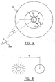
- Stray light may be defined by means of the equivalent luminance (L eq ), which is defined as the background luminance (in cd/m 2 ) that has the same visual effect (e.g. the same adaptive effect on visual sensitivity) as the veil caused by respective stray light sources at some angular distance ⁇ ( figure 3 or figure 4 ).
- the equivalent luminance is divided by the illuminance E gl (in lm/m 2 ) in the plane of the pupil originating from the stray light source.
- the PSF is a function of the angle between glare source and test field.
- One of the benefits of this definition of the stray light parameter is that it is only very weakly dependent on the distance between eye and the stray light source (for example a display device of a stray light meter).
- FIG. 2 shows a computer 1 including a processing unit 2, a storage means 17, for example a hard disk or a memory, a first input terminal 3 for the test subject and a second input terminal 4 for the operator and a display 5 for presentation of stimuli to a subject.
- the display is provided with an enclosure 6 for the purpose of shielding the display 5 from environmental light.
- the enclosure 6 has a headrest 7 in order to ensure a constant distance between eye and display 5.
- the stimuli are presented on a CRT or equivalent display device.
- the stimuli are generated by a processing unit and presented on the display 5.
- a second display device 8 is available for the operator.
- the first input terminal comprises two response buttons 9,10 for collecting responses from the subject to the stimuli provided. These buttons are connected to the personal computer via a suitable interface (for example a Universal Serial Bus interface). The responses can thus be sent to the processing unit. Based on the received responses from the subject and the stimuli shown on the display the processing unit is able to determine the stray light parameter s, as will be described hereafter.
- the luminance (i.e. the physical measure of the amount of light an object sends out) of a display device for example a CRT
- the luminance RGB-code which is a number between 0 and 255 for an 8 bit DAC
- a photodiode suitable for this purpose is a UDT PIN-10AP, manufactured by United Detector Technology Inc. Santa Monica, California, URSA.
- the photodiode is arranged close to or on the display device so as to avoid external influences, for example ambient light, as much as possible.
- the luminance of the display device is measured by integrating the current from the photodiode during one frame of the display device.
- An integrator suitable for this purpose is the TI IVC102, manufactured by Texas Instruments (Burr Brown). The charge, accumulated during a frame, is measured and converted after each frame to a 16-bit digital code.
- the corresponding digital luminance code is transferred to the personal computer 1 via the USB interface.
- a parallel interface may be used.
- noise is added to the luminance code of each pixel independently. It is of importance to create more than 256 intensity values, because the straylight corresponds to about 1 % of the maximal luminance of the display in case of young subjects with normal levels of stray light.
- the stray light source is an annulus.
- This fraction f L eq / c is the ratio between the compensation luminance needed in the center and the luminance of the annulus.
- the luminance in the centre and the luminance in the annulus need to be calibrated. It suffices to establish what fraction f of the luminance in the center originates from the luminance in the annulus. In fact, each value of the fraction f can directly be translated in the straylight parameter s according to this formula.
- an analogue cathode ray tube (CRT) display device use is made of an analogue cathode ray tube (CRT) display device.
- the display device is of the Digital Light Processing (DLPTM) type, wherein digital images can be provided.
- DLPTM Digital Light Processing
- a suitable DLP device is for example the Texas Instruments, type DMD 0.7 XGA DDR).
- DMD digital micro mirror device
- This type of display device use is made of a projection lamp and a digital micro mirror device (DMD) consisting of an array of thousands small-sized mirrors, each mounted on a hinge structure so that it can be individually tilted back and forth.
- the DLP type display device processes the digital input signal and tilts the mirrors to directly generate a digital image.
- One of the advantages of a DLP is that no calibration step is needed. Furthermore, the DLP device is more compact than a computer monitor and is able to provide higher luminances.
- test field is subdivided into two or more spatially separated sections (simultaneous comparisons) and/or into two or more temporally separated sections (sequential comparisons).
- test field sections are hereafter referred to as test fields.
- the test fields are overcompensated or under compensated, giving relatively large modulation depths, such that the resulting flickering is relatively easily perceived, even for untrained subjects.
- the invention will be described for the simple case of a comparison of two test field sections or test fields only, but multiple test fields are also included in the invention.
- Figure 3 shows a preferred embodiment of a circle symmetric stimulus configuration displayed on the display device.
- a stimulus field layout comprising an outer ring 12 simulating a flickering stray light source.
- a test circle 13 surrounded, by a ring 14.
- This is a high intensity ring shaped light source surrounding the test circle in order to isolate the test circle from other parts of the display area and to suppress flicker influences from the surround area.
- the area abutting the stray light source ring 12 on the inside is called the inner periphery or surroundings 19 of the ring 12, while the area outside the ring 12 is called the outer periphery or surroundings 18.
- Steady light in the surroundings (areas 18 and 19) is applied to suppress flicker stimulation in those areas.
- the intensity is preferably of the same order as that of the straylight annulus.
- the test circle 13 is in the present embodiment subdivided in a left half circle or left test field 15 and a right half circle or right test field 16.
- the subject is presented simultaneously with an undercompensated test field and an overcompensated test field.
- the undercompensated test field can be either the left test field 15 or the right test field 16. In case the undercompensated field is the left test field 15, the right test field 16 is overcompensated, while if the undercompensated test field is the right test field 16, the left test field 16 is overcompensated.
- the undercompensated and overcompensated test fields are interchanged arbitrarily during the presentation of consecutive stimuli, i.e. the undercompensated field and the overcompensated field may be shown at random in the left test field 15 or in the right test field 16.
- the test fields are referred to as left test field 15 and right test field 16, in fact reference is made to a first test field (a) and a second test field (b), which may at random be the right and left test field.
- the stimuli are presented with a frequency of preferably 8-10 Hz (since people appear to be relatively sensitive to flicker at this frequency) and with a finite duration, typically between 0,5 and 5 seconds, preferably about 1 second.
- a random or pseudo random algorithm determines which side of the field represents the overcompensated test field and which side of the field represents the undercompensated test field.
- a maximum likelihood algorithm is used to detect a reversal, i.e. when there is statistical significance that the subject has reached the rapid transition located at twice the s value of the eye, and the decrement in overcompensation stops. At this time, there is an initial estimate of the s value of the eye. Based on this value the measurement is refined by presenting stimuli near the reversal point.
- the number of stimuli presented in this second phase of the test, as well as the width of the interval tested, can be chosen prior to the test.
- the order in which the stimuli are presented is chosen randomly, in accordance with the method of constant stimuli.
- measurement accuracy increases with the number of trials in the second phase.
- all data from the test are used in a maximum likelihood fit. This fit gives the final estimate of the reversal point.
- the maximum likelihood procedure gives an estimate of the accuracy of the obtained s value. This estimate of the accuracy is reported to the operator as feedback, such that, in case a subject did not completely understand the visual task, the test can be better explained. All relevant data, such as subject responses, date/time, the time that the system has been on, and the calibration data are automatically stored on the storage means 17 of the computer 1.
- the undercompensated test field is kept at zero compensation, while the overcompensated test field has a variable overcompensation.
- the annulus shaped stray light source flickers with maximum achievable modulation depth. This measurement set-up is shown at P2 in figure 6A.
- Figure 6A shows the retinal flicker in the eye during a flicker comparison measurement.
- the markers show equal retinal flicker for this level of over-/under compensation. Points of equal retinal flicker are indicated with arrows.
- the point of symmetry -where the V-shape has its minimum, in this case zero, value- corresponds to the stray light s value of the eye being measured.
- the left test field 15, or, for the reasons stated earlier, rather a test field (a), is undercompensated with zero compensation and therefore has a retinal flicker intensity I 1 .
- the compensation is varied.
- the point at which the retinal flicker intensity of the right test field 16 equals the retinal flicker intensity I 1 of the non-compensated left test field 15 defines twice the value of the stray light parameter s, as can be clearly seen in figure 6a .
- test field (b) is not compensated, which in fact is only one form of undercompensation. Other forms are more or less undercompensation.
- the general rule for interpretation of the point along the s scale where the two half fields appear equal is that s for the respective subject equals half the sum of s in the two half fields. This can be understood from figure 6a .
- the left test field 15 may be further undercompensated, for example as is shown at P1 in case of in-phase modulation in half field (b), or less undercompensated, for example as is shown at P3 in case of a 0,5 s counterphase modulation in half field (b).
- the values of equal retinal flicker may be higher or lower than the intensity I 1 , as is shown in figure 6A .
- the value of the stray light parameter s may be derived from the V-shaped curve in a similar way by determining the point of symmetry of the curve. This point will give the value of the stray light parameter s.
- a psychometric function describes the chance of a certain response of the subject (e.g. "the left half of the test field flickers stronger than the right half") to a presented stimulus.
- the psychometric space span is 2-dimensional.
- one of the stimuli is constant and each pair of stimuli can be treated as one stimulus value, by considering only the variable modulation depth.
- Figure 6b shows an example of this psychometric function, containing the probability of the response that "field a flickers stronger than field b" for the case that no compensation is present in field (b).
- the psychometric function results in a fit giving in this instance a final estimate of a reversal point that is located at two times the s of the eye, as can clearly be derived from figures 6a and 6b .
- This psychometric curve has some similarities and some peculiar differences with psychometric curves known from other visual tests, e.g. the curve corresponding to a yes-no task in visual field testing.
- the curve has a high value for large overcompensation, and has a rapid transition to a low value at an overcompensation of twice the s of the eye. This rapid transition is used to measure the amount of light scatter in an eye.
- the curve shows a transition to high values again. This shape of the psychometric curve is clearly shown in figure 6b .
- a staircase procedure instead of the two phase measurement technique described above can be used to determine which stimulus level to present.
- this staircase procedure has an initial stepsize of 0.3 log(s) units, and gets a smaller stepsize after each reversal.
- the algorithm that determines the next stimulus level is described in literature as the Accelerated Stochastic Approximation" (see for example the article “ Minireview Adaptive Psychological Procedures” by Bernhard Treutwein, Vision Res., Vol. 35, No. 17 pages 2503-2522, 1995 ) .
- an offset in either the under compensation or overcompensation test field which depends on the amount of under- and overcompensation for that particular stimulus, is added in order to ensure that the subjects gets no clues to detect a difference between the two test fields, other than a difference in the amount of flicker.
- the parameters in the two test fields in particular the average luminance of the test fields, are kept to be the same as much as possible.
- the amounts of overcompensation and undercompensation in the respective test fields are kept at a constant level, while the amount of perceived flicker is varied by altering the intensity of the flickering stray light source.
- the surroundings of the stray light source (referred to as periphery) have a luminance equal to the level of the stray light source.
- the test starts at low luminance levels (stray light source as well as periphery) and gradually becomes brighter, making the comparison task more difficult. This would be in accordance with real life situations, where a brighter stray light source will make detection of a low level target object more difficult.
- the measurement is started with a flicker comparison task, as in the previous embodiments, but without a flickering stray light source.
- flicker detection threshold measurement it is possible to determine the subject's ability to detect flicker (flicker sensitivity).
- the second phase of the test is similar to the second phase in the "dark version" embodiment. This part is used to find the reversal point, as described in the light version embodiment.
- the third phase of the test is the second phase of the light version embodiment, which entails presentation of stimuli around the reversal point, according to the method of constant stimuli, with a stray light source flickering at maximum intensity.
- test fields and/or the stray light source and/or the periphery have different colours, especially the colours blue, green and red.
- the colours may be provided in any combination (e.g. green stray light source, green test fields, white periphery).
- green stray light source, green test fields, white periphery e.g. green stray light source, green test fields, white periphery.
- the stray light parameter in dependence of the wavelength may give useful information on the functioning of the eye.
- input terminal 3 is provided with a third response button. By pressing this response button the subject may indicate that the result of the comparison was undecided (no-choice possibility).
- the angle theta of the stray light source may be changed, for example from 10 degrees to 3 degrees. Especially for driver testing purposes a theta of 3 degrees appears to be most relevant. Different parts of the eye that contribute to stray light have different angular dependencies. Hence, a comparison of the straylight result for different angles provides information about the relative weights of different parts of the eye for their contribution to the total stray light. This can be of relevance for clinical diagnosis or for judging more precisely what stray light hindrance to expect in particular situations. For example, an oncoming car is localized typically at 3 degrees, so its hindrance depends more on straylight at 3 degrees.
- the angular dependence of the straylight contribution from the transparency of the eye wall is know to be isotropic as opposed to the other components. So a measurement of the angular dependence can be used to estimate de relative contribution of such component.
- the most straight forward way of measurement would be to use a straylight annulus located at angle of interest.
- the angle of the annulus can simply be varied, and the straylight parameter measured for different angles separately.
- combinations of angles may be of interest to establish directly the ratios between them.
- the shape of the flicker signal may also be changed.
- a sinusoidal or a triangular wave shape may be beneficial for certain specific applications as just explained, since these waveforms comprise different frequencies.
- the stimuli are separated temporally as opposed to the embodiments employing a spatial separation described so far.
- the overcompensation and under compensation test fields are presented one after the other at the same complete circular test field spot, instead of presentation in two half circular spots at the same time. Flicker sensitivity depends on size of test field. With two half fields, sensitivity is lost as compared to one full circular field. Depending on the application the benefit of simultaneous comparison may be out-weighted by this effect.
- the geometry of the stray light source may be adapted depending on the specific purpose of the stray light measurement.
- Figure 8 shows another preferred embodiment wherein one or more bright point sources are used instead of a ring-shaped source. This may correspond better to specific hindrance situations, such as during driving at night.
- the stray light annulus may be changed in shape, especially, decreased in width. This is of interest if better angular resolution is needed.
- the outer radius is twice the inner radius of the annulus.
- An example of such application is the measurement of the so-caller lenticular halo. This phenomenon, relevant as a pre-phase of cataract, is characterised by a sharp peak in straylight at a few degrees of visual angle.
- different types of stray light sources may be used, such as for example LED's, and/or other types of compensation light sources may be used.
- the light from the stray light source is aimed at the blind spot in the eye.
- the stray light is in this case not or at least less perceived and less disturbing for the test person and therefore for the outcome of the measurements.
- the size of the test field itself may influence the outcome of the determination of the stray light parameter.
- the size of the test field influences sensitivity as well as angular resolution. With increasing size, sensitivity improves but resolution decreases. Depending on the application an optimal balance between these two effects can be obtained.
- test fields are presented on the display device in order to present three or more alternative choices to the subject for spatially as well as temporally separated stimuli.
- the psychometric approach determines speed and accuracy of measurement. Speed of measurement may be increased by multiple simultaneous comparisons. But this task will be more demanding on the subjects. Consequently, this embodiment will be used for specific subject groups only.
- the duration of the stimulus is varied, for example from the preferred duration of about 1 second to for example 10 seconds or more.
- the response time within which the subject has to answer may be varied as well. This variation can be used to optimise subject performance. Some subjects may improve their performance when presentation time is lengthened whereas others may loose on their performance. Individual adaptation of presentation and response times may dynamically be accomplished, guided by the actually measured performance of the subject.
- the image presented in between measurements may have the same average luminance as the luminance presented during the tests.
- the image may be black or may have a maximum intensity. This determines the pre-adaptation state for the presentation. This can be optimised for best performance during the presentation.
- a non-uniform compensation field can be used to more accurately mimic the straylight distribution in the test field. Since stray light depends strongly on angle, the straylight distribution in the test field also shows some non-uniformity, depending on geometry of the straylight source.
- the present invention also contemplates all combinations of the above-described preferred embodiments. For example combinations of either the light or dark version embodiments with all types of different psychophysical measurement techniques (e.g.: method of adjustment, method of constant stimuli, fixed step staircase, stochastic approximation, accelerated stochastic approximation, and maximum likelihood procedures) are feasible.
- the invention also includes all of the above with different variations of over- and undercompensation. For instance:
Landscapes
- Life Sciences & Earth Sciences (AREA)
- Health & Medical Sciences (AREA)
- Medical Informatics (AREA)
- Biophysics (AREA)
- Ophthalmology & Optometry (AREA)
- Engineering & Computer Science (AREA)
- Biomedical Technology (AREA)
- Heart & Thoracic Surgery (AREA)
- Physics & Mathematics (AREA)
- Molecular Biology (AREA)
- Surgery (AREA)
- Animal Behavior & Ethology (AREA)
- General Health & Medical Sciences (AREA)
- Public Health (AREA)
- Veterinary Medicine (AREA)
- Eye Examination Apparatus (AREA)
Claims (44)
- Verfahren zum Messen des retinalen Streulichts in dem Auge einer Testperson, das die folgenden Schritte umfasst:• der Testperson ein flackerndes Streulicht aus einer Streulichtquelle zu präsentieren, die in einer vorgegebenen Winkelentfernung von einem Testgebiet positioniert ist, wobei ein Teil des flackernden Streulichts auf der Retina an einem Ort abgebildet wird, der dem Ort des Testgebiets entspricht;• der Testperson ein Kompensationslicht aus einer Kompensationslichtquelle zu präsentieren, die an einer Position in dem Testgebiet angeordnet ist, wobei die Parameter des Kompensationslichts so eingestellt sind, dass sie sofort oder letztendlich den Teil des flackernden Streulichts unterkompensieren, der auf der Retina an dem Ort, der dem Ort des Testgebiets entspricht, abgebildet wird;• der Testperson ein Kompensationslicht aus einer Kompensationslichtquelle zu präsentieren, die an einer Position in dem Testgebiet angeordnet ist, wobei die Parameter des Kompensationslichts so eingestellt sind, dass sie sofort oder letztendlich den Teil des flackernden Lichts überkompensieren, der auf der Retina an dem Ort, der dem Ort des Testgebiets entspricht, abgebildet wird;dadurch gekennzeichnet, dass es weiter die folgenden Schritte umfasst:• Empfangen eines Eingangssignals, das für das Ergebnis eines Vergleichs zwischen dem resultierenden retinalen Lichtflackern, wie es durch die Testperson für das unterkompensierte Testgebiet wahrgenommen wird, und der resultierenden retinalen Flackerintensität für das überkompensierte Testgebiet repräsentativ ist;• Verändern des Wertes/der Werte von einem oder mehreren der Parameter, die eines oder mehrere von dem Streulichtquellenlicht und dem Kompensationslichtquellenlicht definieren;• Wiederholen der oben genannten Schritte für unterschiedliche Parameterwerte;• Bestimmen, unter Verwendung der empfangenen Eingangssignale und der entsprechenden Parameterwerte der Streulichtquelle und der Kompensationslichtquellen, jener Parameterwerte, bei denen die wahrgenommenen retinalen Lichtintensitäten des unterkompensierten und überkompensierten Testgebiets im Wesentlichen gleich sind;• Berechnen aus den bestimmten Parameterwerten eines Streulichtparameters, der für das retinale Streulicht, das durch die Streulichtquelle induziert wird, repräsentativ ist.
- Verfahren gemäß Anspruch 1, wobei in dem ersten Schritt, der Testperson Kompensationslicht aus einer Kompensationslichtquelle zu präsentieren, das Kompensationslicht mit der Streulichtquelle gleichphasig oder gegenphasig ist und mit einer Modulationstiefe, einschließlich einer Modulationstiefe null, versehen ist, sodass es den Teil des flackernden Streulichts, der auf der Retina an dem Ort, der dem Ort des Testgebiets entspricht, abgebildet wird, unterkompensiert;
wobei in dem zweiten Schritt, der Testperson Kompensationslicht aus einer Kompensationslichtquelle zu präsentieren, das Kompensationslicht mit einer Modulationstiefe flackert, sodass es letztendlich den Teil des flackernden Lichts, der auf der Retina an dem Ort, der dem Ort des Testgebiets entspricht, abgebildet wird, überkompensiert;
wobei, unter Verwendung der Ergebnisse der Wiederholungen und basierend auf den Eingangssignalen, die Modulationstiefen der Streulichtquelle, des unterkompensierten Testgebiets und des überkompensierten Testgebiets bestimmt werden, wo die wahrgenommenen retinalen Lichtintensitäten des unterkompensierten und überkompensierten Testgebiets im Wesentlichen gleich sind; und
wobei aus den bestimmten Modulationstiefen ein Streulichtparameter, der für das retinale Streulicht repräsentativ ist, bestimmt wird. - Verfahren gemäß Anspruch 1 oder 2, wobei der Parameter, der variiert wird, die Modulationstiefe des Lichts aus der Streulichtquelle ist.
- Verfahren gemäß einem der vorhergehenden Ansprüche, wobei der Parameter, der variiert wird, die Modulationstiefe des Kompensationslichts für mindestens eines der unterkompensierten und überkompensierten Testgebiete ist.
- Verfahren gemäß Anspruch 4, wobei das periphere Licht aus dem Umfeld (18, 19) der Streulichtquelle eine Luminanz aufweist, die der Luminanz der Streulichtquelle im Wesentlichen gleich ist.
- Verfahren gemäß einem der Ansprüche 1 bis 5, wobei das erste und zweite Kompensationslicht zeitlich aufeinanderfolgend präsentiert werden.
- Verfahren gemäß einem der Ansprüche 1 bis 5, wobei das erste und zweite Kompensationslicht gleichzeitig präsentiert werden.
- Verfahren gemäß Anspruch 7, wobei das Testgebiet mindestens ein erstes und ein zweites Testfeld umfasst, die räumlich getrennt sind, und wobei eine erste Kompensationslichtquelle an dem Ort des ersten Testfelds angeordnet ist und eine zweite Kompensationslichtquelle an dem Ort des zweiten Testfelds angeordnet ist.
- Verfahren gemäß Anspruch 8, dass nach dem Empfang des Eingangssignals folgende Schritte umfasst:• Verändern der summierten Modulationstiefe des Kompensationslichts des unterkompensierten Testfelds und des überkompensierten Testfelds, während eine konstante Differenz zwischen den Modulationstiefen des unterkompensierten und überkompensierten Testfelds beibehalten wird;• Wiederholen der Präsentationsschritte und des Empfangsschritts unter Verwendung der veränderten summierten Modulationstiefe, bis die Modulationstiefe bestimmt wird, bei welcher die wahrgenommenen retinalen Lichtintensitäten des unterkompensierten und überkompensierten Testgebiets im Wesentlichen gleich sind.
- Verfahren gemäß einem der vorhergehenden Ansprüche, wobei entweder in dem Unterkompensations- oder Überkompensationstestfeld ein Versatz addiert wird, wobei der Versatz von der Menge an Unter- und Überkompensation für einen speziellen Reiz abhängt.
- Verfahren gemäß Anspruch 10, wobei die durchschnittliche Luminanz des unterkompensierten Testfelds so eingestellt wird, dass sie der durchschnittlichen Luminanz des überkompensierten Testfelds, das zur gleichen Zeit präsentiert wird, entspricht.
- Verfahren gemäß einem der vorhergehenden Ansprüche, das den Schritt des Präsentierens von Kompensationslicht in einem oder mehreren der Testfelder ohne Präsentieren von Licht aus der Streulichtquelle umfasst, um so die Erfassungsschwelle für flackerndes Licht der Testperson zu bestimmen.
- Verfahren gemäß Anspruch 12, wobei das Bestimmen der Erfassungsschwelle für flackerndes Licht der Testperson die folgenden Schritte umfasst• Präsentieren von Kompensationslicht variierender Modulationstiefendifferenzen in den Testfeldern ohne Präsentieren von Licht aus der Streulichtquelle; und• Bestimmen des Werts der minimalen Modulationstiefendifferenz, der durch die Testperson bemerkt werden kann.
- Verfahren gemäß einem der vorhergehenden Ansprüche, das Folgendes umfasst:• Bestimmen einer ersten Schätzung des Streulichtparameters durch Verwendung des Verfahrens des Veränderns des Lichts von der Streulichtquelle;• Bestimmen einer zweiten Schätzung des Streulichtparameters durch Verwendung des Verfahrens des Veränderns der Modulationstiefe von mindestens einem der Testfelder, wobei die Modulationstiefen, die präsentiert werden, auf der ersten Schätzung des Streulichtparameters basieren.
- Verfahren gemäß Anspruch 4 und 13, wobei die Streulichtquelle flackerndes Licht mit einer maximalen Intensität präsentiert.
- Verfahren gemäß einem der vorhergehenden Ansprüche, wobei die Streulichtquelle eine ringförmige Form aufweist.
- Verfahren gemäß einem der Ansprüche 1 bis 16, wobei die Streulichtquelle eine oder mehrere Punktlichtquellen umfasst.
- Verfahren gemäß einem der vorhergehenden Ansprüche, wobei das Testgebiet eine kreisförmige Form, bevorzugt in zwei gleiche Teile geteilt, umfasst.
- Verfahren gemäß Anspruch 18, wobei das Testgebiet in dem Mittelpunkt des Ringes gelegen ist und der Streulichtparameter s definiert ist als:

- Verfahren gemäß einem der vorhergehenden Ansprüche, wobei eine ringförmige Hochintensitätslichtquelle, welche das Testgebiet umgibt, zum Isolieren des Testgebiets vom Umfeld bereitgestellt wird.
- Verfahren gemäß einem der vorhergehenden Ansprüche, wobei die Streulichtquelle durch lichterfüllte Gebiete, wie etwa ein äußeres Gebiet (18) und ein inneres Gebiet (19), umgeben ist, um Flackern in jenen Gebieten zu unterdrücken.
- Verfahren gemäß einem der vorhergehenden Ansprüche, wobei die Testfelder und/oder die Streulichtquelle mit unterschiedlichen Farben präsentiert werden, um den Streulichtparameter in Abhängigkeit von der Wellenlänge des Streulichts zu bestimmen.
- Verfahren gemäß einem der vorhergehenden Ansprüche, wobei das retinale Streulicht in beiden Augen einer Testperson gleichzeitig bestimmt wird.
- Verfahren gemäß einem der vorhergehenden Ansprüche, wobei zwischen aufeinanderfolgenden Präsentationen von Streulicht und Kompensationslicht ein Bild zur Voradaption präsentiert wird.
- Verfahren gemäß Anspruch 24, wobei das Bild eine durchschnittliche Luminanz aufweist, die jener der durchschnittlichen Luminanz während der Präsentationen entspricht.
- Verfahren gemäß einem der vorhergehenden Ansprüche, das weiter den Schritt des Speicherns relevanter Daten, wie etwa Testpersoneneingabe, Datum und Zeit, umfasst.
- Verfahren gemäß einem der vorhergehenden Ansprüche, wobei das Testgebiet mit unscharfen Rändern versehen wird.
- Verfahren gemäß einem der vorhergehenden Ansprüche, wobei variable Versätze in den Testfeldern des Tests bereitgestellt werden.
- Verfahren gemäß einem der vorhergehenden Ansprüche, wobei die Unterkompensation und Überkompensation der Testfelder räumlich moduliert werden.
- Verfahren gemäß Anspruch 29, wobei die räumliche Modulation ungefähr 2 bis 4 Zyklen/Grad beträgt.
- Verfahren gemäß einem der vorhergehenden Ansprüche, wobei das Licht von der Streulichtquelle auf den blinden Fleck in dem Auge gerichtet ist.
- Verfahren gemäß einem der vorhergehenden Ansprüche, wobei die Dauer der Präsentation des Lichts von der Streulichtquelle und mindestens einer Kompensationslichtquelle verändert wird.
- Verfahren gemäß einem der vorhergehenden Ansprüche, wobei die Antwortzeit, innerhalb derer die Versuchsperson das Ergebnis ihres Vergleichs bereitzustellen hat, verändert wird.
- Verfahren gemäß einem der vorhergehenden Ansprüche, wobei der Winkel (θ) der Streulichtquelle verändert wird.
- Verfahren gemäß einem der vorhergehenden Ansprüche, wobei die Flackerfrequenz der Kompensationslichtquelle und/oder der Streulichtquelle verändert wird.
- Verfahren gemäß einem der vorhergehenden Ansprüche, wobei das Testfeld ein ungleichförmiges Testgebiet aufweist.
- Vorrichtung zum Messen der optischen Klarheit des Auges einer Versuchsperson, die Folgendes umfasst• ein erstes Anzeigemittel, um der Testperson ein flackerndes Streulicht aus einer Streulichtquelle zu präsentieren, die in einer vorgegebenen Winhelentfernung von einem Testgebiet angeordnet ist, wobei ein Teil des flackernden Streulichts auf der Retina an einem Ort, der dem Ort des Testgebiets entspricht, abgebildet wird;• ein zweites Anzeigemittel, um der Testperson Kompensationslicht aus einer Kompensationslichtquelle zu präsentieren, die an einer Position in dem Testgebiet angeordnet ist, wobei die Parameter des Kompensationslichts so eingestellt werden, dass es sofort oder letztendlich den Teil des flackernden Streulichts unterkompensiert, der auf der Retina an dem Ort, der dem Ort des Testgebiets entspricht, abgebildet wird;• ein drittes Anzeigemittel, um der Testperson Kompensationslicht aus einer Kompensationslichtquelle zu präsentieren, die an einem Ort in dem Testgebiet angeordnet ist, wobei die Parameter des Kompensationslicht so eingestellt werden, dass es sofort oder letztendlich den Teil des flackernden Lichts überkompensiert, der auf der Retina an dem Ort, der dem Ort des Testgebiets entspricht, abgebildet wird;dadurch gekennzeichnet, dass die Vorrichtung weiter umfasst:• Eingabemittel zum Empfangen eines Eingangssignals, das für das Ergebnis eines Vergleichs zwischen der resultierenden retinalen Flackerintensität, wie sie durch die Testperson für das unterkompensierte Streulicht wahrgenommen wird, und der resultierenden retinalen Flackerintensität für das überkompensierte Streulicht repräsentativ ist;• ein erstes Verarbeitungsmittel zum Verändern des Werts oder der Werte von einem oder mehreren der Parameter, die mindestens eines der Lichter von dem ersten, zweiten und dritten Anzeigemittel definieren;• ein zweites Verarbeitungsmittel zum Bestimmen der Parameterwerte des Lichts von der Streulichtquelle, dem unterkompensierten Testgebiet und dem überkompensierten Testgebiet, wobei die wahrgenommenen retinalen Lichtintensitäten des unterkompensierten und überkompensierten Testgebiets im Wesentlichen gleich sind;• ein drittes Verarbeitungsmittel zum Berechnen aus den bestimmten Parameterwerten eines Streulichtparameters, der für das retinale Streulicht, das durch die Streulichtquelle induziert wird, repräsentativ ist.
- Vorrichtung gemäß Anspruch 37, wobei das erste Kompensationslicht gleichphasig oder gegenphasig mit der Streulichtquelle ist und mit einer Modulationstiefe, einschließlich einer Modulationstiefe null, versehen ist, sodass es den Teil des flackernden Streulichts unterkompensiert, der auf der Retina an dem Ort, der dem Ort des Testgebiets entspricht, abgebildet wird;• das zweite Kompensationslicht mit einer Modulationstiefe flackert, sodass es den Teil des flackernden Lichts überkompensiert, der auf der Retina an dem Ort, der dem Ort des Testgebiets entspricht, abgebildet wird;• wobei das zweite Verarbeitungsmittel so betreibbar ist, dass es, unter Verwendung der Ergebnisse der Wiederholung und des Eingangssignals, die Modulationstiefen der Streulichtquelle, des unterkompensierten Testgebiets und des überkompensierten Testgebiets bestimmen kann, wobei die wahrgenommenen retinalen Lichtintensitäten des unterkompensierten und überkompensierten Testgebiets im Wesentlichen gleich sind; und• das dritte Verarbeitungsmittel so betreibbar ist, dass es den Streulichtparameter aus den bestimmten Modulationstiefen berechnet.
- Vorrichtung gemäß Anspruch 37 oder 38, wobei das Anzeigemittel eine Einfassung umfasst, die das Anzeigemittel von Umgebungslicht abschirmt.
- Vorrichtung gemäß Anspruch 37, wobei das Eingabemittel mindestens zwei Antwortknöpfe zum Sammeln von Antworten von der Versuchsperson auf die dargestellten Reize umfasst.
- Vorrichtung gemäß einem der Ansprüche 37 bis 40, wobei das erste und zweite Verarbeitungsmittel durch einen Computer gebildet werden.
- Vorrichtung gemäß einem der Ansprüche 37 bis 41, wobei das Anzeigemittel eine Kathodenstrahlröhren(CRT)-Vorrichtung oder eine Anzahl von Licht emittierenden Dioden(LED)-Vorrichtungen umfasst.
- Vorrichtung gemäß einem der Ansprüche 37 bis 42, wobei das Anzeigemittel eine digitale Lichtverarbeitungs(DLP)-Vorrichtung umfasst.
- Vorrichtung gemäß einem der Ansprüche 37 bis 43, wobei das Anzeigemittel, Eingabemittel und Verarbeitungsmittel zum Ausführen des Verfahrens gemäß einem der Ansprüche 1 bis 36 geeignet sind.
Applications Claiming Priority (2)
| Application Number | Priority Date | Filing Date | Title |
|---|---|---|---|
| NL1024232A NL1024232C2 (nl) | 2003-09-05 | 2003-09-05 | Werkwijze en inrichting voor het meten van retinaal strooilicht. |
| PCT/NL2004/000569 WO2005023103A1 (en) | 2003-09-05 | 2004-08-12 | Method and device for measuring retinal stray light |
Publications (2)
| Publication Number | Publication Date |
|---|---|
| EP1659929A1 EP1659929A1 (de) | 2006-05-31 |
| EP1659929B1 true EP1659929B1 (de) | 2015-07-22 |
Family
ID=34270801
Family Applications (1)
| Application Number | Title | Priority Date | Filing Date |
|---|---|---|---|
| EP04774876.9A Expired - Lifetime EP1659929B1 (de) | 2003-09-05 | 2004-08-12 | Verfahren und vorrichtung zur messung von retinalem streulicht |
Country Status (5)
| Country | Link |
|---|---|
| US (1) | US7673991B2 (de) |
| EP (1) | EP1659929B1 (de) |
| JP (1) | JP4823062B2 (de) |
| NL (1) | NL1024232C2 (de) |
| WO (1) | WO2005023103A1 (de) |
Families Citing this family (18)
| Publication number | Priority date | Publication date | Assignee | Title |
|---|---|---|---|---|
| US9248047B2 (en) * | 2006-01-23 | 2016-02-02 | Ziemer Holding Ag | System for protecting tissue in the treatment of eyes |
| CN100587443C (zh) * | 2006-11-07 | 2010-02-03 | 中国科学院西安光学精密机械研究所 | 基于计算机全息光学元件的大口径杂光系数测试方法及其系统 |
| JP2009031441A (ja) * | 2007-07-25 | 2009-02-12 | Sony Corp | 投射型表示装置 |
| RU2348343C1 (ru) * | 2007-08-14 | 2009-03-10 | Государственное учреждение "Курганский областной госпиталь ветеранов войн" | Способ ранней диагностики изменений в сетчатке при метаболическом синдроме |
| WO2011091804A1 (en) | 2010-01-29 | 2011-08-04 | Tartu Ülikool (University Of Tartu) | An apparatus for quantitative cataract diagnostics |
| JP5646870B2 (ja) * | 2010-04-14 | 2014-12-24 | 一夫 市川 | 色覚検査装置、制御プログラム、及び前記色覚検査装置の制御方法 |
| US9030657B2 (en) * | 2010-07-14 | 2015-05-12 | William P. Kuhn, Ph.D., Llc | Device and method for subaperture stray light detection and diagnosis |
| ES2391192B2 (es) * | 2011-04-28 | 2013-06-18 | Universidad De Murcia | Procedimiento y sistema para la medida de la difusión intraocular. |
| JP6411757B2 (ja) * | 2014-03-17 | 2018-10-24 | 国立大学法人豊橋技術科学大学 | 表面欠陥検査員の検査能力判定装置および検査能力判定方法 |
| JP6586597B2 (ja) * | 2015-02-04 | 2019-10-09 | 株式会社トーメーコーポレーション | 眼科検査装置 |
| WO2017121466A1 (de) * | 2016-01-12 | 2017-07-20 | Deutsche Augenoptik AG | Verfahren zur sehzeichendarstellung, sehzeichengerät, und rahmen zur befestigung an einem sehzeichengerät |
| EP3685145B1 (de) | 2017-09-19 | 2024-01-03 | Beckman Coulter, Inc. | System zur analogen lichtmessung und photonenzählung in chemilumineszenzmessungen |
| FR3083975B1 (fr) * | 2018-07-20 | 2020-10-16 | Univ Sorbonne | Dispositif d'observation oculaire |
| CN110420009B (zh) * | 2019-08-30 | 2021-09-21 | 北京大学第三医院(北京大学第三临床医学院) | 一种针对不同感光细胞动态视觉刺激视标测试系统 |
| CN111035358B (zh) * | 2019-12-28 | 2022-03-11 | 重庆贝奥新视野医疗设备有限公司 | 一种眼底照相机的消杂光系统及其工作方法 |
| EP3881752B1 (de) * | 2020-03-20 | 2025-08-13 | Essilor International | System zur bestimmung eines subjektiven wertes eines optischen merkmals von mindestens einer korrekturlinse, die an ein auge einer person angepasst ist, und zugehöriges verfahren |
| DE102021105586B3 (de) | 2021-03-09 | 2022-05-19 | Technische Universität Ilmenau | Verfahren und Vorrichtung zur objektiven elektrophysiologischen Bestimmung des wahrgenommenen Streulichts des menschlichen Auges |
| CN115147293B (zh) * | 2022-05-25 | 2025-03-25 | 国家卫星气象中心(国家空间天气监测预警中心) | 一种晨昏轨道卫星微光通道杂散光去除方法及装置 |
Family Cites Families (9)
| Publication number | Priority date | Publication date | Assignee | Title |
|---|---|---|---|---|
| JP2618912B2 (ja) * | 1987-08-31 | 1997-06-11 | 興和株式会社 | 眼底検査装置 |
| JPH02119837A (ja) * | 1988-10-28 | 1990-05-07 | Kowa Co | 眼科測定方法および装置 |
| US5284149A (en) * | 1992-01-23 | 1994-02-08 | Dhadwal Harbans S | Method and apparatus for determining the physical characteristics of ocular tissue |
| US5671039A (en) * | 1992-10-19 | 1997-09-23 | Leica Inc. | Glare tester |
| US5632282A (en) * | 1993-07-20 | 1997-05-27 | Hay; S. Hutson | Ocular disease detection apparatus |
| DE69609363T2 (de) * | 1995-02-02 | 2001-01-04 | Nidek Co., Ltd. | Ophthalmologisches Messgerät |
| JP3396554B2 (ja) * | 1995-02-02 | 2003-04-14 | 株式会社ニデック | 眼科測定装置 |
| KR100237686B1 (ko) * | 1997-11-06 | 2000-01-15 | 윤종용 | 플리커 레벨 측정 방법 및 장치 |
| JP4199000B2 (ja) * | 2001-03-15 | 2008-12-17 | エイエムオー・ウェーブフロント・サイエンシーズ・リミテッド・ライアビリティ・カンパニー | 光学システムをマッピングするための断層撮影波面分析システム及び方法 |
-
2003
- 2003-09-05 NL NL1024232A patent/NL1024232C2/nl not_active IP Right Cessation
-
2004
- 2004-08-12 US US10/570,676 patent/US7673991B2/en not_active Expired - Fee Related
- 2004-08-12 JP JP2006525285A patent/JP4823062B2/ja not_active Expired - Fee Related
- 2004-08-12 WO PCT/NL2004/000569 patent/WO2005023103A1/en not_active Ceased
- 2004-08-12 EP EP04774876.9A patent/EP1659929B1/de not_active Expired - Lifetime
Also Published As
| Publication number | Publication date |
|---|---|
| EP1659929A1 (de) | 2006-05-31 |
| JP4823062B2 (ja) | 2011-11-24 |
| NL1024232C2 (nl) | 2005-03-08 |
| US20070273833A1 (en) | 2007-11-29 |
| WO2005023103A1 (en) | 2005-03-17 |
| JP2007533352A (ja) | 2007-11-22 |
| US7673991B2 (en) | 2010-03-09 |
Similar Documents
| Publication | Publication Date | Title |
|---|---|---|
| EP1659929B1 (de) | Verfahren und vorrichtung zur messung von retinalem streulicht | |
| Abrahamsson et al. | Impairment of contrast sensitivity function (CSF) as a measure of disability glare. | |
| JP4464726B2 (ja) | 眼科装置 | |
| Minkowski et al. | Potential acuity meter using a minute aerial pinhole aperture | |
| CA2438109A1 (en) | Contrast chart apparatus, contrast sensitivity measuring apparatus, and contrast sensitivity measuring method | |
| EP1330979B1 (de) | Vorrichtung und Verfahren zum Bestimmen der Kontrast-Empfindlichkeit | |
| Adhikari et al. | Design and validation of a chart‐based measure of the limits of spatial contrast sensitivity | |
| JP4318463B2 (ja) | 矯正データ測定装置、矯正データ測定プログラム、矯正データ測定プログラムを記録した記録媒体及び眼特性測定装置 | |
| JP4570796B2 (ja) | コントラストチャート装置 | |
| JP4528049B2 (ja) | 眼科装置 | |
| Meikies et al. | Rostock Glare Perimeter: a distinctive method for quantification of glare | |
| JP2003199712A (ja) | コントラスト感度測定装置、コントラスト感度測定方法 | |
| EP2710950B1 (de) | Verfahren und system zur messung der intraokularen streuung | |
| JP2004337236A (ja) | 眼科データ測定装置、眼科データ測定プログラム、眼科データ測定プログラムを記録した記録媒体 | |
| Colombo et al. | What characteristics a clinical CSF system has to have? | |
| CN120282744A (zh) | 确定测试对象的视觉锐度特性的方法、经适配的视标的用途和装置 | |
| US10165943B2 (en) | Ophthalmic method and apparatus for noninvasive diagnosis and quantitative assessment of cataract development | |
| Goyal et al. | Estimation of spherical refractive errors using virtual reality headset | |
| Still | Optical limits to contrast sensitivity in human peripheral vision | |
| Citek | Contrast sensitivity function | |
| Prager | Essential factors in testing for glare | |
| Hess et al. | Amblyopia cannot be explained by considering only detection thresholds | |
| Labhishetty | Accommodative lags and leads: Fact or fiction | |
| Ketomäki | Effects of lighting parameters on contrast threshold in the mesopic and photopic luminance ranges | |
| Tyler | The full range of human temporal resolution |
Legal Events
| Date | Code | Title | Description |
|---|---|---|---|
| PUAI | Public reference made under article 153(3) epc to a published international application that has entered the european phase |
Free format text: ORIGINAL CODE: 0009012 |
|
| 17P | Request for examination filed |
Effective date: 20060303 |
|
| AK | Designated contracting states |
Kind code of ref document: A1 Designated state(s): AT BE BG CH CY CZ DE DK EE ES FI FR GB GR HU IE IT LI LU MC NL PL PT RO SE SI SK TR |
|
| DAX | Request for extension of the european patent (deleted) | ||
| REG | Reference to a national code |
Ref country code: DE Ref legal event code: R079 Ref document number: 602004047538 Country of ref document: DE Free format text: PREVIOUS MAIN CLASS: A61B0003100000 Ipc: A61B0003032000 |
|
| GRAP | Despatch of communication of intention to grant a patent |
Free format text: ORIGINAL CODE: EPIDOSNIGR1 |
|
| RIC1 | Information provided on ipc code assigned before grant |
Ipc: A61B 3/12 20060101ALI20150324BHEP Ipc: A61B 3/10 20060101ALI20150324BHEP Ipc: A61B 5/18 20060101ALI20150324BHEP Ipc: A61B 3/032 20060101AFI20150324BHEP Ipc: A61B 3/06 20060101ALI20150324BHEP |
|
| INTG | Intention to grant announced |
Effective date: 20150415 |
|
| GRAS | Grant fee paid |
Free format text: ORIGINAL CODE: EPIDOSNIGR3 |
|
| GRAA | (expected) grant |
Free format text: ORIGINAL CODE: 0009210 |
|
| AK | Designated contracting states |
Kind code of ref document: B1 Designated state(s): AT BE BG CH CY CZ DE DK EE ES FI FR GB GR HU IE IT LI LU MC NL PL PT RO SE SI SK TR |
|
| REG | Reference to a national code |
Ref country code: GB Ref legal event code: FG4D |
|
| REG | Reference to a national code |
Ref country code: CH Ref legal event code: EP |
|
| REG | Reference to a national code |
Ref country code: IE Ref legal event code: FG4D |
|
| REG | Reference to a national code |
Ref country code: AT Ref legal event code: REF Ref document number: 737396 Country of ref document: AT Kind code of ref document: T Effective date: 20150815 |
|
| REG | Reference to a national code |
Ref country code: DE Ref legal event code: R096 Ref document number: 602004047538 Country of ref document: DE |
|
| REG | Reference to a national code |
Ref country code: AT Ref legal event code: MK05 Ref document number: 737396 Country of ref document: AT Kind code of ref document: T Effective date: 20150722 |
|
| REG | Reference to a national code |
Ref country code: NL Ref legal event code: MP Effective date: 20150722 |
|
| PG25 | Lapsed in a contracting state [announced via postgrant information from national office to epo] |
Ref country code: FI Free format text: LAPSE BECAUSE OF FAILURE TO SUBMIT A TRANSLATION OF THE DESCRIPTION OR TO PAY THE FEE WITHIN THE PRESCRIBED TIME-LIMIT Effective date: 20150722 Ref country code: GR Free format text: LAPSE BECAUSE OF FAILURE TO SUBMIT A TRANSLATION OF THE DESCRIPTION OR TO PAY THE FEE WITHIN THE PRESCRIBED TIME-LIMIT Effective date: 20151023 |
|
| PG25 | Lapsed in a contracting state [announced via postgrant information from national office to epo] |
Ref country code: ES Free format text: LAPSE BECAUSE OF FAILURE TO SUBMIT A TRANSLATION OF THE DESCRIPTION OR TO PAY THE FEE WITHIN THE PRESCRIBED TIME-LIMIT Effective date: 20150722 Ref country code: AT Free format text: LAPSE BECAUSE OF FAILURE TO SUBMIT A TRANSLATION OF THE DESCRIPTION OR TO PAY THE FEE WITHIN THE PRESCRIBED TIME-LIMIT Effective date: 20150722 Ref country code: SE Free format text: LAPSE BECAUSE OF FAILURE TO SUBMIT A TRANSLATION OF THE DESCRIPTION OR TO PAY THE FEE WITHIN THE PRESCRIBED TIME-LIMIT Effective date: 20150722 Ref country code: PT Free format text: LAPSE BECAUSE OF FAILURE TO SUBMIT A TRANSLATION OF THE DESCRIPTION OR TO PAY THE FEE WITHIN THE PRESCRIBED TIME-LIMIT Effective date: 20151123 Ref country code: PL Free format text: LAPSE BECAUSE OF FAILURE TO SUBMIT A TRANSLATION OF THE DESCRIPTION OR TO PAY THE FEE WITHIN THE PRESCRIBED TIME-LIMIT Effective date: 20150722 |
|
| REG | Reference to a national code |
Ref country code: CH Ref legal event code: PL |
|
| REG | Reference to a national code |
Ref country code: DE Ref legal event code: R097 Ref document number: 602004047538 Country of ref document: DE |
|
| PG25 | Lapsed in a contracting state [announced via postgrant information from national office to epo] |
Ref country code: LI Free format text: LAPSE BECAUSE OF NON-PAYMENT OF DUE FEES Effective date: 20150831 Ref country code: IT Free format text: LAPSE BECAUSE OF FAILURE TO SUBMIT A TRANSLATION OF THE DESCRIPTION OR TO PAY THE FEE WITHIN THE PRESCRIBED TIME-LIMIT Effective date: 20150722 Ref country code: CZ Free format text: LAPSE BECAUSE OF FAILURE TO SUBMIT A TRANSLATION OF THE DESCRIPTION OR TO PAY THE FEE WITHIN THE PRESCRIBED TIME-LIMIT Effective date: 20150722 Ref country code: EE Free format text: LAPSE BECAUSE OF FAILURE TO SUBMIT A TRANSLATION OF THE DESCRIPTION OR TO PAY THE FEE WITHIN THE PRESCRIBED TIME-LIMIT Effective date: 20150722 Ref country code: CH Free format text: LAPSE BECAUSE OF NON-PAYMENT OF DUE FEES Effective date: 20150831 Ref country code: DK Free format text: LAPSE BECAUSE OF FAILURE TO SUBMIT A TRANSLATION OF THE DESCRIPTION OR TO PAY THE FEE WITHIN THE PRESCRIBED TIME-LIMIT Effective date: 20150722 Ref country code: MC Free format text: LAPSE BECAUSE OF FAILURE TO SUBMIT A TRANSLATION OF THE DESCRIPTION OR TO PAY THE FEE WITHIN THE PRESCRIBED TIME-LIMIT Effective date: 20150722 Ref country code: SK Free format text: LAPSE BECAUSE OF FAILURE TO SUBMIT A TRANSLATION OF THE DESCRIPTION OR TO PAY THE FEE WITHIN THE PRESCRIBED TIME-LIMIT Effective date: 20150722 |
|
| PLBE | No opposition filed within time limit |
Free format text: ORIGINAL CODE: 0009261 |
|
| STAA | Information on the status of an ep patent application or granted ep patent |
Free format text: STATUS: NO OPPOSITION FILED WITHIN TIME LIMIT |
|
| PG25 | Lapsed in a contracting state [announced via postgrant information from national office to epo] |
Ref country code: RO Free format text: LAPSE BECAUSE OF FAILURE TO SUBMIT A TRANSLATION OF THE DESCRIPTION OR TO PAY THE FEE WITHIN THE PRESCRIBED TIME-LIMIT Effective date: 20150722 |
|
| REG | Reference to a national code |
Ref country code: IE Ref legal event code: MM4A |
|
| 26N | No opposition filed |
Effective date: 20160425 |
|
| PG25 | Lapsed in a contracting state [announced via postgrant information from national office to epo] |
Ref country code: IE Free format text: LAPSE BECAUSE OF NON-PAYMENT OF DUE FEES Effective date: 20150812 |
|
| REG | Reference to a national code |
Ref country code: FR Ref legal event code: PLFP Year of fee payment: 13 |
|
| PG25 | Lapsed in a contracting state [announced via postgrant information from national office to epo] |
Ref country code: SI Free format text: LAPSE BECAUSE OF FAILURE TO SUBMIT A TRANSLATION OF THE DESCRIPTION OR TO PAY THE FEE WITHIN THE PRESCRIBED TIME-LIMIT Effective date: 20150722 |
|
| PGFP | Annual fee paid to national office [announced via postgrant information from national office to epo] |
Ref country code: GB Payment date: 20160830 Year of fee payment: 13 |
|
| PGFP | Annual fee paid to national office [announced via postgrant information from national office to epo] |
Ref country code: FR Payment date: 20160825 Year of fee payment: 13 |
|
| PG25 | Lapsed in a contracting state [announced via postgrant information from national office to epo] |
Ref country code: BG Free format text: LAPSE BECAUSE OF FAILURE TO SUBMIT A TRANSLATION OF THE DESCRIPTION OR TO PAY THE FEE WITHIN THE PRESCRIBED TIME-LIMIT Effective date: 20150722 Ref country code: HU Free format text: LAPSE BECAUSE OF FAILURE TO SUBMIT A TRANSLATION OF THE DESCRIPTION OR TO PAY THE FEE WITHIN THE PRESCRIBED TIME-LIMIT; INVALID AB INITIO Effective date: 20040812 |
|
| PG25 | Lapsed in a contracting state [announced via postgrant information from national office to epo] |
Ref country code: CY Free format text: LAPSE BECAUSE OF FAILURE TO SUBMIT A TRANSLATION OF THE DESCRIPTION OR TO PAY THE FEE WITHIN THE PRESCRIBED TIME-LIMIT Effective date: 20150722 Ref country code: NL Free format text: LAPSE BECAUSE OF FAILURE TO SUBMIT A TRANSLATION OF THE DESCRIPTION OR TO PAY THE FEE WITHIN THE PRESCRIBED TIME-LIMIT Effective date: 20150722 |
|
| PG25 | Lapsed in a contracting state [announced via postgrant information from national office to epo] |
Ref country code: BE Free format text: LAPSE BECAUSE OF NON-PAYMENT OF DUE FEES Effective date: 20150831 |
|
| PG25 | Lapsed in a contracting state [announced via postgrant information from national office to epo] |
Ref country code: TR Free format text: LAPSE BECAUSE OF FAILURE TO SUBMIT A TRANSLATION OF THE DESCRIPTION OR TO PAY THE FEE WITHIN THE PRESCRIBED TIME-LIMIT Effective date: 20150722 |
|
| PG25 | Lapsed in a contracting state [announced via postgrant information from national office to epo] |
Ref country code: LU Free format text: LAPSE BECAUSE OF NON-PAYMENT OF DUE FEES Effective date: 20150812 |
|
| GBPC | Gb: european patent ceased through non-payment of renewal fee |
Effective date: 20170812 |
|
| REG | Reference to a national code |
Ref country code: FR Ref legal event code: ST Effective date: 20180430 |
|
| PG25 | Lapsed in a contracting state [announced via postgrant information from national office to epo] |
Ref country code: GB Free format text: LAPSE BECAUSE OF NON-PAYMENT OF DUE FEES Effective date: 20170812 |
|
| PG25 | Lapsed in a contracting state [announced via postgrant information from national office to epo] |
Ref country code: FR Free format text: LAPSE BECAUSE OF NON-PAYMENT OF DUE FEES Effective date: 20170831 |
|
| PGFP | Annual fee paid to national office [announced via postgrant information from national office to epo] |
Ref country code: DE Payment date: 20180829 Year of fee payment: 15 |
|
| REG | Reference to a national code |
Ref country code: DE Ref legal event code: R119 Ref document number: 602004047538 Country of ref document: DE |
|
| PG25 | Lapsed in a contracting state [announced via postgrant information from national office to epo] |
Ref country code: DE Free format text: LAPSE BECAUSE OF NON-PAYMENT OF DUE FEES Effective date: 20200303 |