EP1660207B1 - Vorrichtung zum auftrennen eines schaums in einen flüssigkeits- und einen gasanteil - Google Patents
Vorrichtung zum auftrennen eines schaums in einen flüssigkeits- und einen gasanteil Download PDFInfo
- Publication number
- EP1660207B1 EP1660207B1 EP04764313A EP04764313A EP1660207B1 EP 1660207 B1 EP1660207 B1 EP 1660207B1 EP 04764313 A EP04764313 A EP 04764313A EP 04764313 A EP04764313 A EP 04764313A EP 1660207 B1 EP1660207 B1 EP 1660207B1
- Authority
- EP
- European Patent Office
- Prior art keywords
- foam
- liquid
- housing
- revolving cylinder
- cylinder
- Prior art date
- Legal status (The legal status is an assumption and is not a legal conclusion. Google has not performed a legal analysis and makes no representation as to the accuracy of the status listed.)
- Expired - Lifetime
Links
Images
Classifications
-
- B—PERFORMING OPERATIONS; TRANSPORTING
- B01—PHYSICAL OR CHEMICAL PROCESSES OR APPARATUS IN GENERAL
- B01D—SEPARATION
- B01D19/00—Degasification of liquids
- B01D19/0042—Degasification of liquids modifying the liquid flow
- B01D19/0052—Degasification of liquids modifying the liquid flow in rotating vessels, vessels containing movable parts or in which centrifugal movement is caused
-
- B—PERFORMING OPERATIONS; TRANSPORTING
- B01—PHYSICAL OR CHEMICAL PROCESSES OR APPARATUS IN GENERAL
- B01D—SEPARATION
- B01D19/00—Degasification of liquids
- B01D19/02—Foam dispersion or prevention
Definitions
- the invention relates to a device for separating a foam into a liquid and a gas portion with a rotor mounted in a housing, which supported by a radial wing on a hub, on one end face to a foam inlet and on the opposite end to a Gas outlet of the housing connected circulating cylinder, wherein the housing forms a circulating cylinder enclosing, spiral liquid flow, in the region of the circulation cylinder distributed over the circumference has passage openings.
- the liquid and foam portions which accumulate in a respective subsequent in the direction of rotation of a wing wall portion of the circulation cylinder, need to propagate only in the direction of rotation along the inner wall of the circulation cylinder to the next in the direction of rotation wings before these liquid and foam components through the radial through holes in the circulation cylinder can reach into the housing surrounding the circulation cylinder.
- the thus prolonged centrifugal action supports the gas expulsion. While the expelled gas leaves the circulation cylinder on the opposite end of the foam inlet, the possibly still fraught with foam residues liquid component is ejected into the housing housing the rotor, which forms in the axial section of the passages of the circulation cylinder a circulating cylinder enclosing, spiral liquid flow.
- the invention is therefore based on the object, an apparatus for separating a foam in a liquid and a gas fraction of the type described in such a way that foams can be treated with a comparatively low density, without a foam outlet on the gas outlet facing the front side Fear of circulation cylinder.
- the invention solves the problem posed by the fact that the circulation cylinder carries in the region of the liquid flow in this projecting pump impeller.
- the invention is based on the finding that foaming with a comparatively low density, the centrifugal force induced acceleration is not sufficient to provide a trouble-free further promotion of the liquid and foam portions outside of the circulation cylinder.
- pump impeller on the outer wall of the circulation cylinder on the one hand liquid and foam residues are sucked from the circulation cylinder in the spiral liquid drain and on the other hand exerted on the sucked Good compressive forces in terms of Gutaustrages by the liquid drain, so that even with a larger amount of foam an axial passage of the foam to the gas outlet is prevented.
- centrifugal forces acting in the circulation cylinder on the foam to be treated and the force effects of the self-priming pump obtained by the pump blades in the region of the spiral liquid flow advantageously assist one another, so that even under difficult defoaming conditions a substantial separation of the foam into a liquid and a gas component is ensured.
- the spiral-shaped liquid drain can be provided in a gas outlet facing the axial end portion of the circulating cylinder.
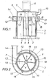
- the device for separating a foam into a liquid and a gas component a cylindrical housing 1, which receives a rotor 2.
- This rotor 2 consists of a circulation cylinder 3, which is supported by means of radial wings 4 on a hub 5, which is driven by an electric motor 6 in the direction of rotation 7.
- the housing 1 forms in the region of one end face of the circulating cylinder 3 a foam inlet 8 and on the opposite end face of the circulating cylinder 3, a gas chamber 9 which is connected to a gas outlet 10.
- the housing 1 In one of the gas chamber 9 facing axial end portion 11 of the circulation cylinder 3 is provided with passage openings 12, which are respectively arranged in the direction of rotation 7 in front of a wing 4, as can be seen in particular in FIG.
- the housing 1 In the region of the axial portion 11, the housing 1 forms a circulating cylinder 3 enclosing, spiral-shaped liquid outlet 13, which merges into a discharge nozzle 14.
- the circulation cylinder 3 In the area of the liquid outlet 13, the circulation cylinder 3 carries circumferentially distributed pump vanes 15, which protrude into the spiral-shaped liquid outlet 13 and form a self-priming pump with this housing.
- the over the foam inlet 8 in the frontally open circulation cylinder 3 penetrating foam is taken from the wings 4 of the rotor 2 and forced centrifugally against the inner wall of the circulation cylinder 3 and during its passage to the through holes 12 in the end portion 11 in a liquid and a gas content separated. While the gas portion leaves the circulation cylinder 3 in the axial direction and flows into the gas chamber 9 of the housing 1, the liquid portion is sucked together with any remaining foam residues through the openings 12 under the action of the pump blades 15 and discharged through the liquid outlet 13 and the drain pipe 14 , depending on the constructive Specifications of the pump formed by the pump 15, a corresponding flow rate can be specified. This also makes it possible to advantageously separate foams of low density into a liquid and a gas fraction, without running the risk of foam residues entering the gas outlet 10.
Landscapes
- Chemical & Material Sciences (AREA)
- Chemical Kinetics & Catalysis (AREA)
- Dispersion Chemistry (AREA)
- Structures Of Non-Positive Displacement Pumps (AREA)
- Degasification And Air Bubble Elimination (AREA)
- Centrifugal Separators (AREA)
- Feeding And Controlling Fuel (AREA)
- Filling Or Discharging Of Gas Storage Vessels (AREA)
- Infusion, Injection, And Reservoir Apparatuses (AREA)
Description
- Die Erfindung bezieht sich auf eine Vorrichtung zum Auftrennen eines Schaums in einen Flüssigkeits- und einen Gasanteil mit einem in einem Gehäuse gelagerten Rotor, der einen mittels radialer Flügel auf einer Nabe abgestützten, auf der einen Stirnseite an einen Schaumeinlauf und auf der gegenüberliegenden Stirnseite an einen Gasabzug des Gehäuses angeschlossenen Umlaufzylinder aufweist, wobei das Gehäuse einen den Umlaufzylinder umschließenden, spiralförmigen Flüssigkeitsablauf bildet, in dessen Bereich der Umlaufzylinder über den Umfang verteilte Durchtrittsöffnungen besitzt.
- Um die Auftrennung des bei einer Essigfermentation anfallenden Schaums in einen Flüssigkeits- und in einen Gasanteil mit einem vergleichsweise geringen Energieeinsatz zu ermöglichen, ist es bekannt (
EP 374 122 B1 - Der Erfindung liegt somit die Aufgabe zugrunde, eine Vorrichtung zum Auftrennen eines Schaums in einen Flüssigkeits- und einen Gasanteil der eingangs geschilderten Art so auszugestalten, daß auch Schäume mit einer vergleichsweise geringen Dichte behandelt werden können, ohne einen Schaumaustritt auf der dem Gasabzug zugekehrten Stirnseite des Umlaufzylinders befürchten zu müssen.
- Die Erfindung löst die gestellte Aufgabe dadurch, daß der Umlaufzylinder im Bereich des Flüssigkeitsablaufes in diesen ragende Pumpenflügel trägt.
- Der Erfindung liegt die Erkenntnis zugrunde, daß bei Schäumen mit einer vergleichsweise geringen Dichte die fliehkraftbedingte Beschleunigung nicht ausreicht, um für eine störungsfreie Weiterförderung der Flüssigkeits- und Schaumanteile außerhalb des Umlaufzylinders zu sorgen. Durch die im Bereich des Flüssigkeitsablaufes erfindungsgemäß vorgesehenen Pumpenflügel auf der Außenwandung des Umlaufzylinders werden einerseits Flüssigkeit und Schaumreste aus dem Umlaufzylinder in den spiralförmigen Flüssigkeitsablauf angesaugt und anderseits auf das angesaugte Gut Druckkräfte im Sinne eines Gutaustrages durch den Flüssigkeitsablauf ausgeübt, so daß selbst bei einem größeren Schaumanfall ein axialer Durchtritt des Schaums zum Gasabzug unterbunden wird. Die im Umlaufzylinder auf den zu behandelnden Schaum einwirkenden Fliehkräfte und die Kraftwirkungen der durch die Pumpenflügel im Bereich des spiralförmigen Flüssigkeitsablaufes erhaltenen, selbstansaugenden Pumpe unterstützen einander in vorteilhafter Weise, so daß auch bei schwierigen Entschäumungsbedingungen eine weitgehende Auftrennung des Schaums in einen Flüssigkeits- und einen Gasanteil sichergestellt wird.
- Um den zu behandelnden Schaum über eine längere Wegstrecke innerhalb des Umlaufzylinders einer entsprechenden Fliehkraftwirkung aussetzen zu können, kann der spiralförmige Flüssigkeitsablauf in einem dem Gasabzug zugekehrten axialen Endabschnitt des Umlaufzylinders vorgesehen sein.
- In der Zeichnung ist der Erfindungsgegenstand beispielsweise dargestellt. Es zeigen
- Fig. 1
- eine erfindungsgemäße Vorrichtung zum Auftrennen eines Schaums in einen Flüssigkeits- und einen Gasanteil in einem schematischen Axialschnitt und
- Fig. 2
- diese Vorrichtung in einem Schnitt nach der Linie II-II der Fig. 1.
- Die Vorrichtung zum Auftrennen eines Schaums in einen Flüssigkeits- und einen Gasanteil weist gemäß dem dargestellten Ausführungsbeispiel ein zylindrisches Gehäuse 1 auf, das einen Rotor 2 aufnimmt. Dieser Rotor 2 besteht aus einem Umlaufzylinder 3, der mit Hilfe radialer Flügel 4 auf einer Nabe 5 abgestützt ist, die durch einen Elektromotor 6 im Umlaufsinn 7 angetrieben wird. Das Gehäuse 1 bildet im Bereich der einen Stirnseite des Umlaufzylinders 3 einen Schaumeinlauf 8 und auf der gegenüberliegenden Stirnseite des Umlaufszylinders 3 eine Gaskammer 9, die an einen Gasabzug 10 angeschlossen ist.
- In einem der Gaskammer 9 zugekehrten axialen Endabschnitt 11 ist der Umlaufzylinder 3 mit Durchtrittsöffnungen 12 versehen, die in Umlaufrichtung 7 jeweils unmittelbar vor einem Flügel 4 angeordnet sind, wie dies insbesondere der Fig. 2 entnommen werden kann. Im Bereich des axialen Abschnittes 11 bildet das Gehäuse 1 einen den Umlaufzylinder 3 umschließenden, spiralförmigen Flüssigkeitsablauf 13, der in einen Ablaufstutzen 14 übergeht. Im Bereich des Flüssigkeitsablaufes 13 trägt der Umlaufzylinder 3 über den Umfang verteilte Pumpenflügel 15, die in den spiralförmigen Flüssigkeitsablauf 13 ragen und mit diesem als Gehäuse eine selbstansaugende Pumpe bilden.
- Der über den Schaumeinlauf 8 in den stirnseitig offenen Umlaufzylinder 3 eindringende Schaum wird von den Flügeln 4 des Rotors 2 mitgenommen und fliehkraftbedingt gegen die Innenwandung des Umlaufzylinders 3 gedrückt und während seines Weges zu den Durchtrittslöchern 12 im Endabschnitt 11 in einen Flüssigkeits- und in einen Gasanteil getrennt. Während der Gasanteil den Umlaufzylinder 3 in axialer Richtung verläßt und in die Gaskammer 9 des Gehäuses 1 strömt, wird der Flüssigkeitsanteil zusammen mit allenfalls noch vorhandenen Schaumresten durch die Durchtrittsöffnungen 12 unter der Einwirkung der Pumpenflügel 15 abgesaugt und durch den Flüssigkeitsablauf 13 und den Ablaufstutzen 14 ausgetragen, wobei in Abhängigkeit von den konstruktiven Vorgaben der mit Hilfe der Pumpenflügel 15 gebildeten Pumpe eine entsprechende Förderleistung vorgegeben werden kann. Damit gelingt es, auch Schäume mit geringer Dichte vorteilhaft in einen Flüssigkeits- und in einen Gasanteil aufzutrennen, ohne Gefahr zu laufen, daß Schaumreste in den Gasabzug 10 gelangen.
Claims (2)
- Vorrichtung zum Auftrennen eines Schaums in einen Flüssigkeits- und einen Gasanteil mit einem in einem Gehäuse (1) gelagerten Rotor (2), der einen mittels radialer Flügel (4) auf einer Nabe (5) abgestützten, auf der einen Stirnseite an einen Schaumeinlauf und auf der gegenüberliegenden Stirnseite an einen Gasabzug (10) des Gehäuses (1) angeschlossenen Umlaufzylinder (3) aufweist, wobei das Gehäuse (1) einen den Umlaufzylinder (3) umschließenden, spiralförmigen Flüssigkeitsablauf (13) bildet, in dessen Bereich der Umlaufzylinder (3) über den Umfang verteilte Durchtrittsöffnungen (12) besitzt, die in Umlaufrichtung (7) jeweils unmittelbar vor einem Flügel (4) angeordnet sind, dadurch gekennzeichnet, daß der Umlaufzylinder (3) im Bereich des Flüssigkeitsablaufes (13) in diesen ragende Pumpenflügel (15) trägt.
- Vorrichtung nach Anspruch 1, dadurch gekennzeichnet, daß der spiralförmige Flüssigkeitsablauf (13) in einem dem Gasabzug (9) zugekehrten axialen Endabschnitt (11) des Umlaufzylinders (3) vorgesehen ist.
Priority Applications (2)
| Application Number | Priority Date | Filing Date | Title |
|---|---|---|---|
| SI200430512T SI1660207T1 (sl) | 2003-09-03 | 2004-08-20 | Naprava za locevanje pene v tekoci in plinasti del |
| PL04764313T PL1660207T3 (pl) | 2003-09-03 | 2004-08-20 | Urządzenie do rozdzielania piany na udział cieczy i gazu |
Applications Claiming Priority (2)
| Application Number | Priority Date | Filing Date | Title |
|---|---|---|---|
| AT0137903A AT412529B (de) | 2003-09-03 | 2003-09-03 | Vorrichtung zum auftrennen eines schaums in einen flüssigkeits- und einen gasanteil |
| PCT/EP2004/009329 WO2005028067A1 (de) | 2003-09-03 | 2004-08-20 | Vorrichtung zum auftrennen eines schaums in einen flüssigkeits- und einen gasanteil |
Publications (2)
| Publication Number | Publication Date |
|---|---|
| EP1660207A1 EP1660207A1 (de) | 2006-05-31 |
| EP1660207B1 true EP1660207B1 (de) | 2007-08-22 |
Family
ID=32932050
Family Applications (1)
| Application Number | Title | Priority Date | Filing Date |
|---|---|---|---|
| EP04764313A Expired - Lifetime EP1660207B1 (de) | 2003-09-03 | 2004-08-20 | Vorrichtung zum auftrennen eines schaums in einen flüssigkeits- und einen gasanteil |
Country Status (9)
| Country | Link |
|---|---|
| EP (1) | EP1660207B1 (de) |
| AT (2) | AT412529B (de) |
| DE (1) | DE502004004759D1 (de) |
| DK (1) | DK1660207T3 (de) |
| ES (1) | ES2293322T3 (de) |
| PL (1) | PL1660207T3 (de) |
| PT (1) | PT1660207E (de) |
| SI (1) | SI1660207T1 (de) |
| WO (1) | WO2005028067A1 (de) |
Cited By (1)
| Publication number | Priority date | Publication date | Assignee | Title |
|---|---|---|---|---|
| DE102020132429A1 (de) | 2020-12-07 | 2022-06-09 | Johannes Daun | Schaumzentrifuge |
Families Citing this family (6)
| Publication number | Priority date | Publication date | Assignee | Title |
|---|---|---|---|---|
| DE102008030531A1 (de) * | 2007-12-17 | 2009-06-18 | Voith Patent Gmbh | Verfahren und Vorrichtung zur Entfernung von Gas, insbesondere Luft aus Flotationsschaum und ihre Verwendung |
| CN106693448A (zh) * | 2015-08-03 | 2017-05-24 | 安徽华明制药有限公司 | 一种乳剂制备过程中的消泡方法 |
| CN112642179B (zh) * | 2020-12-18 | 2022-09-30 | 宁波顺泽橡胶有限公司 | 一种丁腈橡胶生产凝聚破乳消泡装置 |
| US12017157B2 (en) * | 2021-01-22 | 2024-06-25 | Pratt & Whitney Canada Corp. | Deaerator for aircraft engine and associated method of operation |
| US11867357B1 (en) | 2022-09-09 | 2024-01-09 | Pratt & Whitney Canada Corp. | Deaeration conduit |
| US12330089B2 (en) | 2022-09-09 | 2025-06-17 | Pratt & Whitney Canada Corp. | Dynamic deaeration system |
Family Cites Families (4)
| Publication number | Priority date | Publication date | Assignee | Title |
|---|---|---|---|---|
| DE731607C (de) * | 1941-07-15 | 1943-02-11 | Wilhelm Vogelbusch | Schaumzerstoerer |
| SU1043164A1 (ru) * | 1982-02-26 | 1983-09-23 | Московский Ордена Трудового Красного Знамени Институт Химического Машиностроения | Устройство дл пеногашени |
| AT392080B (de) * | 1988-12-13 | 1991-01-25 | Frings & Co Heinrich | Verfahren und vorrichtung zur schaumfuehrung bei einem fermentationsprozess zur essigherstellung |
| DE4009042C2 (de) * | 1990-03-21 | 1996-12-12 | Voith Gmbh J M | Vorrichtung zur Abtrennung von Luft aus Flotationstrüben |
-
2003
- 2003-09-03 AT AT0137903A patent/AT412529B/de not_active IP Right Cessation
-
2004
- 2004-08-20 ES ES04764313T patent/ES2293322T3/es not_active Expired - Lifetime
- 2004-08-20 AT AT04764313T patent/ATE370776T1/de active
- 2004-08-20 WO PCT/EP2004/009329 patent/WO2005028067A1/de not_active Ceased
- 2004-08-20 DK DK04764313T patent/DK1660207T3/da active
- 2004-08-20 DE DE502004004759T patent/DE502004004759D1/de not_active Expired - Lifetime
- 2004-08-20 PT PT04764313T patent/PT1660207E/pt unknown
- 2004-08-20 PL PL04764313T patent/PL1660207T3/pl unknown
- 2004-08-20 EP EP04764313A patent/EP1660207B1/de not_active Expired - Lifetime
- 2004-08-20 SI SI200430512T patent/SI1660207T1/sl unknown
Cited By (2)
| Publication number | Priority date | Publication date | Assignee | Title |
|---|---|---|---|---|
| DE102020132429A1 (de) | 2020-12-07 | 2022-06-09 | Johannes Daun | Schaumzentrifuge |
| DE102020132429B4 (de) * | 2020-12-07 | 2025-09-11 | Johannes Daun | Schaumzentrifuge |
Also Published As
| Publication number | Publication date |
|---|---|
| AT412529B (de) | 2005-04-25 |
| ES2293322T3 (es) | 2008-03-16 |
| SI1660207T1 (sl) | 2008-02-29 |
| ATE370776T1 (de) | 2007-09-15 |
| WO2005028067A1 (de) | 2005-03-31 |
| DK1660207T3 (da) | 2008-01-02 |
| PL1660207T3 (pl) | 2008-01-31 |
| ATA13792003A (de) | 2004-09-15 |
| EP1660207A1 (de) | 2006-05-31 |
| PT1660207E (pt) | 2007-12-03 |
| DE502004004759D1 (de) | 2007-10-04 |
Similar Documents
| Publication | Publication Date | Title |
|---|---|---|
| DE69431204T2 (de) | Blutpumpe | |
| DE4006604C2 (de) | ||
| DE2361328C2 (de) | Zentrifugalpumpe mit Gasabführung aus dem Laufrad | |
| DE1453726A1 (de) | Gasabscheider,insbesondere zur Verwendung mit Tauchpumpen fuer OEl- und Wasserbohrungen | |
| AT412529B (de) | Vorrichtung zum auftrennen eines schaums in einen flüssigkeits- und einen gasanteil | |
| DE3128374A1 (de) | Radialschaufelunterstuetzte seitenkanalpumpe | |
| EP0733805A1 (de) | Faserabweisende Wandflächengestaltung | |
| DE2112762A1 (de) | Seitenkanalpumpe,insbesondere Wirbelpumpe | |
| DE1728419A1 (de) | Fluessigkeitsringverdichter | |
| DE865864C (de) | Zahnradpumpe, insbesondere zur Foerderung von Fluessigkeiten in Flugmotoren | |
| DD277617A1 (de) | Schaelscheibe fuer zentrifugalseparatoren | |
| DE60311165T2 (de) | Kreiselpumpe für niedrige Flussraten mit verbesserter Ansaughöhe | |
| DE1528895C3 (de) | Zentrifugalpumpe | |
| DE10054669C1 (de) | Kreiselpumpe für den Transport grobdisperser Gemische | |
| EP1873399A1 (de) | Kreiselpumpenaggregat | |
| DE731607C (de) | Schaumzerstoerer | |
| EP0036114A1 (de) | Zentrifugal-Saugwascher | |
| DE538987C (de) | Zentrifugalpumpe | |
| DE102020132429B4 (de) | Schaumzentrifuge | |
| DE3341111C2 (de) | Radialkreiselpumpe | |
| WO2019043044A1 (de) | Flüssigkeitsringpumpe | |
| DE3308895C2 (de) | ||
| DE1453719C (de) | Gasabscheider | |
| DE102012104405A1 (de) | Rotationspumpe | |
| DE1115586B (de) | Kanalradpumpe mit an den Aussenseiten der Radwaende zusaetzlich angeordneten Rippen |
Legal Events
| Date | Code | Title | Description |
|---|---|---|---|
| PUAI | Public reference made under article 153(3) epc to a published international application that has entered the european phase |
Free format text: ORIGINAL CODE: 0009012 |
|
| 17P | Request for examination filed |
Effective date: 20051124 |
|
| AK | Designated contracting states |
Kind code of ref document: A1 Designated state(s): AT BE BG CH CY CZ DE DK EE ES FI FR GB GR HU IE IT LI LU MC NL PL PT RO SE SI SK TR |
|
| DAX | Request for extension of the european patent (deleted) | ||
| GRAP | Despatch of communication of intention to grant a patent |
Free format text: ORIGINAL CODE: EPIDOSNIGR1 |
|
| GRAS | Grant fee paid |
Free format text: ORIGINAL CODE: EPIDOSNIGR3 |
|
| GRAA | (expected) grant |
Free format text: ORIGINAL CODE: 0009210 |
|
| AK | Designated contracting states |
Kind code of ref document: B1 Designated state(s): AT BE BG CH CY CZ DE DK EE ES FI FR GB GR HU IE IT LI LU MC NL PL PT RO SE SI SK TR |
|
| REG | Reference to a national code |
Ref country code: GB Ref legal event code: FG4D Free format text: NOT ENGLISH |
|
| REG | Reference to a national code |
Ref country code: CH Ref legal event code: EP |
|
| REG | Reference to a national code |
Ref country code: IE Ref legal event code: FG4D Free format text: LANGUAGE OF EP DOCUMENT: GERMAN |
|
| REF | Corresponds to: |
Ref document number: 502004004759 Country of ref document: DE Date of ref document: 20071004 Kind code of ref document: P |
|
| REG | Reference to a national code |
Ref country code: SE Ref legal event code: TRGR |
|
| REG | Reference to a national code |
Ref country code: PT Ref legal event code: SC4A Free format text: AVAILABILITY OF NATIONAL TRANSLATION Effective date: 20071121 |
|
| GBT | Gb: translation of ep patent filed (gb section 77(6)(a)/1977) |
Effective date: 20071121 |
|
| REG | Reference to a national code |
Ref country code: CH Ref legal event code: NV Representative=s name: E. BLUM & CO. AG PATENT- UND MARKENANWAELTE VSP |
|
| REG | Reference to a national code |
Ref country code: DK Ref legal event code: T3 |
|
| REG | Reference to a national code |
Ref country code: GR Ref legal event code: EP Ref document number: 20070403519 Country of ref document: GR |
|
| PG25 | Lapsed in a contracting state [announced via postgrant information from national office to epo] |
Ref country code: BG Free format text: LAPSE BECAUSE OF FAILURE TO SUBMIT A TRANSLATION OF THE DESCRIPTION OR TO PAY THE FEE WITHIN THE PRESCRIBED TIME-LIMIT Effective date: 20071122 |
|
| REG | Reference to a national code |
Ref country code: PL Ref legal event code: T3 |
|
| REG | Reference to a national code |
Ref country code: EE Ref legal event code: FG4A Ref document number: E001633 Country of ref document: EE Effective date: 20071119 |
|
| REG | Reference to a national code |
Ref country code: ES Ref legal event code: FG2A Ref document number: 2293322 Country of ref document: ES Kind code of ref document: T3 |
|
| ET | Fr: translation filed | ||
| PLBE | No opposition filed within time limit |
Free format text: ORIGINAL CODE: 0009261 |
|
| STAA | Information on the status of an ep patent application or granted ep patent |
Free format text: STATUS: NO OPPOSITION FILED WITHIN TIME LIMIT |
|
| PG25 | Lapsed in a contracting state [announced via postgrant information from national office to epo] |
Ref country code: RO Free format text: LAPSE BECAUSE OF FAILURE TO SUBMIT A TRANSLATION OF THE DESCRIPTION OR TO PAY THE FEE WITHIN THE PRESCRIBED TIME-LIMIT Effective date: 20070822 |
|
| REG | Reference to a national code |
Ref country code: HU Ref legal event code: AG4A Ref document number: E002813 Country of ref document: HU |
|
| 26N | No opposition filed |
Effective date: 20080526 |
|
| PG25 | Lapsed in a contracting state [announced via postgrant information from national office to epo] |
Ref country code: MC Free format text: LAPSE BECAUSE OF NON-PAYMENT OF DUE FEES Effective date: 20080831 |
|
| PG25 | Lapsed in a contracting state [announced via postgrant information from national office to epo] |
Ref country code: CY Free format text: LAPSE BECAUSE OF FAILURE TO SUBMIT A TRANSLATION OF THE DESCRIPTION OR TO PAY THE FEE WITHIN THE PRESCRIBED TIME-LIMIT Effective date: 20070822 |
|
| PGFP | Annual fee paid to national office [announced via postgrant information from national office to epo] |
Ref country code: FI Payment date: 20100712 Year of fee payment: 7 Ref country code: LU Payment date: 20100722 Year of fee payment: 7 |
|
| PG25 | Lapsed in a contracting state [announced via postgrant information from national office to epo] |
Ref country code: FI Free format text: LAPSE BECAUSE OF NON-PAYMENT OF DUE FEES Effective date: 20110820 |
|
| PGFP | Annual fee paid to national office [announced via postgrant information from national office to epo] |
Ref country code: SI Payment date: 20120618 Year of fee payment: 9 |
|
| PGFP | Annual fee paid to national office [announced via postgrant information from national office to epo] |
Ref country code: PT Payment date: 20120220 Year of fee payment: 9 |
|
| PG25 | Lapsed in a contracting state [announced via postgrant information from national office to epo] |
Ref country code: LU Free format text: LAPSE BECAUSE OF NON-PAYMENT OF DUE FEES Effective date: 20110820 |
|
| REG | Reference to a national code |
Ref country code: PT Ref legal event code: MM4A Free format text: LAPSE DUE TO NON-PAYMENT OF FEES Effective date: 20140220 |
|
| REG | Reference to a national code |
Ref country code: SI Ref legal event code: KO00 Effective date: 20140401 |
|
| PG25 | Lapsed in a contracting state [announced via postgrant information from national office to epo] |
Ref country code: SI Free format text: LAPSE BECAUSE OF NON-PAYMENT OF DUE FEES Effective date: 20130821 |
|
| PG25 | Lapsed in a contracting state [announced via postgrant information from national office to epo] |
Ref country code: PT Free format text: LAPSE BECAUSE OF NON-PAYMENT OF DUE FEES Effective date: 20140220 |
|
| PGFP | Annual fee paid to national office [announced via postgrant information from national office to epo] |
Ref country code: EE Payment date: 20140822 Year of fee payment: 11 |
|
| REG | Reference to a national code |
Ref country code: FR Ref legal event code: PLFP Year of fee payment: 12 |
|
| PGFP | Annual fee paid to national office [announced via postgrant information from national office to epo] |
Ref country code: GR Payment date: 20150827 Year of fee payment: 12 |
|
| REG | Reference to a national code |
Ref country code: EE Ref legal event code: MM4A Ref document number: E001633 Country of ref document: EE Effective date: 20150831 |
|
| PG25 | Lapsed in a contracting state [announced via postgrant information from national office to epo] |
Ref country code: EE Free format text: LAPSE BECAUSE OF NON-PAYMENT OF DUE FEES Effective date: 20150831 |
|
| REG | Reference to a national code |
Ref country code: FR Ref legal event code: PLFP Year of fee payment: 13 |
|
| PG25 | Lapsed in a contracting state [announced via postgrant information from national office to epo] |
Ref country code: GR Free format text: LAPSE BECAUSE OF NON-PAYMENT OF DUE FEES Effective date: 20170309 |
|
| REG | Reference to a national code |
Ref country code: GR Ref legal event code: ML Ref document number: 20070403519 Country of ref document: GR Effective date: 20170309 |
|
| REG | Reference to a national code |
Ref country code: FR Ref legal event code: PLFP Year of fee payment: 14 |
|
| PGFP | Annual fee paid to national office [announced via postgrant information from national office to epo] |
Ref country code: CZ Payment date: 20170821 Year of fee payment: 14 Ref country code: GB Payment date: 20170830 Year of fee payment: 14 Ref country code: IT Payment date: 20170825 Year of fee payment: 14 Ref country code: ES Payment date: 20170926 Year of fee payment: 14 |
|
| PGFP | Annual fee paid to national office [announced via postgrant information from national office to epo] |
Ref country code: HU Payment date: 20170920 Year of fee payment: 14 Ref country code: IE Payment date: 20170829 Year of fee payment: 14 Ref country code: SE Payment date: 20170828 Year of fee payment: 14 Ref country code: TR Payment date: 20170802 Year of fee payment: 14 |
|
| REG | Reference to a national code |
Ref country code: FR Ref legal event code: PLFP Year of fee payment: 15 |
|
| PGFP | Annual fee paid to national office [announced via postgrant information from national office to epo] |
Ref country code: PL Payment date: 20170818 Year of fee payment: 14 |
|
| PGFP | Annual fee paid to national office [announced via postgrant information from national office to epo] |
Ref country code: FR Payment date: 20180830 Year of fee payment: 15 Ref country code: NL Payment date: 20180824 Year of fee payment: 15 |
|
| PGFP | Annual fee paid to national office [announced via postgrant information from national office to epo] |
Ref country code: AT Payment date: 20180820 Year of fee payment: 15 Ref country code: BE Payment date: 20180824 Year of fee payment: 15 Ref country code: CH Payment date: 20180824 Year of fee payment: 15 Ref country code: DK Payment date: 20180824 Year of fee payment: 15 |
|
| REG | Reference to a national code |
Ref country code: SE Ref legal event code: EUG |
|
| GBPC | Gb: european patent ceased through non-payment of renewal fee |
Effective date: 20180820 |
|
| PG25 | Lapsed in a contracting state [announced via postgrant information from national office to epo] |
Ref country code: CZ Free format text: LAPSE BECAUSE OF NON-PAYMENT OF DUE FEES Effective date: 20180820 Ref country code: HU Free format text: LAPSE BECAUSE OF NON-PAYMENT OF DUE FEES Effective date: 20180821 |
|
| REG | Reference to a national code |
Ref country code: SK Ref legal event code: MM4A Ref document number: E 2632 Country of ref document: SK Effective date: 20180820 |
|
| REG | Reference to a national code |
Ref country code: IE Ref legal event code: MM4A |
|
| PG25 | Lapsed in a contracting state [announced via postgrant information from national office to epo] |
Ref country code: SK Free format text: LAPSE BECAUSE OF NON-PAYMENT OF DUE FEES Effective date: 20180820 Ref country code: SE Free format text: LAPSE BECAUSE OF NON-PAYMENT OF DUE FEES Effective date: 20180821 |
|
| PG25 | Lapsed in a contracting state [announced via postgrant information from national office to epo] |
Ref country code: IT Free format text: LAPSE BECAUSE OF NON-PAYMENT OF DUE FEES Effective date: 20180820 Ref country code: IE Free format text: LAPSE BECAUSE OF NON-PAYMENT OF DUE FEES Effective date: 20180820 |
|
| REG | Reference to a national code |
Ref country code: ES Ref legal event code: FD2A Effective date: 20190918 |
|
| PG25 | Lapsed in a contracting state [announced via postgrant information from national office to epo] |
Ref country code: GB Free format text: LAPSE BECAUSE OF NON-PAYMENT OF DUE FEES Effective date: 20180820 Ref country code: ES Free format text: LAPSE BECAUSE OF NON-PAYMENT OF DUE FEES Effective date: 20180821 |
|
| PG25 | Lapsed in a contracting state [announced via postgrant information from national office to epo] |
Ref country code: PL Free format text: LAPSE BECAUSE OF NON-PAYMENT OF DUE FEES Effective date: 20180820 |
|
| REG | Reference to a national code |
Ref country code: DK Ref legal event code: EBP Effective date: 20190831 |
|
| REG | Reference to a national code |
Ref country code: NL Ref legal event code: MM Effective date: 20190901 |
|
| REG | Reference to a national code |
Ref country code: AT Ref legal event code: MM01 Ref document number: 370776 Country of ref document: AT Kind code of ref document: T Effective date: 20190820 |
|
| PG25 | Lapsed in a contracting state [announced via postgrant information from national office to epo] |
Ref country code: AT Free format text: LAPSE BECAUSE OF NON-PAYMENT OF DUE FEES Effective date: 20190820 |
|
| PG25 | Lapsed in a contracting state [announced via postgrant information from national office to epo] |
Ref country code: LI Free format text: LAPSE BECAUSE OF NON-PAYMENT OF DUE FEES Effective date: 20190831 Ref country code: CH Free format text: LAPSE BECAUSE OF NON-PAYMENT OF DUE FEES Effective date: 20190831 |
|
| REG | Reference to a national code |
Ref country code: BE Ref legal event code: MM Effective date: 20190831 |
|
| PG25 | Lapsed in a contracting state [announced via postgrant information from national office to epo] |
Ref country code: FR Free format text: LAPSE BECAUSE OF NON-PAYMENT OF DUE FEES Effective date: 20190831 Ref country code: DK Free format text: LAPSE BECAUSE OF NON-PAYMENT OF DUE FEES Effective date: 20190831 Ref country code: NL Free format text: LAPSE BECAUSE OF NON-PAYMENT OF DUE FEES Effective date: 20190901 |
|
| PG25 | Lapsed in a contracting state [announced via postgrant information from national office to epo] |
Ref country code: BE Free format text: LAPSE BECAUSE OF NON-PAYMENT OF DUE FEES Effective date: 20190831 |
|
| PG25 | Lapsed in a contracting state [announced via postgrant information from national office to epo] |
Ref country code: TR Free format text: LAPSE BECAUSE OF NON-PAYMENT OF DUE FEES Effective date: 20180820 |
|
| P01 | Opt-out of the competence of the unified patent court (upc) registered |
Effective date: 20230607 |
|
| PGFP | Annual fee paid to national office [announced via postgrant information from national office to epo] |
Ref country code: DE Payment date: 20230828 Year of fee payment: 20 |
|
| REG | Reference to a national code |
Ref country code: DE Ref legal event code: R071 Ref document number: 502004004759 Country of ref document: DE |