EP1661736A2 - Dispositif de valve - Google Patents
Dispositif de valve Download PDFInfo
- Publication number
- EP1661736A2 EP1661736A2 EP05003885A EP05003885A EP1661736A2 EP 1661736 A2 EP1661736 A2 EP 1661736A2 EP 05003885 A EP05003885 A EP 05003885A EP 05003885 A EP05003885 A EP 05003885A EP 1661736 A2 EP1661736 A2 EP 1661736A2
- Authority
- EP
- European Patent Office
- Prior art keywords
- elastic member
- valve
- valve stem
- opening
- valve device
- Prior art date
- Legal status (The legal status is an assumption and is not a legal conclusion. Google has not performed a legal analysis and makes no representation as to the accuracy of the status listed.)
- Withdrawn
Links
- 230000005540 biological transmission Effects 0.000 claims abstract description 10
- 239000007787 solid Substances 0.000 claims description 5
- 230000005611 electricity Effects 0.000 claims 2
- 239000000463 material Substances 0.000 description 9
- 239000011347 resin Substances 0.000 description 6
- 229920005989 resin Polymers 0.000 description 6
- 238000012544 monitoring process Methods 0.000 description 3
- 238000004382 potting Methods 0.000 description 3
- 239000002184 metal Substances 0.000 description 2
- 238000001514 detection method Methods 0.000 description 1
- 230000004048 modification Effects 0.000 description 1
- 238000012986 modification Methods 0.000 description 1
- 238000000465 moulding Methods 0.000 description 1
- -1 preferably Substances 0.000 description 1
- 230000000087 stabilizing effect Effects 0.000 description 1
Images



Classifications
-
- B—PERFORMING OPERATIONS; TRANSPORTING
- B60—VEHICLES IN GENERAL
- B60C—VEHICLE TYRES; TYRE INFLATION; TYRE CHANGING; CONNECTING VALVES TO INFLATABLE ELASTIC BODIES IN GENERAL; DEVICES OR ARRANGEMENTS RELATED TO TYRES
- B60C23/00—Devices for measuring, signalling, controlling, or distributing tyre pressure or temperature, specially adapted for mounting on vehicles; Arrangement of tyre inflating devices on vehicles, e.g. of pumps or of tanks; Tyre cooling arrangements
- B60C23/02—Signalling devices actuated by tyre pressure
- B60C23/04—Signalling devices actuated by tyre pressure mounted on the wheel or tyre
- B60C23/0491—Constructional details of means for attaching the control device
- B60C23/0494—Valve stem attachments positioned inside the tyre chamber
-
- B—PERFORMING OPERATIONS; TRANSPORTING
- B60—VEHICLES IN GENERAL
- B60C—VEHICLE TYRES; TYRE INFLATION; TYRE CHANGING; CONNECTING VALVES TO INFLATABLE ELASTIC BODIES IN GENERAL; DEVICES OR ARRANGEMENTS RELATED TO TYRES
- B60C23/00—Devices for measuring, signalling, controlling, or distributing tyre pressure or temperature, specially adapted for mounting on vehicles; Arrangement of tyre inflating devices on vehicles, e.g. of pumps or of tanks; Tyre cooling arrangements
- B60C23/02—Signalling devices actuated by tyre pressure
- B60C23/04—Signalling devices actuated by tyre pressure mounted on the wheel or tyre
- B60C23/0408—Signalling devices actuated by tyre pressure mounted on the wheel or tyre transmitting the signals by non-mechanical means from the wheel or tyre to a vehicle body mounted receiver
-
- F—MECHANICAL ENGINEERING; LIGHTING; HEATING; WEAPONS; BLASTING
- F16—ENGINEERING ELEMENTS AND UNITS; GENERAL MEASURES FOR PRODUCING AND MAINTAINING EFFECTIVE FUNCTIONING OF MACHINES OR INSTALLATIONS; THERMAL INSULATION IN GENERAL
- F16K—VALVES; TAPS; COCKS; ACTUATING-FLOATS; DEVICES FOR VENTING OR AERATING
- F16K15/00—Check valves
- F16K15/20—Check valves specially designed for inflatable bodies, e.g. tyres
Definitions
- the present invention relates to a valve attachable to a wheel of a vehicle, and more particularly, to a valve functioning as a transmitter for a tire condition monitoring system.
- a wireless type tire condition monitoring system has been proposed for monitoring from the passenger compartment, the condition of a tire attached to a vehicle.
- the system includes a transmitter installed in the interior of the tire and a receiver.
- the transmitter detects the condition of the tire such as the pneumatic pressure and temperature within the tire.
- the transmitter transmits information regarding the tire condition to the receiver and the receiver displays the information on a display provided in the passenger compartment, when necessary.
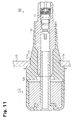
- Fig. 11 shows a transmitter described in U.S. Patent No. 6,005,480.
- the transmitter is configured as a snap-in valve device including a transmitter unit 112 and a valve unit 100 connected to the transmitter unit 112.
- the valve unit 100 includes a stem 116 connected to the transmitter unit 112, a valve body 117 incorporated in the stem 116 for supplying air to the interior of the tire, and an elastic member 111 encompassing the stem 116.
- the transmitter unit 112 is received in the interior of the tire, which is defined by the tire (not shown) and a vehicle wheel 115. For attaching the valve unit 100 to the wheel 115, the valve unit 100 is inserted into an opening 115a defined in the wheel 115.
- the valve unit 100 is then pressed toward the exterior of the wheel 115 until an annular engaging portion 111a of the elastic member 111 is fully exposed from the opening 111a. Since the annular engaging portion 111a has a diameter larger than that of the opening 115a, the engaging portion 111a is deformed in a compressed manner while it is passed through the opening 115a. The engaging portion 111a is released from pressing force when fully released from the opening 115a, such that the engaging portion 111a is enlarged radially outward. The valve unit 100 is thus prevented from falling from the opening 115a.
- the stem 116 extending through the valve unit 100 must be formed of hard material such as metal.
- the transmitter unit 112 is thus secured to the stem 116, which is relatively hard.
- the stem 116 is formed of the hard material, compressive deformation of the elastic member 111 encompassing the stem 116 is hampered. It is thus necessary to increase the force for pressing the annular engaging portion 111a into the opening 115a for deforming the engaging portion 111a radially inward as compressed. This makes it difficult to attach the valve unit 100 to the wheel 115.
- a space 120 is defined between the transmitter 112 and the elastic member 111 for facilitating the compressive deformation of the elastic member 111.
- the valve unit 110 When the valve unit 110 is inserted into the opening 115a of the wheel 115, a portion of the elastic member 111 is deformed and thus received in the space 120.
- the space 120 is relatively spaced from the annular engaging portion 111 that is deformed in a compressed manner when passing through the opening 115a. Accordingly, the attachment of the valve unit 100 to the wheel 115 still requires relatively great force.
- the elastic member 111 is formed of rubber and thus deteriorates relatively quickly. However, since the elastic member 111 of the aforementioned device is fixed to the stem 116 in an inseparable manner, at least the entire portion of the valve unit 100 must be replaced when the elastic member 111 is deteriorated, and the cost for replacement is increased.
- the invention provides a valve device attachable to a wheel including a tire in a state where the valve device penetrates through an opening of the wheel.
- the valve device comprises a transmitter unit for detecting a condition of the tire and generating a transmission signal which indicates the detected condition of the tire, a valve stem extending from the transmitter unit and an elastic member disposed to surround the valve stem.
- the elastic member has an annular attaching portion that has a diameter greater than the diameter of the opening.
- the valve stem is attached to the wheel in a state where the attaching portion is attached to a portion of the wheel around the opening by passing the attaching portion through the opening by compressibly deforming the attaching portion.
- the attaching portion includes a recessed portion for facilitating compressibly deforming the attaching portion.
- Fig. 1 shows a snap-in valve device 10 in a state attached to a wheel 15 of a vehicle.
- Fig. 2 is a cross-sectional view showing the snap-in valve device 10.
- the snap-in valve device 10 includes a valve unit 19 and a transmitter unit 12.
- the valve unit 19 has a hollow cylindrical valve stem 16 extending from the transmitter unit 12.
- a valve body 17 is incorporated in a distal end of the valve stem 16 such that the valve body 17 is accommodated in an air introduction hole 16a of the valve stem 16.
- air introduction hole 16a of the valve stem 16 Through the valve body 17 and the air introduction hole 16a, air is supplied to the interior of a tire (not shown) attached to the wheel 15.
- the distal end of the valve stem 16 is covered and protected by a cap 14.
- the valve stem 16 configures the main structure for the valve unit 19 and is formed of relatively hard material such as metal.
- a hollow and cylindrical elastic member 11 encompasses the valve stem 16.
- the elastic member 11 is formed of an elastically deformable material, preferably, rubber.
- the elastic member 11 is fitted into an opening 15a defined in the wheel 15 as deformed in a compressed manner, such that the valve unit 19 is secured to the wheel 15.
- the transmitter unit 12 includes a resin casing 30 connected to the valve stem 16 and a transmitter module 13 received in the casing 30 in a removable manner. Since the snap-in valve device 10 must be secured to the wheel 15 stably, the transmitter unit 12 must be connected securely to the valve unit 19, which is directly engaged with the wheel 15. It is therefore desirable that the valve stem 16 be of hard material, or that the main structure of the valve unit be formed integrally with the resin casing 30 of the transmitter unit 12. In this case, it is preferable that the casing 30 be molded with the proximal end of the valve stem 16 placed in a mold, through so-called insert molding. A connecting flange 25 is formed at the proximal end of the valve stem 16.
- the connecting flange 25 is embedded in the casing 30 and thus improves the connection strength between the valve stem 16 and the casing 30.
- the transmitter unit 12 and the valve unit 19 may be fabricated separately. The transmitter unit 12 and the valve unit 19 are then connected to each other in a separable or inseparable manner.
- the elastic member 11 includes a base 22, a groove-like annular attaching portion 23, and an annular engaging portion 20, which are arranged in this order from the proximal end to the distal end of the elastic member 11.
- the snap-in valve device 10 is attached to the wheel 15 in a state in which the attaching portion 23 is fitted into the opening 15a and an area of the wheel 15 around the opening 15a is supported by the base 22 and the engaging portion 20.
- the diameter of the attaching portion 23 is larger than that of the opening 15a. Therefore, with the snap-in valve device 10 attached to the wheel 15, the attaching portion 23 receives pressing force acting radially inward from the inner circumferential wall of the opening 15a.
- the annular engaging portion 20 is shaped in a tapered manner toward the distal end of the elastic member 11.
- the maximum diameter of the engaging portion 20 (the outer diameter of the section of the engaging portion 20 adjacent to the annular attaching portion 23) is larger than the diameter of the opening 15a.
- the engaging portion 20 When the engaging portion 20 is fully exposed from the opening 15a, the engaging portion 20 is released from the pressing force of the inner circumferential wall of the opening 15a. The engaging portion 20 is thus enlarged radially outward, such that the engaging portion 20 is engaged with the portion of the wheel 15 corresponding to the opening 15a. Accordingly, the valve unit 19 is prevented from falling from the opening 15a.
- the diameter of the annular engaging portion 20 (particularly, the diameter of the section of the engaging portion 20 adjacent to the attaching portion 23) be enlarged to the possible maximum margin with respect to that of the opening 15a.
- the diameter of the engaging portion 20 is excessively large as compared to that of the opening 15a, the compressive deformation of the engaging portion 20, which allows the engaging portion 20 to pass through the opening 15a, is hampered when the snap-in valve device 10 is attached to the wheel 15.
- the valve stem 16 located radially inward from the elastic member 11 has relatively high rigidity, the valve stem 16 hampers the compressive deformation of the annular engaging portion 20.
- a plurality of recessed portions, or grooves 21, are defined in the surface of the engaging portion 20.
- the grooves 21 extend along the axis of the elastic member 11 as spaced at equal angular intervals about the axis of the elastic member 11. If compressive force is applied to the annular engaging portion 20 in a radial inward direction, the annular engaging portion 20 is deformed such that the deformed portion is received by the spaces defined by the grooves 21. This facilitates the compressive deformation of the engaging portion 20, as compared to the case in which the grooves 21 are not provided. It is thus easy to pass the annular engaging portion 20 through the opening 15a.
- each of the grooves 21 has a V-shaped cross section.
- the proportion of the total cross-sectional area of the grooves 21 to the cross-sectional area of the solid portion of the elastic member 11 corresponding to the engaging portion 20 is preferably not less than 5 percent but not more than 15 percent.
- the proportion represented by the equation (B x n)/A x 100 is not less than 5 percent but not more than 15 percent. If such proportion is less than 5 percent, passing of the annular engaging portion 20 through the opening 15a is not sufficiently facilitated. In contrast, if the proportion exceeds 15 percent, the rigidity of the engaging portion 20 becomes excessively low. In this case, the elastic member 11 is easily separated from the opening 15a. That is, the aforementioned range of proportion, 5 to 15 percent, is preferred for easily fitting the valve unit 19 into the opening 15a and then preventing the valve unit 19 from the opening 15a.
- the recessed portions for facilitating the compressive deformation of the engaging portion 20 are not restricted to the grooves 21.
- the recessed portions may be shaped and arranged in any other suitable manner, as long as the solid portion of the annular engaging portion 20 is reduced.
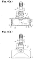
- the cross-sectional shape of each groove 21 may be rectangular, as shown in Fig. 6(b), rather than the V-shape.
- each groove 21 may have a U-shaped cross section.
- the dimensions (the axial dimension, the lateral dimension, and the depth) of each groove 21, the extending direction of the groove 21, and the number of the grooves 21 may be modified as needed.
- a plurality of recesses 28 each having an arched cross-sectional shape may be defined in the surface of the annular engaging portion 20, instead of the grooves 21.
- the elastic member 11 is attached to the valve stem 16 in a separable manner, referring to Fig. 5. Although the elastic member 11 is exposed to the external environment, the elastic member 11 is formed of a material that is relatively easily deteriorated, such as rubber. The life of the elastic member 11 is thus relatively short, as compared to the remaining components of the snap-in valve device 10. If the elastic member 11 is inseparable from the valve stem 16, the snap-in valve device 10 as a whole must be replaced every time the elastic member 11 becomes unusable. This increases replacement cost for the snap-in valve device 10. However, if the elastic member 11 is attached to the valve stem 16 in a separable manner, as in the illustrated embodiment, the elastic member 11 is replaceable independently from the remainder of the device 10. The cost for the snap-in valve device 10 is thus saved.
- the valve stem 16 includes a first holding flange 26 with a relatively large diameter and a second holding flange 27 with a relatively small diameter.
- the first holding flange 26 is formed near the proximal end of the valve stem 16.
- the second holding flange 27 is spaced from the first holding flange 26 in the axial direction of the valve stem 16 toward the distal end of the valve stem 16.
- the second holding flange 27 is shaped in a tapered manner toward the distal end of the valve stem 16.
- the maximum outer diameter of the second holding flange 27 is larger than the inner diameter of the elastic member 11.
- the elastic member 11 is held by the first and second holding flanges 26, 27 with respect to the axial direction of the elastic member 11.
- the valve stem 16 For attaching the elastic member 11 to the valve stem 16, the valve stem 16, with the cap 14 removed from the valve stem 16, is inserted into the elastic member 11 from the distal end of the valve stem 16. When reaching a position beyond the second holding flange 27, the elastic member 11 is held between the first holding flange 26 and the second holding flange 27.
- the tapered shape of the second holding flange 27 makes it easy for the elastic member 11 to proceed along and beyond the second holding flange 27.
- the valve stem 16 includes an annular recess 18 defined in a portion between the first and second holding flanges 26, 27, or a portion of the valve stem 16 to which the elastic member 11 is attached.
- the annular recess 18 corresponds to a potion of the valve stem 16 between the first and second holding flanges 26, 27 having a reduced diameter, as compared to the remainder of the valve stem 16.
- the annular recess 18 is located at an axial position corresponding to the opening 15a with the valve stem 16 attached to the wheel 15.
- the annular recess 18 is located at a position offset from the annular engaging portion 20 with respect to the axial direction of the elastic member 11.
- the annular attaching portion 23 which diameter is larger than that of the opening 15a, is pressed by the inner circumferential wall of the opening 15a with the snap-in valve device 10 attached to the wheel 15.
- a portion of the elastic member 11 is deformed and thus received by the space defined by the annular recess 18, as shown in Fig. 3, such that the deformed portion is engaged with the annular recess 18. Therefore, regardless of that the elastic member 11 is separable from the valve stem 16, the elastic member 11 is fixed to the valve stem 16 securely and stably, while restricted from axial movement with respect to the valve stem 16.
- the snap-in valve device 10 is configured such that the transmitter module 13 is separable from the casing 20, as illustrated in Fig. 8.
- the transmitter module 13 includes a resin case 35 having a square box-like shape and a circuit unit 36, which is accommodated in the case 35.
- the circuit unit 36 includes a circuit board 37 and a plurality of electronic elements formed on the circuit board 37, a controller 38, a pressure sensor 39, and a transmission circuit 40, each of which is formed as a chip.
- a battery 41 is provided on the circuit board 37 for supplying power to the electronic elements on the circuit board 37.
- the pressure sensor 39 serving as a tire condition sensor, detects the pneumatic pressure in the interior of the tire and provides the controller 38 with pneumatic pressure data obtained from the detection.
- the controller 38 sends data including the pneumatic pressure data to the transmission circuit 40.
- the transmission circuit 40 generates a transmission signal from the received data and transmits the signal wirelessly through a transmission antenna (not shown).
- the resin case 35 is filled with potting material such that the circuit unit 36 in the case 35 is covered by the potting material except for a pressure sensing surface of the pressure sensor 39.
- the resin case 35 has a downward opening. The potting material is thus filled in the case 35 with the circuit unit 36 accommodated in the case 35 from the downward opening of the case 35.
- an engagement mechanism is deployed between the casing 30 and the transmitter module 13 for engaging the casing 30 and the transmitter module 13 with each other in a separable manner.
- the casing 30 has an accommodating portion 31 having an opening facing the opposite direction with respect to the valve unit 19.
- the transmitter module 13 is selectively inserted into or removed from the opening of the accommodating portion 31.
- a pair of engaging pieces 32 are formed at opposing sides of the casing 30 near the opening of the accommodating portion 31, a pair of engaging pieces 32 are formed.
- a pair of receiving members 33 each having a square flame-like shape are formed at opposed sides of the resin case 35 of the transmitter module 13.
- the transmitter module 13 For installing the transmitter module 13 in the casing 30, the transmitter module 13 is inserted into the accommodating portion 31 of the casing 30, such that each of the engaging pieces 32 is passed through the corresponding one of the receiving members 33. At this stage, each engaging piece 32 is elastically deformed in an inward direction by the corresponding receiving member 33. When the transmitter module 13 is fully received in the accommodating portion 31, each engaging piece 32 restores the original shape and is thus engaged with the corresponding receiving member 33. In contrast, for separating the transmitter module 13 from the casing 30, each of the engaging pieces 32 is elastically deformed in the inward direction such that the engaging piece 32 is released from the engagement with the corresponding receiving member 33. The transmitter module 13 is then removed from the accommodating portion 31.
- the engagement mechanism between the casing 30 and the transmitter module 13 is not restricted to the illustrated structure but may be modified as needed.
- the opening of the accommodating portion 31 of the casing 30 is oriented parallel with the rotational axis of the wheel 15.
- This structure reduces the force acting parallel with the rotational axis of the wheel 15 when the vehicle is moving.
- the transmitter module 13 is thus prevented from falling from the casing 30.
- the snap-in valve 10 is subjected to centrifugal force produced by rotation of the wheel 15, the transmitter module 13 is supported by an upper wall of the casing 30.
- the transmitter module 13 is supported by opposing side walls of the casing 30. Accordingly, in the illustrated embodiment, in which the transmitter module 13 is removable from the snap-in valve device 10, the parallel orientation of the opening of the accommodating portion 31 with the rotational axis of the wheel 15 is effective in preventing the transmitter module 13 from falling therefrom.
Landscapes
- Engineering & Computer Science (AREA)
- Mechanical Engineering (AREA)
- General Engineering & Computer Science (AREA)
- Check Valves (AREA)
- Measuring Fluid Pressure (AREA)
- Safety Valves (AREA)
- Indication Of The Valve Opening Or Closing Status (AREA)
Applications Claiming Priority (1)
| Application Number | Priority Date | Filing Date | Title |
|---|---|---|---|
| JP2004347485A JP2006151295A (ja) | 2004-11-30 | 2004-11-30 | スナップインバルブ装置 |
Publications (2)
| Publication Number | Publication Date |
|---|---|
| EP1661736A2 true EP1661736A2 (fr) | 2006-05-31 |
| EP1661736A3 EP1661736A3 (fr) | 2006-06-07 |
Family
ID=35519826
Family Applications (1)
| Application Number | Title | Priority Date | Filing Date |
|---|---|---|---|
| EP05003885A Withdrawn EP1661736A3 (fr) | 2004-11-30 | 2005-02-23 | Dispositif de valve |
Country Status (4)
| Country | Link |
|---|---|
| US (1) | US20060125612A1 (fr) |
| EP (1) | EP1661736A3 (fr) |
| JP (1) | JP2006151295A (fr) |
| CN (1) | CN1781745A (fr) |
Cited By (7)
| Publication number | Priority date | Publication date | Assignee | Title |
|---|---|---|---|---|
| WO2008091973A3 (fr) * | 2007-01-24 | 2008-11-20 | Continental Automotive Gmbh | Capteur de surveillance de la pression des pneus et procédé de montage |
| GB2526893A (en) * | 2014-06-06 | 2015-12-09 | E Lead Electronic Co Ltd | Reinforced tire valve of tire pressure detecting device |
| CN105313609A (zh) * | 2014-08-01 | 2016-02-10 | 张泽婵 | 一种新型的可换电池胎压检测装置 |
| FR3048156A1 (fr) * | 2016-02-23 | 2017-08-25 | Continental Automotive France | Boitier de module electronique et unite electronique de mesure de parametres de fonctionnement d'une roue de vehicule |
| WO2019122624A1 (fr) * | 2017-12-21 | 2019-06-27 | Continental Automotive France | Valve de gonflage pour jante de pneumatique avec limitation de déformation élastique |
| GB2607263A (en) * | 2021-03-23 | 2022-12-07 | Continental Automotive Gmbh | TPMS with flexible shape valve system |
| FR3148542A1 (fr) * | 2023-05-11 | 2024-11-15 | Continental Automotive Technologies GmbH | Capteur de mesure pour roue de véhicule automobile |
Families Citing this family (27)
| Publication number | Priority date | Publication date | Assignee | Title |
|---|---|---|---|---|
| JP4522953B2 (ja) * | 2005-06-22 | 2010-08-11 | 太平洋工業株式会社 | タイヤバルブユニット |
| JP2009253313A (ja) | 2008-04-01 | 2009-10-29 | Panasonic Corp | プラズマディスプレイ装置 |
| US8047068B2 (en) * | 2008-08-01 | 2011-11-01 | Schrader Electronics, Inc. | Snap-in tire valve |
| WO2010054567A1 (fr) * | 2008-11-17 | 2010-05-20 | 杭州万通气门嘴有限公司 | Valve de chambre à air montée sur une boîte électronique d’un système de surveillance de la pression des pneus pour automobile |
| CN101474949B (zh) | 2008-11-17 | 2010-12-29 | 杭州万通气门嘴有限公司 | 一种汽车轮胎气门嘴 |
| JP5546808B2 (ja) * | 2009-07-03 | 2014-07-09 | 日立マクセル株式会社 | 扁平形電池の取付方法及び回転部分に取り付けられる装置 |
| FR2954733B1 (fr) * | 2009-12-28 | 2012-03-02 | Continental Automotive France | Unite electronique de mesure de parametres de fonctionnement d'une roue de vehicule,comprenant un boitier electronique et une valve de gonflage |
| FR2978378B1 (fr) * | 2011-07-28 | 2013-09-06 | Continental Automotive France | Unite electronique de mesure de parametres de fonctionnement d'une roue de vehicule, comprenant un boitier electronique et une valve de gonflage |
| US8474312B2 (en) * | 2011-12-02 | 2013-07-02 | Josn Electronic Co., Ltd. | Tire pressure monitor |
| WO2013132969A1 (fr) * | 2012-03-08 | 2013-09-12 | 日産自動車株式会社 | Dispositif de contrôle de pression d'air de pneu |
| JP5741764B2 (ja) * | 2012-03-08 | 2015-07-01 | 日産自動車株式会社 | タイヤ空気圧モニター装置 |
| WO2013132968A1 (fr) * | 2012-03-08 | 2013-09-12 | 日産自動車株式会社 | Dispositif de contrôle de pression d'air de pneu |
| WO2013133307A1 (fr) * | 2012-03-08 | 2013-09-12 | 日産自動車株式会社 | Dispositif de contrôle de pression d'air de pneu |
| JP5896014B2 (ja) * | 2012-03-09 | 2016-03-30 | 日産自動車株式会社 | タイヤ空気圧モニター装置 |
| JP5741768B2 (ja) * | 2012-03-09 | 2015-07-01 | 日産自動車株式会社 | タイヤ空気圧モニター装置 |
| DE102012105249A1 (de) * | 2012-06-15 | 2013-12-19 | Orange Electronic Co., Ltd. | Ventilschaft für einen drahtlosen Reifendruckdetektor |
| JP2014008935A (ja) * | 2012-07-02 | 2014-01-20 | Orange Electronic Co Ltd | 無線タイヤ圧検出器のバルブステム |
| JP2014073843A (ja) * | 2014-01-27 | 2014-04-24 | Pacific Ind Co Ltd | スナップインバルブ及びタイヤバルブユニット |
| CN105090572A (zh) * | 2014-05-14 | 2015-11-25 | 怡利电子工业股份有限公司 | 强化弹性气嘴 |
| DE102014113573A1 (de) * | 2014-09-19 | 2016-03-24 | Huf Hülsbeck & Fürst Gmbh & Co. Kg | Reifendruckkontrollsystem für ein Fahrzeug |
| CN104325847A (zh) * | 2014-10-28 | 2015-02-04 | 芜湖赛德交通设备有限公司 | 一种可循环使用的胎压监测装置 |
| JP6333205B2 (ja) * | 2015-03-23 | 2018-05-30 | 太平洋工業株式会社 | タイヤバルブ |
| KR101897889B1 (ko) * | 2016-02-03 | 2018-09-12 | 다이헤요 고교 가부시키가이샤 | 타이어 밸브 유닛 |
| JP6281715B2 (ja) * | 2016-02-24 | 2018-02-21 | トヨタ自動車株式会社 | スナップインバルブの交換要否判定装置 |
| CN109203872B (zh) * | 2017-07-06 | 2025-01-24 | 深圳市道通科技股份有限公司 | 一种胎压传感器 |
| US11007827B2 (en) * | 2018-06-27 | 2021-05-18 | Ford Global Technologies, Llc | Tire-pressure-monitoring system |
| US11385117B2 (en) * | 2020-01-31 | 2022-07-12 | Sensata Technologies, Inc. | Tire pressure monitoring module with thru-valve construction |
Family Cites Families (8)
| Publication number | Priority date | Publication date | Assignee | Title |
|---|---|---|---|---|
| US3422836A (en) * | 1966-06-20 | 1969-01-21 | Goodyear Tire & Rubber | Valve for dual chambered tires |
| US3542109A (en) * | 1968-06-27 | 1970-11-24 | Scovill Manufacturing Co | Snap-in tire valve |
| FR2385548A1 (fr) * | 1977-03-30 | 1978-10-27 | Michelin & Cie | Valve pour pneumatique |
| US6005480A (en) * | 1998-05-20 | 1999-12-21 | Schrader-Bridgeport International, Inc. | Tire valve and associated tire pressure sending unit |
| JP3898573B2 (ja) * | 2001-06-28 | 2007-03-28 | 太平洋工業株式会社 | タイヤ状態監視装置の送信機及びその製造方法 |
| DE10236140A1 (de) * | 2002-08-07 | 2004-02-19 | Schefenacker Vision Systems Germany Gmbh & Co. Kg | Vorrichtung zum Messen des Druckes und/oder der Lufttemperatur eines Reifens |
| US6722409B1 (en) * | 2002-11-04 | 2004-04-20 | Eaton Corporation | Snap in valve stem |
| US6958684B2 (en) * | 2003-02-07 | 2005-10-25 | Delphi Technologies, Inc. | RF tire pressure signal sensor antenna and method of packaging |
-
2004
- 2004-11-30 JP JP2004347485A patent/JP2006151295A/ja active Pending
-
2005
- 2005-02-23 EP EP05003885A patent/EP1661736A3/fr not_active Withdrawn
- 2005-03-17 US US11/082,408 patent/US20060125612A1/en not_active Abandoned
- 2005-03-29 CN CN200510059399.1A patent/CN1781745A/zh active Pending
Non-Patent Citations (1)
| Title |
|---|
| None * |
Cited By (13)
| Publication number | Priority date | Publication date | Assignee | Title |
|---|---|---|---|---|
| DE112008000165B4 (de) | 2007-01-24 | 2018-12-27 | Continental Automotive Gmbh | Reifendrucküberwachungssensor und Montageverfahren |
| US7694557B2 (en) | 2007-01-24 | 2010-04-13 | Continental Automotive Systems Us, Inc. | Tire pressure monitoring sensor and mounting method |
| WO2008091973A3 (fr) * | 2007-01-24 | 2008-11-20 | Continental Automotive Gmbh | Capteur de surveillance de la pression des pneus et procédé de montage |
| GB2526893A (en) * | 2014-06-06 | 2015-12-09 | E Lead Electronic Co Ltd | Reinforced tire valve of tire pressure detecting device |
| CN105313609A (zh) * | 2014-08-01 | 2016-02-10 | 张泽婵 | 一种新型的可换电池胎压检测装置 |
| WO2017144073A1 (fr) * | 2016-02-23 | 2017-08-31 | Continental Automotive France | Boitier de module electronique et unite electronique de mesure de parametres de fonctionnement d'une roue de vehicule |
| FR3048156A1 (fr) * | 2016-02-23 | 2017-08-25 | Continental Automotive France | Boitier de module electronique et unite electronique de mesure de parametres de fonctionnement d'une roue de vehicule |
| US10688838B2 (en) | 2016-02-23 | 2020-06-23 | Continental Automotive France | Electronic module housing and electronic unit for measuring operating parameters of a vehicle wheel |
| WO2019122624A1 (fr) * | 2017-12-21 | 2019-06-27 | Continental Automotive France | Valve de gonflage pour jante de pneumatique avec limitation de déformation élastique |
| FR3075916A1 (fr) * | 2017-12-21 | 2019-06-28 | Continental Automotive France | Valve de gonflage pour jante de pneumatique avec limitation de deformation elastique |
| GB2607263A (en) * | 2021-03-23 | 2022-12-07 | Continental Automotive Gmbh | TPMS with flexible shape valve system |
| GB2607263B (en) * | 2021-03-23 | 2023-06-07 | Continental Automotive Tech Gmbh | TPMS with flexible shape valve system |
| FR3148542A1 (fr) * | 2023-05-11 | 2024-11-15 | Continental Automotive Technologies GmbH | Capteur de mesure pour roue de véhicule automobile |
Also Published As
| Publication number | Publication date |
|---|---|
| JP2006151295A (ja) | 2006-06-15 |
| CN1781745A (zh) | 2006-06-07 |
| EP1661736A3 (fr) | 2006-06-07 |
| US20060125612A1 (en) | 2006-06-15 |
Similar Documents
| Publication | Publication Date | Title |
|---|---|---|
| EP1661736A2 (fr) | Dispositif de valve | |
| EP1911610B1 (fr) | Valve de pneumatique | |
| EP2509809B1 (fr) | Dispositif de surveillance pour une roue de véhicule | |
| US7886589B2 (en) | Electronic unit for measuring operating parameters of a vehicle wheel | |
| US7281421B2 (en) | Package for a tire pressure sensor assembly | |
| EP1736328A1 (fr) | Unité de soupape pour pneumatiques d'un véhicule | |
| EP1609625B1 (fr) | Structure d'installation d'un composant electrique pour pneumatique | |
| US8723661B2 (en) | Mount-free tire pressure monitoring system | |
| US20110315292A1 (en) | Support and insert for attaching a module to a tyre wall | |
| KR101370815B1 (ko) | 타이어 상태에 관한 정보를 송신하는 송신 장치 및 타이어 상태 감시 시스템 | |
| CN101296809B (zh) | 包括电子单元的轮胎和将电子单元安装到轮胎中的方法 | |
| EP1356961B1 (fr) | Structure de montage d'un transmetteur pour un appareil de surveillance de condition de pneumatique | |
| EP2521658B1 (fr) | Dispositif de transmission pour la transmission d'informations de pneu et système de surveillance d'informations de pneu | |
| KR101608313B1 (ko) | 타이어 상태에 관한 정보를 송신하는 송신 장치 및 타이어 상태 감시 시스템 | |
| EP1268226B1 (fr) | Dispositif servant a monter un ensemble de detection de l'etat d'un pneu | |
| EP1623848B1 (fr) | Unité de transmission et appareil de surveillance de condition de pneumatique | |
| EP3858645B1 (fr) | Système de surveillance de paramètre de pneu et procédé de montage d'un système de surveillance de paramètre de pneu sur une jante de roue d'un véhicule | |
| EP4610064A1 (fr) | Dispositif de détection de contrainte | |
| JP2008232659A (ja) | タイヤ内トランスポンダ | |
| JP2009126316A (ja) | タイヤ情報検出装置及びバルブキャップ | |
| JP4367292B2 (ja) | 制御調整機構および制御装置 | |
| WO2020202186A1 (fr) | Enceinte destinée à être intégrée dans un pneu | |
| JP2005212723A (ja) | バルブホルダアッセンブリ |
Legal Events
| Date | Code | Title | Description |
|---|---|---|---|
| PUAI | Public reference made under article 153(3) epc to a published international application that has entered the european phase |
Free format text: ORIGINAL CODE: 0009012 |
|
| PUAL | Search report despatched |
Free format text: ORIGINAL CODE: 0009013 |
|
| AK | Designated contracting states |
Kind code of ref document: A2 Designated state(s): AT BE BG CH CY CZ DE DK EE ES FI FR GB GR HU IE IS IT LI LT LU MC NL PL PT RO SE SI SK TR |
|
| AX | Request for extension of the european patent |
Extension state: AL BA HR LV MK YU |
|
| AK | Designated contracting states |
Kind code of ref document: A3 Designated state(s): AT BE BG CH CY CZ DE DK EE ES FI FR GB GR HU IE IS IT LI LT LU MC NL PL PT RO SE SI SK TR |
|
| AX | Request for extension of the european patent |
Extension state: AL BA HR LV MK YU |
|
| 17P | Request for examination filed |
Effective date: 20060725 |
|
| 17Q | First examination report despatched |
Effective date: 20061205 |
|
| AKX | Designation fees paid |
Designated state(s): DE FR GB |
|
| STAA | Information on the status of an ep patent application or granted ep patent |
Free format text: STATUS: THE APPLICATION IS DEEMED TO BE WITHDRAWN |
|
| 18D | Application deemed to be withdrawn |
Effective date: 20070417 |