EP1661835B1 - Bobineuse à rouleaux porteurs - Google Patents
Bobineuse à rouleaux porteurs Download PDFInfo
- Publication number
- EP1661835B1 EP1661835B1 EP05109925A EP05109925A EP1661835B1 EP 1661835 B1 EP1661835 B1 EP 1661835B1 EP 05109925 A EP05109925 A EP 05109925A EP 05109925 A EP05109925 A EP 05109925A EP 1661835 B1 EP1661835 B1 EP 1661835B1
- Authority
- EP
- European Patent Office
- Prior art keywords
- winding
- roller
- supporting
- roll
- winding machine
- Prior art date
- Legal status (The legal status is an assumption and is not a legal conclusion. Google has not performed a legal analysis and makes no representation as to the accuracy of the status listed.)
- Expired - Lifetime
Links
Images
Classifications
-
- B—PERFORMING OPERATIONS; TRANSPORTING
- B65—CONVEYING; PACKING; STORING; HANDLING THIN OR FILAMENTARY MATERIAL
- B65H—HANDLING THIN OR FILAMENTARY MATERIAL, e.g. SHEETS, WEBS, CABLES
- B65H18/00—Winding webs
- B65H18/08—Web-winding mechanisms
- B65H18/14—Mechanisms in which power is applied to web roll, e.g. to effect continuous advancement of web
- B65H18/16—Mechanisms in which power is applied to web roll, e.g. to effect continuous advancement of web by friction roller
-
- B—PERFORMING OPERATIONS; TRANSPORTING
- B65—CONVEYING; PACKING; STORING; HANDLING THIN OR FILAMENTARY MATERIAL
- B65H—HANDLING THIN OR FILAMENTARY MATERIAL, e.g. SHEETS, WEBS, CABLES
- B65H2301/00—Handling processes for sheets or webs
- B65H2301/40—Type of handling process
- B65H2301/41—Winding, unwinding
- B65H2301/413—Supporting web roll
- B65H2301/4137—Supporting web roll on its outer circumference
- B65H2301/41372—Supporting web roll on its outer circumference rollers or balls arrangement
- B65H2301/41376—Supporting web roll on its outer circumference rollers or balls arrangement arranged in a non-stationary manner, i.e. changing according to actual roll diameter
-
- B—PERFORMING OPERATIONS; TRANSPORTING
- B65—CONVEYING; PACKING; STORING; HANDLING THIN OR FILAMENTARY MATERIAL
- B65H—HANDLING THIN OR FILAMENTARY MATERIAL, e.g. SHEETS, WEBS, CABLES
- B65H2408/00—Specific machines
- B65H2408/20—Specific machines for handling web(s)
- B65H2408/23—Winding machines
- B65H2408/235—Cradles
Definitions
- the invention relates to a carrier roll winding machine for winding a material web, in particular a paper or board web, according to the preamble of claim 1.
- a carrier roll winding machine for example, from DE 101 15 862 A1 known.
- Carrier roll winding machines are used for winding paper or cardboard webs to wound rolls.
- the carrier roll winding machines have, for example, two driven carrier rolls, on which the winding rolls rest during winding side by side with aligned sleeves. It is also known to influence the hardness of a supported on two parallel support rollers winding during winding by load distribution of the roll on the support rollers. For this purpose, rolls of the same or different diameters are used, which are arranged in different horizontal planes. The influencing of the winding hardness is done by so-called load rollers. The additional load on the sleeves or reels is particularly important at the beginning of the winding process. This is intended to achieve a defined winding hardness.
- the winding hardness is more and more determined by the increasing weight of the winding roll.
- the pressure of the loading roller is accordingly reduced until it almost floats over the winding roller. From this point on, however, it is no longer possible to a significant degree to influence the winding hardness via the pressure roller; This is determined exclusively by the nip geometry and the own weight. However, since the optimal winding structure has a decreasing winding hardness to the outside, a further relief of the winding roll would be in the nips with the support rollers desirable.
- Carrier roll winding machines with carrier rolls of different diameters are also used. It is known that when winding on the support roller of smaller diameter receives a harder winding than during winding on the support roller of larger diameter. Attempts have been made to avoid the disadvantage that, as the winding diameter increases, the inner region of the roll is radially compressed by the outer region, since the winding process has begun with a greater winding hardness. However, this type of winding resulted in too high a hardness of the coil in the outer region. It created wrinkles, places and cracks.
- a carrier roll winding machine is further from the EP 0 829 438 B1 known, according to which the winding roll is wound above a support roller.
- the side of the winding roll a support device is provided by the winding roller is at least partially supported during the winding process.
- the support device is displaced during winding along the circumference of the winding roll.
- the structure of the wound roll to be produced is profiled in the direction of the width or the circumference by loading or supports via independently controllable load-carrying units.
- this object is achieved in a carrier roll winding machine of the type mentioned above in that the guide points of the rockers are above the axis of the first support roller.
- the second and the third support roller have a smaller diameter than the first support roller.
- the second and the third support roller elastically, in particular by means of a spring, a pneumatic or a hydraulic cylinder or an elastic coating, are supported against the winding roll.
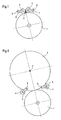
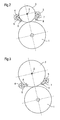
- a winding machine ( Fig. 1 - 4th ) has a support roller 1, which is positioned substantially vertically below a winding tube 2.
- the winding tube 2 is connected to a winding of a material web to a winding roll 3 ( Fig. 2-4 ).
- Side of the winding tube 2 are two support rollers 4, 5 on the winding tube 2 and on the winding roller 3 at.
- the support rollers 4, 5 are mounted in each case by means of rockers 6, 7 pivotable about guide points 8 and 9, respectively.
- the guide points 8 and 9 of the rockers 6, 7 are in this case above the axis of the first support roller first
- the coiled cores 2 are arranged side by side in the winding tube set from both sides Guiding heads tensioned in the axial direction.
- the individual winding tube 2 or a plurality of winding tubes 2 is located on or in the vicinity of the zenith, ie the uppermost point, on the circumference of the support roller 1.
- the support rollers 4, 5 hold them in position and provide the necessary line loads for transmitting the torques necessary for the winding structure.
- the back-up rolls 4, 5 have a smaller diameter than the back-up roll 1.
- the support rollers 4, 5 preferably pivot on a circular path to the outside.
- the winding tubes 2 are guided on a tilted to the vertical guide upwards.
- the back-up rollers can also perform other forms of pivotal movements in other embodiments.
- the support rollers with increasing diameter of the winding roll 3 exert an ever decreasing pressure on the winding roll 3 and finally take over more and more the function of a support roller, as it has the support roller 1.
- the winding roller 3 grows substantially vertically above the support roller 1 upwards.
- one of them is position-controlled and the other pressure-controlled.
- each (not shown) measuring arrangements for determining the position or the contact pressure of the support rollers 4, 5 with respect to the winding roll 3 is present, the measurement results determined by each of control devices for controlling the optimum pressure and the optimal position of the support rollers 4, the fifth pass on.
- the back-up rollers 4, 5 exert a controllable pressure on the winding roll 3 with increasing diameter of the winding roll 3 and finally more and more assume the function of a supporting roll, such as the back-up roll 1.
- the pressures are chosen so that the specific nip loads of all three back-up rolls 1, 4 and 5 are as low as possible be kept to avoid the winding errors or to produce bobbins with larger diameters can.
Landscapes
- Winding Of Webs (AREA)
- Replacement Of Web Rolls (AREA)
- Unwinding Webs (AREA)
- Rolls And Other Rotary Bodies (AREA)
Claims (4)
- Machine d'enroulement à cylindre porteur destinée à enrouler une nappe de matériau, en particulier une nappe de papier ou de carton, sur un mandrin (2) pour former un rouleau (3), au moyen d'un premier cylindre de soutien (1) disposé au moins essentiellement en dessous du rouleau (3), un deuxième et un troisième cylindre de soutien (4, 5) qui forment chacun un interstice avec le rouleau (3) étant disposés sur les deux côtés du rouleau (3) au-dessus du premier cylindre de soutien (1), le deuxième et le troisième cylindre de soutien (4, 5) étant disposées de manière à pouvoir pivoter par rapport au rouleau (3) sur des bielles oscillantes (6, 7) respectives qui présentent des points de guidage (8, 9),
caractérisé en ce que
les points de guidage (8, 9) des bielles oscillantes (6, 7) sont situés au-dessus de l'axe du premier cylindre de soutien (1). - Machine d'enroulement à cylindre porteur selon la revendication 1, caractérisé en ce que le deuxième et le troisième cylindre de soutien (4, 5) ont un diamètre plus petit que celui du premier cylindre de soutien (1).
- Machine d'enroulement à cylindre porteur selon les revendications 1 ou 2, caractérisé en ce que le deuxième et le troisième cylindre de soutien (4, 5) repoussent le rouleau (3) ou soutiennent ce dernier élastiquement, en particulier au moyen d'un ressort, d'un vérin pneumatique ou hydraulique ou d'un revêtement élastique du deuxième et du troisième cylindre de soutien (4, 5).
- Machine d'enroulement à cylindre porteur selon l'une des revendications 1 à 3, caractérisé en ce que le deuxième cylindre de soutien (4) est disposé en position régulée par rapport au rouleau (3) et le troisième cylindre de soutien (5) est doté d'une régulation de la poussée linéaire.
Applications Claiming Priority (1)
| Application Number | Priority Date | Filing Date | Title |
|---|---|---|---|
| DE102004000057A DE102004000057A1 (de) | 2004-11-26 | 2004-11-26 | Tragwalzen-Wickelmaschine |
Publications (2)
| Publication Number | Publication Date |
|---|---|
| EP1661835A1 EP1661835A1 (fr) | 2006-05-31 |
| EP1661835B1 true EP1661835B1 (fr) | 2008-07-02 |
Family
ID=35886891
Family Applications (1)
| Application Number | Title | Priority Date | Filing Date |
|---|---|---|---|
| EP05109925A Expired - Lifetime EP1661835B1 (fr) | 2004-11-26 | 2005-10-25 | Bobineuse à rouleaux porteurs |
Country Status (3)
| Country | Link |
|---|---|
| EP (1) | EP1661835B1 (fr) |
| AT (1) | ATE399733T1 (fr) |
| DE (2) | DE102004000057A1 (fr) |
Families Citing this family (1)
| Publication number | Priority date | Publication date | Assignee | Title |
|---|---|---|---|---|
| CN118753898B (zh) * | 2024-09-09 | 2025-02-07 | 精箔(洛阳)新材料科技有限公司 | 一种高精度电池箔精切机收卷机构 |
Family Cites Families (8)
| Publication number | Priority date | Publication date | Assignee | Title |
|---|---|---|---|---|
| DE2248816A1 (de) * | 1972-09-12 | 1974-04-11 | Fatra N P | Vorrichtung zum automatischen aufwickeln von bandartigen gebilden |
| DD154777A3 (de) * | 1980-08-18 | 1982-04-21 | Frank Riessland | Vorrichtung zum stangenlosen aufwickeln von mehrlagigen laengsgeschnittenen papierbahnen |
| DE3221929C2 (de) * | 1982-06-11 | 1990-04-19 | J.M. Voith Gmbh, 7920 Heidenheim | Doppeltragwalzen-Wickelmaschine |
| JPS6357463A (ja) * | 1986-08-27 | 1988-03-12 | Shimizu Seisakusho:Kk | トイレツトペ−パロ−ルの連続自動巻き取り方法及びその装置 |
| DE58901786D1 (de) * | 1988-03-02 | 1992-08-13 | Alzmetall Werkzeugmasch | Kompaktaufbau einer saeulenbohrmaschine. |
| FI100467B (fi) | 1994-05-26 | 1997-12-15 | Valmet Corp | Menetelmä ja laite rainan rullauksessa |
| DE19750539C1 (de) * | 1997-11-14 | 1999-07-15 | Voith Sulzer Finishing Gmbh | Wickeleinrichtung und Wickelverfahren, insbesondere für einen Rollenschneider |
| DE10115862A1 (de) | 2001-03-30 | 2002-10-17 | Jagenberg Papiertech Gmbh | Wickelmaschine zum Aufwickeln einer Materialbahn, insbesondere einer Papier- oder Kartonbahn, zu Wickelrollen |
-
2004
- 2004-11-26 DE DE102004000057A patent/DE102004000057A1/de not_active Withdrawn
-
2005
- 2005-10-25 DE DE502005004566T patent/DE502005004566D1/de not_active Expired - Fee Related
- 2005-10-25 AT AT05109925T patent/ATE399733T1/de not_active IP Right Cessation
- 2005-10-25 EP EP05109925A patent/EP1661835B1/fr not_active Expired - Lifetime
Also Published As
| Publication number | Publication date |
|---|---|
| DE102004000057A1 (de) | 2006-06-08 |
| ATE399733T1 (de) | 2008-07-15 |
| DE502005004566D1 (de) | 2008-08-14 |
| EP1661835A1 (fr) | 2006-05-31 |
Similar Documents
| Publication | Publication Date | Title |
|---|---|---|
| DE3639244C2 (de) | Tragwalzenwickelapparat für bewegte Bahnen | |
| DE3539980C2 (de) | Verfahren und Vorrichtung zur Steuerung eines Papierbahnaufrollers | |
| EP2557061A2 (fr) | Bobinoir et son procédé de commande | |
| EP0679595A1 (fr) | Rouleau de support pour une machine d'enroulage | |
| EP1900663B1 (fr) | Procédé d'enroulage d'une bande | |
| DE69608909T2 (de) | Zentrumtreibungsgerät für eines papierwicklersystem | |
| EP1900661A2 (fr) | Bobineuse | |
| EP2436626A2 (fr) | Dispositif d'enroulement de rouleaux et procédé de fabrication de rouleaux d'enroulement | |
| AT506493B1 (de) | Verfahren zum aufrollen einer papier- oder kartonbahn, und rollapparat | |
| EP1661835B1 (fr) | Bobineuse à rouleaux porteurs | |
| EP2088106B1 (fr) | Dispositif d'enroulement pour une une bande de matériau | |
| DE69901540T2 (de) | Verfahren zum aufwickeln einer bahn | |
| EP0942889B1 (fr) | Bobineuse pour enrouler une bande de materiau, notamment une bande de papier ou de carton pour former un rouleau bobine | |
| DE60110842T2 (de) | Verfahren und vorrichtung zum aufwickeln einer papier- oder kartonbahn | |
| EP1683749B1 (fr) | Bobineuse avec cylindres porteurs | |
| EP2113479B1 (fr) | Procédé de transfert d'une bande de matériau déroulante et machine d'enroulement destinée à l'exécution du procédé | |
| EP0421232A1 (fr) | Méthode et dispositif pour enrouler une bande de feuille | |
| DE102006043649B4 (de) | Wickelmaschine | |
| EP1650148A2 (fr) | Machine d'enroulement | |
| EP1710182A2 (fr) | Bobineuse à cylindres porteurs | |
| DE19944703A1 (de) | Verfahren zum Aufwickeln einer laufenden Materialbahn | |
| EP1657193B1 (fr) | Dispositif d'enroulage de bobines et procédé pour l'enroulement de bobines | |
| EP3962847B1 (fr) | Poste de déroulement | |
| DE102008053467A1 (de) | Mit einem Druckwalzenbalken und einer Druckwalze versehener Aufroller vom Tragwalzentyp und Verfahren | |
| DE102021121803A1 (de) | Kernverriegelungssystem |
Legal Events
| Date | Code | Title | Description |
|---|---|---|---|
| PUAI | Public reference made under article 153(3) epc to a published international application that has entered the european phase |
Free format text: ORIGINAL CODE: 0009012 |
|
| AK | Designated contracting states |
Kind code of ref document: A1 Designated state(s): AT BE BG CH CY CZ DE DK EE ES FI FR GB GR HU IE IS IT LI LT LU LV MC NL PL PT RO SE SI SK TR |
|
| AX | Request for extension of the european patent |
Extension state: AL BA HR MK YU |
|
| RAP1 | Party data changed (applicant data changed or rights of an application transferred) |
Owner name: VOITH PATENT GMBH |
|
| 17P | Request for examination filed |
Effective date: 20061130 |
|
| AKX | Designation fees paid |
Designated state(s): AT DE FI FR IT SE |
|
| 17Q | First examination report despatched |
Effective date: 20070903 |
|
| GRAP | Despatch of communication of intention to grant a patent |
Free format text: ORIGINAL CODE: EPIDOSNIGR1 |
|
| GRAS | Grant fee paid |
Free format text: ORIGINAL CODE: EPIDOSNIGR3 |
|
| GRAA | (expected) grant |
Free format text: ORIGINAL CODE: 0009210 |
|
| AK | Designated contracting states |
Kind code of ref document: B1 Designated state(s): AT DE FI FR IT SE |
|
| REF | Corresponds to: |
Ref document number: 502005004566 Country of ref document: DE Date of ref document: 20080814 Kind code of ref document: P |
|
| REG | Reference to a national code |
Ref country code: SE Ref legal event code: TRGR |
|
| PGFP | Annual fee paid to national office [announced via postgrant information from national office to epo] |
Ref country code: DE Payment date: 20081022 Year of fee payment: 4 |
|
| PGFP | Annual fee paid to national office [announced via postgrant information from national office to epo] |
Ref country code: AT Payment date: 20081015 Year of fee payment: 4 Ref country code: FI Payment date: 20081015 Year of fee payment: 4 |
|
| PGFP | Annual fee paid to national office [announced via postgrant information from national office to epo] |
Ref country code: SE Payment date: 20081014 Year of fee payment: 4 |
|
| PLBE | No opposition filed within time limit |
Free format text: ORIGINAL CODE: 0009261 |
|
| STAA | Information on the status of an ep patent application or granted ep patent |
Free format text: STATUS: NO OPPOSITION FILED WITHIN TIME LIMIT |
|
| 26N | No opposition filed |
Effective date: 20090403 |
|
| REG | Reference to a national code |
Ref country code: FR Ref legal event code: ST Effective date: 20090630 |
|
| PG25 | Lapsed in a contracting state [announced via postgrant information from national office to epo] |
Ref country code: FR Free format text: LAPSE BECAUSE OF NON-PAYMENT OF DUE FEES Effective date: 20081031 |
|
| PGFP | Annual fee paid to national office [announced via postgrant information from national office to epo] |
Ref country code: IT Payment date: 20081031 Year of fee payment: 4 |
|
| EUG | Se: european patent has lapsed | ||
| PG25 | Lapsed in a contracting state [announced via postgrant information from national office to epo] |
Ref country code: DE Free format text: LAPSE BECAUSE OF NON-PAYMENT OF DUE FEES Effective date: 20100501 |
|
| PG25 | Lapsed in a contracting state [announced via postgrant information from national office to epo] |
Ref country code: AT Free format text: LAPSE BECAUSE OF NON-PAYMENT OF DUE FEES Effective date: 20091025 Ref country code: FI Free format text: LAPSE BECAUSE OF NON-PAYMENT OF DUE FEES Effective date: 20091025 |
|
| PG25 | Lapsed in a contracting state [announced via postgrant information from national office to epo] |
Ref country code: IT Free format text: LAPSE BECAUSE OF NON-PAYMENT OF DUE FEES Effective date: 20091025 |
|
| PG25 | Lapsed in a contracting state [announced via postgrant information from national office to epo] |
Ref country code: SE Free format text: LAPSE BECAUSE OF NON-PAYMENT OF DUE FEES Effective date: 20091026 |