EP1661844A1 - Verfahren für Kranbedienung - Google Patents
Verfahren für Kranbedienung Download PDFInfo
- Publication number
- EP1661844A1 EP1661844A1 EP06001965A EP06001965A EP1661844A1 EP 1661844 A1 EP1661844 A1 EP 1661844A1 EP 06001965 A EP06001965 A EP 06001965A EP 06001965 A EP06001965 A EP 06001965A EP 1661844 A1 EP1661844 A1 EP 1661844A1
- Authority
- EP
- European Patent Office
- Prior art keywords
- cargo
- point
- crane
- jib
- target position
- Prior art date
- Legal status (The legal status is an assumption and is not a legal conclusion. Google has not performed a legal analysis and makes no representation as to the accuracy of the status listed.)
- Withdrawn
Links
Images

Classifications
-
- B—PERFORMING OPERATIONS; TRANSPORTING
- B66—HOISTING; LIFTING; HAULING
- B66C—CRANES; LOAD-ENGAGING ELEMENTS OR DEVICES FOR CRANES, CAPSTANS, WINCHES, OR TACKLES
- B66C13/00—Other constructional features or details
- B66C13/04—Auxiliary devices for controlling movements of suspended loads, or preventing cable slack
- B66C13/06—Auxiliary devices for controlling movements of suspended loads, or preventing cable slack for minimising or preventing longitudinal or transverse swinging of loads
- B66C13/063—Auxiliary devices for controlling movements of suspended loads, or preventing cable slack for minimising or preventing longitudinal or transverse swinging of loads electrical
-
- B—PERFORMING OPERATIONS; TRANSPORTING
- B66—HOISTING; LIFTING; HAULING
- B66C—CRANES; LOAD-ENGAGING ELEMENTS OR DEVICES FOR CRANES, CAPSTANS, WINCHES, OR TACKLES
- B66C13/00—Other constructional features or details
- B66C13/18—Control systems or devices
- B66C13/48—Automatic control of crane drives for producing a single or repeated working cycle; Program control
Definitions
- the present invention relates to a method for operating a crane for handling cargo containers, a controlling device for a crane, and a crane provided with the control device.
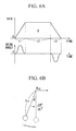
- FIGS. 5A and 5B and 6A and 6B A conventional method for operating a crane will be explained with reference to FIGS. 5A and 5B and 6A and 6B.
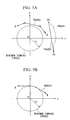
- FIG. 5A is a diagram showing tracks.of a jib point (an end portion of the jib) when a cargo is moved in a straight line at one time or a plurality of times.
- FIG 5B is a diagram showing a track of a jib point when a cargo is moved using a tangent of a circle having a minimum turning radius (hereinafter also referred to as a minimum turning circle).
- FIG. 6A is a diagram showing graphs which indicate the relationship between the moving rate of the jib end portion and time, and between a swinging angle of a hoisted cargo relative to the vertical direction and time.
- FIG. 6B is a schematic diagram showing a model of a moving pendulum.
- the symbol O indicates the center of turning a crane, i.e., the center of the jib operating radius in a cargo handling operation using the crane.
- the symbols A, and A indicate initial positions of a cargo
- the symbols B, and B1 indicate target positions of a cargo.
- the circles having a radius r 0 shown in the figure indicate a minimum turning circle of a crane, and this means that a handling operation for a cargo cannot be performed within the circle due to the mechanical restriction of the crane.
- the track 3 of the jib point shown in FIG. 5A is described in Japanese Laid-Open Patent Application No. 2000-38286.
- a crane moves a cargo while making a polygonal linear motion, which means a combination of linear motions, by means of turning and jib hoisting operations. More specifically, the jib point of a crane hoists a cargo at the initial position A, and turns to the right hand side direction around the rotation center O in the figure.
- the shortest track between the initial position A and the target position B is, of course, a straight line connecting the position A with the position B.
- the crane moves the cargo so as to avoid the minimum turning circle while increasing the operation radius in the direction separating away from the rotation center O.
- the transfer track of the jib point is linear, and the cargo is moved by a combination of the jib hoisting and turning operations.
- the moving direction of the jib point is changed so as to move along the minimum turning circle.
- the transfer track of the jib point is also made linear, and the cargo is moved by a combination of jib bending and turning operations.
- the moving direction of the jib point is further changed half way so that the cargo may be linearly moved towards the target position B.
- the track 3 forms a part of a polygonal shape, which is formed by a combination of a plurality of linear lines, and the cargo is eventually delivered to the target position B.
- the transfer track of a cargo is a linear line connecting the initial position A 1 and the target position B 1.
- the initial position A1 and the target position B1 are located relatively far from the minimum turning circle, or the moving distance of a cargo is relatively short.
- the hoisting operation of the jib is not used many times, and the operation of the crane is mainly carried out by turning operations of the jib.
- the jib hoisting operation is performed at the end of the track 1 in order to correct the shift in the radius direction.
- a trolley is used to move a cargo in a certain direction, and can be understood by swinging of a simple pendulum.
- the trolley accelerates during an acceleration time period t1, and then moves at a constant speed, which is the speed at the end of the acceleration, during a constant speed time period t2. Then, after the end of the constant speed time period t2, the trolley decelerates during a deceleration time period t3. Finally, the speed of the trolley reaches zero at the target position B1, and the trolley stops. Note that the area of the trapezoid S in FIG. 6A indicates a distance between the initial position A 1 and the target position B 1.
- the swinging angle ⁇ of a cargo will be explained with reference to FIG. 6B.
- the swinging angle of the cargo reaches a maximum while swinging in the direction opposite the moving direction, and then the swinging angle gradually decreases.
- the swinging angle of the cargo becomes zero.
- the swinging angle of the cargo reaches a maximum while swinging in the direction same as the moving direction, and then the swinging angle gradually decreases.
- the trolley stops the swinging angle of the cargo becomes zero.
- each of the acceleration time t1 and the deceleration time t2 is adjusted to be a multiple (an integer) of the period of a virtual pendulum shown in FIG. 6B. In this way, it becomes possible to stop the swing of a cargo since the swing period of the cargo matches the above-mentioned virtual pendulum.
- the track 4 of the jib point shown in FIG. 5B is disclosed in Japanese Laid-Open Patent Application No. 8-245164.
- the jib point of the crane linearly moves from the initial position A so as to approach to the minimum turning circle. Then, when the jib point reaches the minimum turning circle, it follows on a part of the circle. After this, the jib point separates away from the minimum turning circle half way, and linearly moves towards the target position B.
- the track 4 is formed by tangents of the minimum turning circle with respect to the initial position A and the target position B, and a part of the minimum turning circle. Accordingly, the track 4 is the shortest path connecting the initial position A and the target position B for the case where the cargo cannot pass through the minimum turning circle.
- a jib crane provided with a rotatable jib, such as a mobile harbor crane, a crawler crane, a wheel crane, and a tower crane
- the length of a rope varies in accordance with the degree of jib hoisting.
- an actual cargo handling operation using a crane it is necessary to avoid obstacles while moving a cargo, or to carry out a subtle positioning operation, and it is rare that the actual rope length, which is controlled by the operator of a crane, matches the estimated rope length.
- the rope length which is computed for stopping the swing of a cargo, changes from time to time, and the period of the hoisted cargo computed based on the virtual pendulum shifts from the period of the already computed virtual pendulum. Accordingly, it is often difficult to stop the swing of the hoisted cargo.
- both the tracks 3 and 4 shown in FIGS. 5A and 5B, respectively, are discontinuous moving paths, swing of a cargo may be generated in the direction different from the moving direction, or the cargo may be temporarily stopped when the direction of the cargo is changed in the middle of the track.
- the present invention takes into consideration the above-mentioned circumstances, and has as an object to provide a method for operating a crane, a controlling device for a crane, and a crane provided with the control device, by which the degree of swinging of a cargo in a handling operation using the crane is suppressed to a minimum level, and the working efficiency of the crane can be improved.
- the first aspect of the present invention provides a method for operating a crane provided with a jib having a jib point from which a cargo is hung via a rope member, the cargo being moved from an initial position to a target position to carry out a cargo handling operation, including: a hypothetical rope length setting step in which a hypothetical length of the rope member is set; a hypothetical acceleration pattern operation step in which a hypothetical acceleration pattern for swing angle of the rope member is operated for a case where the cargo is to be stopped at the target position provided that the hypothetical length of the rope member does not change and that the cargo is linearly moved from the initial position to the target position; a rope length change obtaining step in which a change in an actual length of the rope member is obtained; a jib point acceleration pattern operation step in which an acceleration pattern for the jib point is operated taking into account the change in the actual length of the rope member obtained in the rope length change obtaining step so that an acceleration pattern for swing angle of the rope member matches the hypothetical acceleration pattern obtained in
- a hypothetical acceleration pattern is obtained from the hypothetical acceleration pattern operation step so that the cargo is transferred from the initial position to the target position during a period in which a hypothetical pendulum having a hypothetical rope length returns to a zero point from the zero point. Then, the jib point acceleration pattern for the jib point is operated so that an acceleration pattern for a swing angle at the actual rope length obtained in the rope length change obtaining step matches the above-mentioned hypothetical acceleration pattern.
- the jib point acceleration pattern by which the swing of the cargo is stopped at the target position is always operated, and a command value to the jib moving step is output based on the result of the operation so as to stop the actual swing of the cargo due to the operation of the jib and crane.
- the swing of the cargo in the moving direction when the cargo is linearly transferred is stopped regardless of the change in the length of the rope member. Accordingly, an operator of the crane can perform manual operation, and hence the degree of flexibility in the operation is increased. Also, according to the above method, it becomes possible to transfer the cargo to the target position accurately and safely. Moreover, since the swing of the cargo is stopped, it becomes unnecessary for an operator to carry out a swing stop operation, and hence, labor for the operator is reduced. Furthermore, the efficiency in a cargo handling process may be improved since the cycle time required for repeatedly moving a cargo is shortened.
- the hypothetical rope length is set based on a maximum acceleration for linearly moving the jib point, the maximum acceleration being determined based on performance of the crane.
- the hypothetical rope length is a value that is operated in the hypothetical acceleration pattern operation step.
- the value can be arbitrary set, and determines the hypothetical acceleration pattern. Accordingly, a hypothetical acceleration in the hypothetical acceleration pattern is also obtained based on the hypothetical rope length, and can be arbitrary set.
- the hypothetical acceleration pattern be obtained so as to have as large an acceleration as possible in order to improve the workability of the crane.
- a most effective hypothetical acceleration pattern can be obtained by determining the hypothetical rope length based on the maximum acceleration of the jib movement, and in practice, the jib point is moved in the vicinity of the maximum acceleration for the crane.
- the hypothetical rope length is set based on the maximum acceleration for linearly moving the jib, which is determined based on the performance of the crane, it becomes possible to rapidly transfer a cargo using a maximum performance of the crane while avoiding a high load operation exceeding the performance of the crane. Accordingly, the efficiency in the cargo handling operation can be improved.
- ⁇ 0 is the hypothetical rope length
- ⁇ is the length of the rope member
- v is a velocity of the rope member
- ⁇ is an acceleration of the rope member
- a k0 is a jib point hypothetical acceleration in the hypothetical acceleration pattern operation step
- ⁇ is a swing angle of the cargo
- ⁇ is a swing angular velocity of the cargo
- g gravitational acceleration.
- the jib point acceleration a k is obtained using the above formula (1).
- the formula (1) it becomes possible to correspond to the change in the rope length which may vary at every moment. That is, the jib point acceleration a k is changed at every moment so as to correspond to the change in the actual rope length while recognizing the swing angle ⁇ of the cargo. In this manner, the period of the cargo is matched a swing-stop period obtained using the hypothetical acceleration pattern.
- the rope length ⁇ is substituted with a hypothetical rope length having a constant length
- the acceleration of the pendulum a k is substituted with a constant acceleration a ko , and a case is considered where the acceleration time is equal to a period of the hypothetical rope length.
- the formula (1) in this aspect of the present invention can be obtained by assuming that the velocity of the rope having the length ⁇ is v, the acceleration of the rope having the length ⁇ is ⁇ , and the swing angular velocity is ⁇ .
- the constant acceleration a ko can be arbitrary set, it is preferable to use a large constant acceleration a ko , taking into account, for instance, the limit in the power performance of the crane.
- the jib point acceleration a k in the jib point acceleration pattern operation step is expressed as an equation, it becomes possible to accurately obtain the jib point acceleration a k from each value obtained. Accordingly, it becomes possible to securely stop the swing of the cargo by linearly moving the jib point based on the results obtained.
- the fourth aspect of the present invention also provides a method for operating a crane in which a cargo is connected to a rope member hung from a jib point of a jib provided with the crane, the cargo being moved from an initial position to a target position to carry out a cargo handling operation, comprising the step of: transferring the cargo along an arc-shaped curve connecting the initial position and the target position, the arc-shaped curve not passing through a minimum turning circle which defines a range that a handling operation for the cargo is not possible due to a mechanical restriction of the crane.
- the jib point follows a track which is a part of an arc passing through the initial position and the target position, and hence the cargo is transferred along the arc.
- the jib point is moved along the arc by carrying out at least a hoisting operation of the jib and a revolution operation of the crane independently from each other at the same time.
- the arc be obtained so as to have as large a curvature radius as possible in order to reduce centrifugal force acting on the hoisted cargo.
- the hoisted cargo is moved along the arc connecting the initial position to the target position, it becomes possible to avoid the minimum turning circle and move the cargo from the initial position to the target position. Accordingly, the centrifugal force acting on the cargo is reduced, and hence, the cargo can be moved relatively quickly. Also, the degree of swing of the cargo can be decreased due to the reduced centrifugal force, and hence the time required to stop the swinging of the cargo can be shortened. Also, since there is no discontinuous point on the transfer track, the cargo can be stably moved without causing rapid and complicated swing thereof.
- the fifth aspect of the present invention provides the method for operating a crane according to the fourth aspect, wherein the arc-shaped curve contacts the minimum turning circle at one point.
- the jib points follows the arc track which passes both the initial position and the target position, and contacts the minimum turning circle at one point.
- the hoisted cargo moves along the arc track.
- the above-mentioned arc has the largest curvature radius among arcs connecting the initial position to the target position within the operation range of the crane.
- a minimum centrifugal force according to the moving speed thereof acts.
- the arc contacts the minimum turning circle of the crane at one point, it becomes possible to obtain an arc track having the largest radius. Accordingly, the centrifugal force acting on the cargo can be minimized and the transfer distance can be shortened. Therefore, for the case where the minimum turning circle interferes with the transfer track, it becomes possible to realize a crane loading operation of high efficiency.
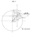
- the sixth aspect of the present invention provides the method for operating a crane according to the fifth aspect, wherein a transfer track of the cargo is projected onto an X-Y plane, and assuming that a coordinate of a revolution center of the crane is O (0, 0), a coordinate of the initial position A is (x A , y A ) , a coordinate of the target position B is (x B, y B ) , a coordinate of a middle point C between the point A and the point B is (x C, y C ) , a distance between the point A and the point C is L A, an angle between a perpendicular with respect to a straight line connecting the point A and the point B, which passes through the point C, and an x axis is ⁇ , a radius of the minimum turning circle of the crane is r 0 , a coordinate of a point D which is the center of the arc-shaped curve is D (x D , y D ), and the distance between the point C and the point D is L,
- the central coordinate of the point D is obtained using known coordinates or the position, i.e., the initial position A, the target position B, the middle point C between the point A and the point B, the distance L A between the point A and the point C, the angle ⁇ between the perpendicular with respect to the straight line connecting the point A and the point B passing through the point C, and the x axis, and the radius r 0 of the minimum turning circle of the crane.
- the jib point passes through the initial position A and the target position B, and follows the arc track which contact the minimum turning circle of the crane at one point. Accordingly the cargo is moved along the arc.
- FIG. 3 An arc indicating a track of the jib point is shown which connects the initial position A and the target position B, and contacts the minimum turning circle of the crane.
- a case is considered using an arbitrary point P (x, y) on the unknown arc, and a distance Lp between the point P and the point O.
- Lp x 2 + y 2
- L ⁇ ⁇ + ⁇ 2 ⁇ 4 ⁇ ⁇ 2 ⁇
- each of the formula explained above is obtained by determining the point C, which is a midpoint between the initial position A and the target position B, and the presence of the point D, which is the center of the arc to be obtained, on a perpendicular with respect to the straight line connecting A and B passing through the point C.
- the seventh aspect of the present invention also provides a method for operating a crane provided with a jib having a jib point from which a cargo is hung via a rope member, the cargo being moved from an initial position to a target position to carry out a cargo handling operation, comprising the steps of: operating a linear track connecting the initial position and the target position for the cargo, and carrying out a method for operating a crane according to one of the above-mentioned first to third aspects of the invention if it is determined that the operated linear track does not interfere with the minimum turning circle.
- a linear track connecting the initial position and the target position is computed by the operation. Then, it is determined whether the linear track obtained by the operation interferes with the minimum turning circle.
- the linear track is recognized as a suitable track for transferring the cargo, and the jib point is moved along the linear track so that the hoisted cargo is transferred from the initial position to the target position.
- the crane is operated under the swing stop control for the hoisted cargo in order to eliminate the swing of the cargo in the moving direction while obtaining the actual change in the length of the rope member.
- the eighth aspect of the present invention also provides a method for operating a crane provided with a jib having a jib point from which a cargo is hung via a rope member, the cargo being moved from an initial position to a target position to carry out a cargo handling operation, comprising the steps of: operating a linear track connecting the initial position and the target position for the cargo, and carrying out a method for operating a crane according to one of the fourth to sixth aspects of the invention if it is determined that the operated linear track interferes with the minimum turning circle.
- a linear track connecting the initial position and the target position is computed by the operation. Then, it is determined whether the linear track obtained by the operation interferes with the minimum turning circle.
- the linear track If it is determined that the linear track interferes with the minimum turning circle, i.e., the linear track passes through the minimum turning circle, the linear track is moved along the arc-shaped track explained in the above fourth to sixth aspects of the invention. Accordingly, the hoisted cargo is moved from the initial position to the target position along the arc-shaped track while being affected by a minimum centrifugal force.
- the ninth aspect of the present invention also provides a method for operating a crane provided with a jib having a jib point from which a cargo is hung via a rope member, the cargo being moved from an initial position to a target position to carry out a cargo handling operation, comprising the steps of: operating a linear track connecting the initial position and the target position for the cargo, carrying out a method for operating a crane according to one of the first to third aspects of the invention if it is determined that the operated linear track does not interfere with the minimum turning circle, and carrying out a method for operating a crane according to one of the fourth to sixth aspects of the invention if it is determined that the operated linear track interferes with the minimum turning circle.
- a linear track connecting the initial position and the target position is computed by the operation. Then, it is determined whether the linear track obtained by the operation interferes with the minimum turning circle.
- the linear track is recognized as a suitable track for transferring the cargo, and the jib point is moved along the linear track so that the hoisted cargo is transferred from the initial position to the target position.
- the crane is operated under the swing stop control for the hoisted cargo in order to eliminate the swing of the cargo in the moving direction while obtaining the actual change in the length of the rope member.
- the linear track is moved along the arc-shaped track explained in the above fourth to sixth aspects of the invention. Accordingly, the hoisted cargo is moved from the initial position to the target position along the arc-shaped track.
- the tenth aspect of present invention provides a control device for a crane which carries out a handling operation for a cargo connected to a rope member hung from a jib point of a jib provided with the crane, the cargo being moved from an initial position to a target position
- the control device comprising: a rope length change obtaining unit which obtains a change in an actual length of the rope member; a jib point acceleration pattern operation unit which sets a hypothetical length of the rope member, operates a hypothetical acceleration pattern for swing angle of the rope member for a case where the cargo is to be stopped at the target position provided that the hypothetical length of the rope member does not change and that the cargo is linearly moved from the initial position to the target position, and operates an acceleration pattern for the jib point taking into account the change in the actual length of the rope member obtained by the rope length change obtaining unit so that an acceleration pattern for swing angle of the rope member matches the operated hypothetical acceleration pattern; and a linear operation command unit which linearly moves the jib point based on the
- the hypothetical acceleration pattern is derived by the jib point acceleration pattern operation unit so that the cargo reaches from the initial position to the target position while a hypothetical pendulum having a hypothetical rope length returns to a lowest point from the lowest point. Then, the jib point acceleration pattern is operated so that the acceleration pattern of a swing angle of the rope member having an actual length obtained by the rope length change obtaining unit matches the above-mentioned hypothetical acceleration pattern.
- the jib point acceleration pattern by which the swing of the cargo is stopped at the target position is operated, and a command value for the linear operation command unit is output based on the operation result so that the actual movement of the jib point is controlled to stop the swing of the hoisted cargo.
- the above control device it becomes possible to eliminate the swing in the moving direction, which may be caused when the cargo is linearly transferred, regardless of the change in the length of the rope member. Therefore, it becomes possible for an operator to manually operated the crane, and the flexibility in the operation of the crane is increased. Also, in this way it becomes possible to transfer the cargo to the target position reliably and safely. Moreover, since the crane is controlled to stop the swing of the cargo, the labor for the operator is reduced. Furthermore, the efficiency in a cargo handling process may be improved since the cycle time required for repeatedly moving a cargo is shortened.
- the eleventh aspect of the present invention also provides a control device for a crane which carries out a handling operation for a cargo connected to a rope member hung from a jib point of a jib provided with the crane, the cargo being moved from an initial position to a target position, the control device comprising: an arc operation command unit which controls a revolution operation of the crane and a hoisting operation of the jib along an arc shaped curve connecting the initial position and the target position.
- the jib point follows the arc-shaped track from the initial position to the target position by the arc operation command unit, and the hoisted cargo is transferred along the arc-shaped track.
- the arc operation command unit orders these operations.
- the arc-shaped track ordered by the arc operation command unit to the crane have a large radius of curvature.
- the control device for a crane includes the arc operation command unit which controls a revolution operation of the crane and a hoisting operation of the jib along an arc shaped curve connecting the initial position and the target position, it becomes possible to move the hoisted cargo from the initial position to the target position along a large arc avoiding the minimum turning circle. In this manner, the centrifugal force acting on the hoisted cargo is reduced, and the cargo can be quickly transferred to the target position. Also, since the centrifugal force is reduced, it becomes possible to decrease the swing of the hoisted cargo, and hence to reduce the labor of the operator. Moreover, since there is no discontinuous points on the transfer track, complicated control is not necessary to stop the swing of the cargo, and hence, the swing stop control can be simplified.
- the twelfth present invention also provides a control device for a crane which carries out a handling operation for a cargo connected to a rope member hung from a jib point of a jib provided with the crane, the cargo being moved from an initial position to a target position
- the control device comprising: a track determination unit which operates a linear line connecting the initial position and the target position, and outputs a positional relationship with respect to a minimum turning circle of the crane, a rope length change obtaining unit which obtains a change in an actual length of the rope member; a jib point acceleration pattern operation unit which sets a hypothetical length of the rope member, operates a hypothetical acceleration pattern for swing angle of the rope member for a case where the cargo is to be stopped at the target position provided that the hypothetical length of the rope member does not change and that the cargo is linearly moved from the initial position to the target position, and operates an acceleration pattern for the jib point taking into account the change in the actual length of the rope member obtained by the rope length change obtaining
- the track determination unit determines the track for transferring the cargo from the initial position to the target position, and if it is determined that a linear movement is possible, it selects the linear operation command unit to linearly move the jib point.
- the track determination unit determines that it is not possible to linearly move the cargo from the initial position to the target position, i.e., if it is determined that the linear track connecting the initial position to the target position passes through the minimum turning circle, the track determination unit selects the arc operation command unit for the operation of the crane. Then, the arc operation command unit moves the jib point along an arc-shaped track which avoids the minimum turning circle.
- a transfer track which is most suitable for moving the jib point from the initial position to the target position is selected.
- the swing of the hoisted cargo is eliminated, and when the arc-shaped track is selected, the centrifugal force applied to the cargo is reduced. In both cases, the moving range of the jib point is increased to realize high efficiency in the cargo handling operation.
- the thirteenth aspect of the present invention provides a crane which carries out a handling operation for a cargo connected to a rope member hung from a jib point of a jib provided with the crane, the cargo being moved from an initial position to a target position, the crane comprising: a control device for a crane as set forth in one of the above-mentioned tenth to twelfth aspects of the present invention.
- a track for a cargo by which the swing of the cargo is eliminated or the centrifugal force applied to the cargo is minimized is selected among various tracks for transferring the cargo from the initial position to the target position, and a cargo handling operation is carried out.
- the moving range of the jib point can be increased by stopping the swing of the cargo, and it becomes possible to provide a crane which is capable of contributing the improvement in workability as well as the reduction in the labor of the operator.
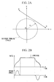
- FIG. 1 is a diagram showing a schematic structure of a mobile harbor crane 1 according to an embodiment of the present invention.
- FIGS. 2A and 2B and FIG. 3 are diagrams showing tracks of a jib point H of the mobile crane.
- FIG. 2A is a plan view indicating a linear movement of the jib point H.
- FIG. 2B is a pattern diagram showing the speed of the crane during operation thereof.
- FIG. 3 is a plan view showing an arc track of the jib point H and a manner of obtaining the track.
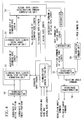
- FIG. 4 is a flowchart showing the flow of command signals from a control unit 10 when swing of a cargo is stopped.
- the numeral 1 shown in FIG. 1 indicates a mobile harbor crane (hereinafter also simply referred to as a "body”) which may be suitably used in a harbor facility as harbor equipment.
- the body 1 of the mobile harbor crane mainly includes a carrier frame 11 provided with a plurality of outriggers 12, a revolving frame 13 and a main frame 14, each of which is mounted on the carrier frame 11, and a jib 2 attached to the main frame 14.
- the carrier frame 11 secures the stability of the body 1 by means of the plurality of the outriggers 12, each of which protrude from both side of the carrier frame 11 in a vertical direction with respect to the longitudinal direction thereof.
- the crane can move around the yard of the harbor by means of wheels (not shown in the figure).
- Swing bearings of circular shape are.provided at substantially the center portion of the carrier frame 11, and the revolving frame 13 is mounted on the carrier frame 11 via the swing bearings.
- Gear racks are formed around the swing bearings and pinions (not shown in the figures), which are attached to a revolving driving unit (not shown in the figures), are engaged with the pinions.
- the revolving driving unit is attached to the revolving frame 13 side.
- the revolving frame 13 is rotatable 360° around the center of the swinging bearings due to the rotation of the pinions.
- the center of the swinging bearings means the rotation center O, and indicates the center of the operating radius of the crane carrying out the handling operation of a cargo.
- a revolution angle detection device 5a which detects the revolution direction of the revolving frame 13 with respect to the carrier frame 11 is disposed in the vicinity of the revolving center O of the revolving frame 13.
- the revolution angle detection device 5a is connected to the control unit 10, which will be described later, by a cable indicated by dotted lines.
- the main frame 14 On the revolving frame 13, the main frame 14, a winch 4, a cylinder 6, and an operation room (not shown in the figure) are mainly provided.
- the main frame 14 rotatably supports a base end portion of the jib 2.
- the winch 4 winds up a rope 3 (also referred to as a "wire") connected to a hoisted cargo G.
- the cylinder 6 hoists the jib 2, and an operator occupies the operation room to perform crane operations.
- the winch 4 is provided with an encoder 4a (means for obtaining a change in rope length) which detects a state of the length of the rope 3.
- the encoder 4a is connected to the control unit 10, which will be described later, by a cable indicated by the dotted lines.
- the main frame 14 has a truss structure in which a plurality of rod type members are combined.
- the base end portion of the jib 2 (the left hand side in the figure) is attached to substantially the middle position of the main frame 14 via jib foot pins (not shown in the figures).
- a hoisting angle detection device 2a which detects the hoisting angle of the jib 2, is disposed at a side of the jib foot pin or of the jib 2.
- the hoisting angle detection device 2a is connected to the control unit 10, which will be described later, by the cable indicated by the dotted lines.
- the jib 2 has a long shape with a truss structure, and the base end portion of the jib 2 is rotatably supported by the main frame 14 as explained above. Also, an end portion of the cylinder 6 at the rod side is rotatably attached to an underside position of the base end portion of the jib 2 slightly shifted towards the jib point side via pins (not shown in the figure). In this manner, the jib 2 is supported. Another end portion of the cylinder 6 at the bottom side is rotatably attached to a front portion of the revolving frame 13 via pins (not shown in the figures).
- the jib 2 is hoisted with respect to the jib foot pin, which functions as the center, by extension and retraction operations of the cylinder 6, and the jib operating radius based on the jib point H is determined.
- An end of the rope 3 is connected to a hook (not shown in the figures) for hoisting a cargo G, and the rope is hung from the jib point H towards the cargo G. Also, the other end of the rope 3 is wound up by the winch 4 provided on the revolving frame 13.
- the cargo G may be moved up by the winding operation of the rope 3 utilizing a rotary operation of the winch 4. Also, the hoisted cargo G may be moved downwardly by rotating the winch 4 in the reverse direction.
- a control device for controlling the operation of the body 1 includes, in addition to the control unit 10, at least the above-mentioned revolution angle detection device 5a, the hoisting angle detection device 2a, and the encoder 4a.
- the operator for operating the crane inputs positional information of the initial position A at which the cargo G is placed, and the target position B to which the cargo G is moved prior to starting to operate the crane.
- the operation for inputting each position may be carried out using an X-Y plane including the revolving center O of the body 1 as a reference point, and the operator inputs each position using an operation panel which is equivalent to the X-Y plane.
- the positional information of the initial position A and the target position B is output to the control unit 10 of the crane.
- each coordinate data is output to the control unit 10 to obtain a linear line connecting the positions A and B.
- the minimum turning circle means a circle having a radius r 0 which indicates that the handling operation of a cargo is not possible within the circle due to the mechanical restriction of the crane, and which also indicates a movable range of the jib point H when the jib 2 is hoisted to the maximum degree.
- the jib point H is linearly moved in order to transfer the cargo G along the linear line obtained as mentioned above and as shown in FIG. 2A.
- an arc shaped transfer track as shown in FIG. 3 is selected as a track for the jib point H. This operation method will be described later in detail.
- the linear movement of the jib point H may be carried out by coupling the hoisting motion of the jib 2 with the rotation of the revolving frame 13.
- the operator since the operator does not want an extreme change in the height of the cargo G by the hoisting operation of the jib 2, the operator also operates the winch 4 so as to maintain a constant height of the cargo G.
- the operator may additionally carry out a raising and lowering operations of the cargo G in order to avoid obstacles in the transfer path or to maintain a certain distance of the cargo G from the ground.
- the coordinates of the initial position A and the target position B are transformed into coordinates for practice by means of the coordinate transformation unit 50.
- a standard rope length ⁇ 0 (a virtual rope length) which becomes a base for a virtual pendulum, is obtained at a standard rope length setting unit 51 by taking into account the acceleration limit, and the speed limit derived from the mechanical structure of the body 1, and the actual rope length ⁇ .
- the result obtained is output to a standard rope length swing stop pattern formation unit 52.
- the actual rope length ⁇ is also directly output to an actual rope length acceleration command computation unit 54 (a jib point acceleration pattern computation means) which will be explained later.
- the obtained standard rope length ⁇ 0 is directly output to the actual rope length acceleration command computation unit 54.
- a swing stop pattern (virtual acceleration pattern) by which the cargo G is moved from the initial position A to the target position B during the period in which the virtual pendulum at the standard rope length ⁇ 0 returns to the zero point from the zero point.
- the acceleration a ko of the virtual pendulum at the standard rope length ⁇ 0 is obtained, and this result is directly output to the actual rope length acceleration command computation unit 54, and is output to the standard rope length swing angle computation unit 53.
- Methods for obtaining the acceleration a ko and the standard rope length ⁇ 0 will be explained later in the section of computation processes.
- the acceleration a ko of the virtual pendulum at the standard rope length ⁇ 0 input into the standard rope length swinging angle computation unit 52 is used to obtain the swinging angle ⁇ of the virtual pendulum at the standard rope length ⁇ 0 , and this is output to the actual rope length acceleration command computation unit 54.
- the velocity v and the acceleration ⁇ of the actual length of the rope are obtained by means of the time measurement of the encoder 4a, which measures the actual rope length, and the result is output to the actual rope length acceleration command computation unit 54.
- the acceleration a ko of the virtual pendulum in the above equation (21) is defined, and by this definition of the acceleration a ko , and the standard rope length ⁇ 0 of the virtual pendulum may be obtained based on the acceleration limit due to the mechanical structure a max .
- the rope length is not limited as above, it has an advantage of utilizing the performance of the crane to its maximum.
- the acceleration command for the jib point H is obtained from time to time taking into account the actual length of the rope ⁇ , which varies in accordance with the above equation (20). Accordingly, the velocity command for the jib point H can be obtained by integrating the acceleration command. Also, the positional command for the movement of the jib point H can be obtained by further carrying out the integration process.
- the revolution angle command is output to a revolution driving device with reference to the output value of the revolution angle detection device 5a so as to prompt the revolution operation of the revolving frame 13 which includes the jib 2 attached to the main frame 14.
- the hoisting angle command is input to a coordinate transformation unit 56 for the length of the cylinder 6, and is converted into a length command for the cylinder 6 to prompt the expansion operation of the cylinder 6.
- the velocity pattern of the jib point H will be explained using an example.
- the swing period of the cargo is regarded as one unit during the acceleration, and the crane is operated in accordance with the acceleration pattern by which the swing of the cargo is stopped when the velocity becomes constant. If a hypothetical case is considered in which an unexpected lowering operation is carried out during the constant speed period, since the actual length of the rope 3 is varied as compared with an expected length thereof, the velocity pattern of the jib point H, i.e., the acceleration pattern, is changed accordingly.
- the dotted line shown in the figure indicates a case where the change in the length of the rope 3 is known in advance in accordance with the hoisting of the jib 2. That is, the velocity pattern is almost the same as that at the start of acceleration. However, if there is ari unexpected operation during the constant speed period, the acceleration pattern and the velocity pattern of the jib point H are changed as shown in the solid line shown in FIG. 2B. Accordingly, the swing of the cargo is suppressed and the cargo is transferred to the target point B.
- the crane is controlled in accordance with the swinging angle of the cargo, and the swinging angle of the cargo is not changed as shown in the figure.
- the point O (0, 0) indicates the revolution center
- the circle including the point O indicates a minimum turning circle having the radius of r 0
- the coordinate of the initial position A is (X A , y A )
- the coordinate of the target position B is (X B , y B )
- the coordinate of the middle point C between the point A and the point B is (x c , y c )
- the distance between the point A and the point C is L A
- the radius of the arc is R
- the coordinate of an arbitrary point P on the arc is (x, y)
- ⁇ indicates an angle between a perpendicular to the straight line connecting the point A and the point B, which passes through the point C, and the x axis.
- the distance between the point C and the point D is assumed to be L
- the distance between the point O and the point P is assumed to be Lp.
- the control unit 10 When it is determined by the above-mentioned operation that the straight line AB connecting the initial position A and the target position B passes through the minimum turning circle, the control unit 10 (refer to FIG. 1) starts operation to obtain an arc shaped track which connects the point A and the point B without passing through the minimum turning circle. Processes for moving the jib point H along the arc shaped tack will be explained.
- the radius R of the arc, and the center coordinate D of the arc with respect to the revolution center O can be obtained.
- an arc operation command unit 60 an arc operation command means
- the results of the operation are input into the coordinate transformation unit 55 to control the rotation operation of the revolving frame 13, and the hoisting operation of the jib 2 at the same time.
- the command relating to the hoisting operation of the jib 2 is output by being converted into a length command for the cylinder 6 via the coordinate transformation unit 56 for the cylinder 6.
- the jib point H is moved along the arc shown in FIG. 3 as the transfer track so that a handling operation of the cargo is carried out from the initial position A to the target position B.
- the arc shaped track for the cargo G touches the minimum turning circle only at a point and does not follow the minimum turning circle. That is, the arc shaped track has a radius R which is much larger than the radium r 0 . It is needless to say that the centrifugal force applied to the cargo G becomes smaller as the moving radius for the cargo G becomes larger.
- the method for obtaining the arc shaped track is not limited to this, and can be obtained as described below.
- the minimum turning circle having the radius r 0 can be defined by the hoisting of the jib 2 at the maximum degree. That is, since the minimum turning circle indicates a near-limit of the moving range of the jib 2 due to the mechanical structure thereof, there is a possibility that an accurate operation of the jib 2 becomes difficult depending on the situation due to, for instance, stuck of the cylinder 6.
- a most suitable transfer track of the cargo G can be obtained from the initial position A and the target position B, and the workability in the loading and unloading operations can be improved.
- the generation of swing of the hoisted cargo G can be suppressed to substantially zero regardless of the change in the length of the rope 3 due to the change in the acceleration. Accordingly, time required for stopping the swing of the cargo may be shortened, and the workability of the crane can be improved. Moreover, since the crane may be always operated in the vicinity of the acceleration limit due to the mechanical structure thereof, the cargo G may be transferred in a short amount of time while freely adjusting the height of the cargo G.
- the operator of the crane need not carry out an operation for stopping the swing of the cargo, or the labor necessary for such operation is significantly reduced.
- the operator of the crane is free to carry out raising and lowering operations for the cargo G during the operation, a more appropriate handling operation for the cargo may be realized.
- the hoisted cargo G may be moved along a continuous arc shaped track having a large radius R, it becomes possible to minimize the centrifugal force applied to the cargo G, and also the revolving speed can be increased without applying complicated and rapid inertia to the cargo G. Accordingly, the workability in the handling operation of the cargo G can be improved.
- time is reduced in a repeated operation of unloading the cargo G at the target point B and moving the jib back to the initial position A to load another cargo.
Landscapes
- Engineering & Computer Science (AREA)
- Mechanical Engineering (AREA)
- Automation & Control Theory (AREA)
- Control And Safety Of Cranes (AREA)
Applications Claiming Priority (2)
| Application Number | Priority Date | Filing Date | Title |
|---|---|---|---|
| JP2001352233A JP2003155192A (ja) | 2001-11-16 | 2001-11-16 | クレーンの運転方法及び制御装置並びにこれを備えたクレーン |
| EP20020025515 EP1314681B1 (de) | 2001-11-16 | 2002-11-13 | Verfahren für Kranbedienung |
Related Parent Applications (1)
| Application Number | Title | Priority Date | Filing Date |
|---|---|---|---|
| EP20020025515 Division EP1314681B1 (de) | 2001-11-16 | 2002-11-13 | Verfahren für Kranbedienung |
Publications (1)
| Publication Number | Publication Date |
|---|---|
| EP1661844A1 true EP1661844A1 (de) | 2006-05-31 |
Family
ID=19164441
Family Applications (2)
| Application Number | Title | Priority Date | Filing Date |
|---|---|---|---|
| EP20020025515 Expired - Lifetime EP1314681B1 (de) | 2001-11-16 | 2002-11-13 | Verfahren für Kranbedienung |
| EP06001965A Withdrawn EP1661844A1 (de) | 2001-11-16 | 2002-11-13 | Verfahren für Kranbedienung |
Family Applications Before (1)
| Application Number | Title | Priority Date | Filing Date |
|---|---|---|---|
| EP20020025515 Expired - Lifetime EP1314681B1 (de) | 2001-11-16 | 2002-11-13 | Verfahren für Kranbedienung |
Country Status (3)
| Country | Link |
|---|---|
| EP (2) | EP1314681B1 (de) |
| JP (1) | JP2003155192A (de) |
| DE (1) | DE60217621T8 (de) |
Cited By (2)
| Publication number | Priority date | Publication date | Assignee | Title |
|---|---|---|---|---|
| US7426423B2 (en) * | 2003-05-30 | 2008-09-16 | Liebherr-Werk Nenzing—GmbH | Crane or excavator for handling a cable-suspended load provided with optimised motion guidance |
| EP2436640A4 (de) * | 2009-08-27 | 2013-05-22 | Hunan Sany Intelligent Control | Steuerverfahren und -system sowie hakenverschiebungsvorrichtung |
Families Citing this family (10)
| Publication number | Priority date | Publication date | Assignee | Title |
|---|---|---|---|---|
| DE102006048988A1 (de) * | 2006-10-17 | 2008-04-24 | Liebherr-Werk Nenzing Gmbh, Nenzing | Steuerungssystem für einen Auslegerkran |
| DE102006052956B4 (de) * | 2006-11-09 | 2019-07-04 | Kuka Roboter Gmbh | Verfahren und Vorrichtung zum Bewegen einer freischwingenden Last von einem Start- zu einem Zielpunkt |
| CN103723629B (zh) * | 2013-12-31 | 2017-02-15 | 三一海洋重工有限公司 | 一种起重机和起重机钢丝绳防摇控制方法 |
| JP6449744B2 (ja) * | 2015-09-08 | 2019-01-09 | Jfeプラントエンジ株式会社 | クレーンの制御装置、及びクレーンの制御方法 |
| CN110436347B (zh) * | 2019-08-23 | 2020-08-04 | 武汉理工大学 | 一种桥式起重机双摆系统优化防摇控制方法 |
| EP4169865B1 (de) * | 2020-06-22 | 2025-02-26 | JFE Steel Corporation | Frachtkran, frachtkranschwenkverhinderungsverfahren und frachtförderverfahren |
| JP7314896B2 (ja) * | 2020-09-29 | 2023-07-26 | Jfeスチール株式会社 | 荷役搬送経路生成方法、荷役搬送クレーン及び荷役運搬方法 |
| CN116547227A (zh) * | 2020-11-30 | 2023-08-04 | 杰富意钢铁株式会社 | 货物装卸运送路径生成方法、货物装卸运送起重机及货物装卸运送方法 |
| JP7513999B2 (ja) * | 2021-04-27 | 2024-07-10 | 国立大学法人東京工業大学 | 制御装置、クレーン、及びクレーンの制御方法 |
| JP7645510B2 (ja) * | 2021-06-28 | 2025-03-14 | シンフォニアテクノロジー株式会社 | ジブクレーンの制御方法および制御システム |
Citations (3)
| Publication number | Priority date | Publication date | Assignee | Title |
|---|---|---|---|---|
| GB1470846A (en) * | 1973-05-09 | 1977-04-21 | Tokyo Keiki Kk | Method and apparatus for controlling a rotary crane |
| DE4025749A1 (de) * | 1990-08-14 | 1992-02-20 | Siemens Ag | Verfahren zum automatischen betreiben eines drehkrans |
| EP0732299A1 (de) * | 1995-03-13 | 1996-09-18 | MANNESMANN Aktiengesellschaft | Verfahren zur Auslegerführung eines Kranes mit Wippausleger |
Family Cites Families (6)
| Publication number | Priority date | Publication date | Assignee | Title |
|---|---|---|---|---|
| DE2231997C3 (de) * | 1972-06-29 | 1980-12-18 | Siemens Ag, 1000 Berlin Und 8000 Muenchen | Einrichtung zur Aufrechterhaltung eines zwischen zwei miteinander verknüpften Kranbewegungen bestehenden Verhältnisses |
| JP3080189B2 (ja) * | 1991-10-24 | 2000-08-21 | 石川島運搬機械株式会社 | ジブクレーンの荷振れ止め運転制御方法及びその装置 |
| US5961563A (en) * | 1997-01-22 | 1999-10-05 | Daniel H. Wagner Associates | Anti-sway control for rotating boom cranes |
| JP4183316B2 (ja) * | 1998-11-20 | 2008-11-19 | 三菱重工業株式会社 | 吊荷の振れ止め制御装置 |
| JP2000313586A (ja) * | 1999-04-30 | 2000-11-14 | Mitsubishi Heavy Ind Ltd | 吊荷の振れ止め制御装置 |
| JP2001278579A (ja) * | 2000-03-30 | 2001-10-10 | Fuso Koki Kk | 吊り荷の振れ止め制御方法および制御装置 |
-
2001
- 2001-11-16 JP JP2001352233A patent/JP2003155192A/ja active Pending
-
2002
- 2002-11-13 DE DE2002617621 patent/DE60217621T8/de active Active
- 2002-11-13 EP EP20020025515 patent/EP1314681B1/de not_active Expired - Lifetime
- 2002-11-13 EP EP06001965A patent/EP1661844A1/de not_active Withdrawn
Patent Citations (3)
| Publication number | Priority date | Publication date | Assignee | Title |
|---|---|---|---|---|
| GB1470846A (en) * | 1973-05-09 | 1977-04-21 | Tokyo Keiki Kk | Method and apparatus for controlling a rotary crane |
| DE4025749A1 (de) * | 1990-08-14 | 1992-02-20 | Siemens Ag | Verfahren zum automatischen betreiben eines drehkrans |
| EP0732299A1 (de) * | 1995-03-13 | 1996-09-18 | MANNESMANN Aktiengesellschaft | Verfahren zur Auslegerführung eines Kranes mit Wippausleger |
Cited By (3)
| Publication number | Priority date | Publication date | Assignee | Title |
|---|---|---|---|---|
| US7426423B2 (en) * | 2003-05-30 | 2008-09-16 | Liebherr-Werk Nenzing—GmbH | Crane or excavator for handling a cable-suspended load provided with optimised motion guidance |
| EP2436640A4 (de) * | 2009-08-27 | 2013-05-22 | Hunan Sany Intelligent Control | Steuerverfahren und -system sowie hakenverschiebungsvorrichtung |
| US8960462B2 (en) | 2009-08-27 | 2015-02-24 | Hunan Sany Intelligent Control Equipment Co., Ltd. | Controlling method, system and device for hook deviation |
Also Published As
| Publication number | Publication date |
|---|---|
| EP1314681B1 (de) | 2007-01-17 |
| DE60217621T2 (de) | 2007-10-31 |
| DE60217621D1 (de) | 2007-03-08 |
| EP1314681A1 (de) | 2003-05-28 |
| JP2003155192A (ja) | 2003-05-27 |
| DE60217621T8 (de) | 2008-05-15 |
Similar Documents
| Publication | Publication Date | Title |
|---|---|---|
| EP1314681B1 (de) | Verfahren für Kranbedienung | |
| US7185774B2 (en) | Methods and apparatus for manipulation of heavy payloads with intelligent assist devices | |
| RU2516812C2 (ru) | Устройство определения положения крюка и кран | |
| EP3766821B1 (de) | Kran und kransteuerungsverfahren | |
| CN109231016B (zh) | 一种建筑施工塔吊机避碰方法 | |
| CN107399674A (zh) | 悬挂式起重机的控制方法以及控制装置 | |
| EP3822221A1 (de) | Kran und kransteuerungsverfahren | |
| CN108358081B (zh) | 可实现自动化吊装的智能塔吊系统的工作方法 | |
| JP2022190556A (ja) | クレーン | |
| JP7513999B2 (ja) | 制御装置、クレーン、及びクレーンの制御方法 | |
| KR101384512B1 (ko) | 고소작업대의 선속도제어 방법 및 장치 | |
| US11858785B2 (en) | Crane | |
| CN116203943A (zh) | 具有在终点改变情况下灵活的重新规划功能的轨迹规划 | |
| WO1996026883A1 (en) | Boom storing and extending device for crane | |
| JP2760527B2 (ja) | クレーン制御装置 | |
| JP3241591B2 (ja) | クレーンの制御方法 | |
| CN205472297U (zh) | 一种桥式起重机吊钩钢丝绳偏摆角检测装置 | |
| JPH05139689A (ja) | ジブクレーンの荷振れ止め運転制御方法及びその装置 | |
| CA3083807C (en) | Crane controller | |
| SU1654244A2 (ru) | Указатель длины вытравленного грузового каната грузоподъемного средства | |
| JPH05330786A (ja) | クレーンの起伏停止制御装置 | |
| JP2684940B2 (ja) | ケーブルクレーンの制御方法 | |
| JP2628276B2 (ja) | 高所作業車乗用バケットの移動制御方法および装置 | |
| JPH10129982A (ja) | ジブクレーン | |
| JPH1160159A (ja) | 平行走行式ケーブルクレーンの制御方法 |
Legal Events
| Date | Code | Title | Description |
|---|---|---|---|
| PUAI | Public reference made under article 153(3) epc to a published international application that has entered the european phase |
Free format text: ORIGINAL CODE: 0009012 |
|
| AC | Divisional application: reference to earlier application |
Ref document number: 1314681 Country of ref document: EP Kind code of ref document: P |
|
| AK | Designated contracting states |
Kind code of ref document: A1 Designated state(s): AT BE BG CH CY CZ DE DK EE ES FI FR GB GR IE IT LI LU MC NL PT SE SK TR |
|
| AX | Request for extension of the european patent |
Extension state: AL LT LV MK RO SI |
|
| STAA | Information on the status of an ep patent application or granted ep patent |
Free format text: STATUS: THE APPLICATION HAS BEEN WITHDRAWN |
|
| 18W | Application withdrawn |
Effective date: 20061201 |