EP1661846A2 - Actionneur - Google Patents
Actionneur Download PDFInfo
- Publication number
- EP1661846A2 EP1661846A2 EP05021472A EP05021472A EP1661846A2 EP 1661846 A2 EP1661846 A2 EP 1661846A2 EP 05021472 A EP05021472 A EP 05021472A EP 05021472 A EP05021472 A EP 05021472A EP 1661846 A2 EP1661846 A2 EP 1661846A2
- Authority
- EP
- European Patent Office
- Prior art keywords
- spindle
- housing
- adjusting device
- pivot bearing
- load
- Prior art date
- Legal status (The legal status is an assumption and is not a legal conclusion. Google has not performed a legal analysis and makes no representation as to the accuracy of the status listed.)
- Granted
Links
Images

Classifications
-
- B—PERFORMING OPERATIONS; TRANSPORTING
- B66—HOISTING; LIFTING; HAULING
- B66F—HOISTING, LIFTING, HAULING OR PUSHING, NOT OTHERWISE PROVIDED FOR, e.g. DEVICES WHICH APPLY A LIFTING OR PUSHING FORCE DIRECTLY TO THE SURFACE OF A LOAD
- B66F3/00—Devices, e.g. jacks, adapted for uninterrupted lifting of loads
- B66F3/08—Devices, e.g. jacks, adapted for uninterrupted lifting of loads screw operated
- B66F3/18—Devices, e.g. jacks, adapted for uninterrupted lifting of loads screw operated actuated through worm gearings
-
- F—MECHANICAL ENGINEERING; LIGHTING; HEATING; WEAPONS; BLASTING
- F16—ENGINEERING ELEMENTS AND UNITS; GENERAL MEASURES FOR PRODUCING AND MAINTAINING EFFECTIVE FUNCTIONING OF MACHINES OR INSTALLATIONS; THERMAL INSULATION IN GENERAL
- F16H—GEARING
- F16H25/00—Gearings comprising primarily only cams, cam-followers and screw-and-nut mechanisms
- F16H25/18—Gearings comprising primarily only cams, cam-followers and screw-and-nut mechanisms for conveying or interconverting oscillating or reciprocating motions
- F16H25/20—Screw mechanisms
-
- F—MECHANICAL ENGINEERING; LIGHTING; HEATING; WEAPONS; BLASTING
- F16—ENGINEERING ELEMENTS AND UNITS; GENERAL MEASURES FOR PRODUCING AND MAINTAINING EFFECTIVE FUNCTIONING OF MACHINES OR INSTALLATIONS; THERMAL INSULATION IN GENERAL
- F16H—GEARING
- F16H25/00—Gearings comprising primarily only cams, cam-followers and screw-and-nut mechanisms
- F16H25/18—Gearings comprising primarily only cams, cam-followers and screw-and-nut mechanisms for conveying or interconverting oscillating or reciprocating motions
- F16H25/20—Screw mechanisms
- F16H2025/2037—Actuator supports or means for fixing piston end, e.g. flanges
-
- F—MECHANICAL ENGINEERING; LIGHTING; HEATING; WEAPONS; BLASTING
- F16—ENGINEERING ELEMENTS AND UNITS; GENERAL MEASURES FOR PRODUCING AND MAINTAINING EFFECTIVE FUNCTIONING OF MACHINES OR INSTALLATIONS; THERMAL INSULATION IN GENERAL
- F16H—GEARING
- F16H25/00—Gearings comprising primarily only cams, cam-followers and screw-and-nut mechanisms
- F16H25/18—Gearings comprising primarily only cams, cam-followers and screw-and-nut mechanisms for conveying or interconverting oscillating or reciprocating motions
- F16H25/20—Screw mechanisms
- F16H2025/2062—Arrangements for driving the actuator
- F16H2025/209—Arrangements for driving the actuator using worm gears
-
- Y—GENERAL TAGGING OF NEW TECHNOLOGICAL DEVELOPMENTS; GENERAL TAGGING OF CROSS-SECTIONAL TECHNOLOGIES SPANNING OVER SEVERAL SECTIONS OF THE IPC; TECHNICAL SUBJECTS COVERED BY FORMER USPC CROSS-REFERENCE ART COLLECTIONS [XRACs] AND DIGESTS
- Y10—TECHNICAL SUBJECTS COVERED BY FORMER USPC
- Y10T—TECHNICAL SUBJECTS COVERED BY FORMER US CLASSIFICATION
- Y10T74/00—Machine element or mechanism
- Y10T74/18—Mechanical movements
- Y10T74/18568—Reciprocating or oscillating to or from alternating rotary
- Y10T74/18576—Reciprocating or oscillating to or from alternating rotary including screw and nut
Definitions
- the invention relates to an adjusting device for positioning a load with a spindle and a spindle nut arranged on the spindle, wherein either the spindle nut is rotatably mounted in a gear housing and axially immovable and by rotation of the spindle nut, the spindle for positioning the load is axially adjustable or the spindle rotatably and axially non-displaceably mounted in the gear housing and the spindle nut for adjusting the load is axially adjustable by rotation of the spindle.
- Such adjusting devices are known and are also referred to as Spindelhubgetriebe, spindle nut gear or actuators. Such adjusting devices are used to position loads in the form of components or assemblies. For example, these adjusting devices are used in lifting tables, lifting blocks, height-adjustable stages, valves with motor-adjustable valve slides, motorized concrete formwork, etc.
- spindle nut gear In addition to spindle nut transmissions, in which the support nut is rotatably mounted in a gear housing and adjusted during its rotation a non-rotatable spindle in the axial direction, and spindle nut gear are known in which the spindle is rotatably mounted in the gear housing and arranged by rotation of the spindle one on your external thread and secured against rotation nut is adjusted in the axial direction of the spindle.
- the load is further pivotally connected to the spindle (in the case of an axially adjustable spindle) or the spindle nut (in the case of an axially adjustable spindle nut).
- a pivotable mounting of the adapter part connected to the transmission housing on the pivotable load and a pivotable mounting of the axially adjustable spindle or axially adjustable spindle nut on a stationary support member can be provided.
- Disadvantages of this conventional solution are the relatively high additional costs for the adapter part to be connected to the transmission housing, via which the pivot bearing is produced.
- the object of the invention is to provide an improved adjusting device of the type mentioned, in which, compared to conventional adjusting devices, a cost saving in the realization of pivoting operations of loads is achieved. According to the invention, this is achieved by an adjusting device having the features of claim 1.
- pivot bearing Due to the integration of the pivot bearing in the transmission housing, no additional adapter parts to be fastened to the transmission housing are required to form pivoting operations of loads, as a result of which a more cost-effective actuating device for pivoting operations is formed.
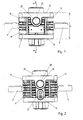
- a spindle nut 2 is rotatably supported and axially immovable in the gear housing 1 via Achsiallager 3, 4.
- the spindle nut 2 is arranged with its internal thread on the external thread of a spindle 5, which by axial rotation of the spindle nut 2, d. H. in the direction of its longitudinal axis 6 is adjustable.
- the external thread of the spindle 5 may be formed, for example in the form of a trapezoidal thread.
- this has an external toothing 7, which is in engagement with the toothing of a drive wheel 8.
- the external toothing 7 can, for example, as Worm gearing and the drive wheel 8 may be formed as a worm.
- the drive wheel 8 is driven via a drive shaft 9, which protrudes in the embodiment shown on opposite sides of the housing 10, 11 of the gear housing 1 from this.
- the rotatable mounting of the drive wheel 8 can be done for example by a rotatable mounting of the drive shaft 9 arranged on both sides of the drive wheel 8 radial bearings, which are not shown in the figures.
- the spindle 5 protrudes in the region of upper and lower housing sides 12, 13 out of the transmission housing 1.
- a lubricant can be introduced after unscrewing a screw plug 15.
- a lubricant can be introduced through the lubricating nipple 16 and the lubrication hole 17 also (equal or different) lubricant can be introduced.
- the protruding from the gear housing 1 section of the spindle 5, at the end of which the load to be adjusted is attached, may be surrounded by a corrugated or bellows 18, which is shown in Fig. 6 only by dashed lines.
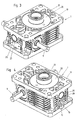
- the transmission housing 1 comprises a housing base part 19 and a housing cover 20 screwed to the housing base part, through which the spindle 5 is led out of the transmission housing 1 on a housing side 12.
- bushes 21, 22 are pressed.
- the sockets 21, 22 are spaced from the external thread of the spindle 5 by a gap. If a lateral load on the spindle 5 acts, so that it is pressed against the inner wall of the sleeve 21 and 22, the sleeve 21, 22 also serves for radial guidance of the spindle 5.
- the socket 21, 22 consists of a correspondingly lubricious material, preferably bronze.
- the housing base part 19 is formed as a metal casting.
- On opposite sides of the housing 23, 24 are blind holes 25, 26 arranged in the housing base part 19, in which piece-shaped pivot bearing bushings ( sliding bushes) 27, 28 are pressed.
- the pivot bearing bushings 27, 28 serve to receive pivot pins in order to pivotably mount the gear housing 1 in order to form a pivot drive.
- the pivot bearing bushings 27, 28 may be formed, for example, in the form of bronze-coated steel bushes.
- the axes 29 of the pivot bearing bushings 27, 28 are aligned with each other and are perpendicular to the longitudinal axis 6 of the spindle.
- the axes 29 of the pivot bearing bushings 27, 28 further perpendicular to the drive shaft 9, wherein the housing sides 23, 24, in which the blind holes 25, 26 are arranged with the pivot bearing bushings 27, 28, perpendicular to the housing sides 10, 11, which are penetrated by the drive shaft 9.
- the axes 29 of the pivot bearing bushes 27, 28 are less than half, preferably less than two-fifths, of the height h of the gear housing 1 measured from the load-side edge 30, 31 of the respective housing side 23 in the axial direction of the spindle 5. 24, where they are located, are removed. The deflection of the spindle 5 by the load acting on it is thereby kept as low as possible.
- the blind holes 25, 26 are formed during casting of the housing base portion 19 and subsequently drilled to the exact desired diameter. As a result, the pivot bushings 27, 28 are pressed.
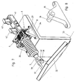
- FIG. 7 An embodiment of a possible application of a control device according to this embodiment is shown in FIG. 7.
- a load 32 is mounted pivotably about a pivot axis 33 on a stationary part 34.
- bearing plates 35 are mounted, which pivot pin 36 (see Fig. 8) have.
- the pivot pins 36 protrude into the on the opposite sides of the housing 23, 24 in the blind holes 25, 26 pressed pivot bearing bushings 27, 28, whereby the gear housing 1 about the axis 29 of the pivot bushings 27, 28 is pivotally mounted.
- a bearing plate 37 On the load 32, a bearing plate 37 is mounted, which has a bore which is penetrated by a pin 38 which projects through holes in a fork 39 and is secured by a split pin 40.
- the fork 39 is attached to the end of the spindle 5. In this way, the load 32 is pivotally connected to the spindle 5.
- a block (not visible in Fig. 7) be secured, but slidably in the square tube 41 but not rotatable relative to this is mounted to form a rotation for the spindle 5.
- the rotation of the spindle 5 can also be formed by the attachment to the load 32. With the projecting into the square tube 41 section of the spindle 25 further limit switches 42, 43 cooperate, which limit the pivot angle for the load 32.
- the drive shaft 9 is driven by a drive motor, not shown, whereby the spindle nut 2 is rotated by the drive wheel 8 and the spindle 5 is moved axially.
- the gear housing 1 pivots about the axis 29 of the pivot bearing bushing 27, 28. Furthermore, the load 32 pivots relative to the spindle 5 about the bolt 38th
- the housing base part 19 could also be made in several parts from a plurality of interconnected metal castings.
- the screw-on housing cover 20 could also be omitted in this case.
- a plurality of screw-on housing cover could be provided.
- a spindle nut 2 is rotatably but axially non-displaceably mounted in the gear housing to axially adjust the secured against rotation spindle.
- the spindle could be rotatably mounted in the transmission housing and axially non-displaceable and by means of a drive wheel which is connected to a drive shaft, are rotated.
- the spindle protrudes in such a training only on one side of the housing out of this.
- the arranged on the external thread of the spindle spindle nut is adjusted during the rotation of the spindle in the axial direction of the spindle.
- the spindle nut is hereby secured by its connection with the load to be adjusted against rotation.
Landscapes
- Engineering & Computer Science (AREA)
- Mechanical Engineering (AREA)
- General Engineering & Computer Science (AREA)
- Life Sciences & Earth Sciences (AREA)
- Geology (AREA)
- Structural Engineering (AREA)
- Gear Transmission (AREA)
- Transmission Devices (AREA)
- General Details Of Gearings (AREA)
Applications Claiming Priority (1)
| Application Number | Priority Date | Filing Date | Title |
|---|---|---|---|
| AT0083104U AT8083U1 (de) | 2004-11-17 | 2004-11-17 | Stelleinrichtung |
Publications (3)
| Publication Number | Publication Date |
|---|---|
| EP1661846A2 true EP1661846A2 (fr) | 2006-05-31 |
| EP1661846A3 EP1661846A3 (fr) | 2007-05-09 |
| EP1661846B1 EP1661846B1 (fr) | 2009-03-04 |
Family
ID=35406121
Family Applications (1)
| Application Number | Title | Priority Date | Filing Date |
|---|---|---|---|
| EP05021472A Expired - Lifetime EP1661846B1 (fr) | 2004-11-17 | 2005-09-30 | Actionneur |
Country Status (5)
| Country | Link |
|---|---|
| US (1) | US20060101931A1 (fr) |
| EP (1) | EP1661846B1 (fr) |
| AT (2) | AT8083U1 (fr) |
| DE (1) | DE502005006735D1 (fr) |
| ES (1) | ES2323075T3 (fr) |
Cited By (1)
| Publication number | Priority date | Publication date | Assignee | Title |
|---|---|---|---|---|
| ITBO20110007A1 (it) * | 2011-01-12 | 2012-07-13 | Servomech S P A Con Socio Unico | Martinetto meccanico |
Families Citing this family (8)
| Publication number | Priority date | Publication date | Assignee | Title |
|---|---|---|---|---|
| AT504322B1 (de) | 2006-05-30 | 2008-06-15 | Juergen Zimmermann | Stelleinrichtung zum positionieren einer last |
| DE102007059558A1 (de) * | 2007-12-11 | 2009-06-18 | Robert Bosch Gmbh | Gewindespindel-Verstellantrieb |
| US20110061481A1 (en) * | 2009-09-11 | 2011-03-17 | Jurgen Zimmermann | Positioning device for positioning a load |
| CN102042465A (zh) * | 2009-10-22 | 2011-05-04 | 鸿富锦精密工业(深圳)有限公司 | 电子设备及其旋转装置 |
| TWI385333B (zh) * | 2009-12-21 | 2013-02-11 | Hon Hai Prec Ind Co Ltd | 電子設備及其旋轉裝置 |
| DE102013214733A1 (de) * | 2013-07-29 | 2015-01-29 | Robert Bosch Gmbh | Linearantrieb |
| DE102015204074B4 (de) * | 2015-03-06 | 2016-12-15 | Schaeffler Technologies AG & Co. KG | Linearer Stellantrieb und Verfahren zur Montage eines Stellantriebs |
| CN113753785A (zh) * | 2021-09-13 | 2021-12-07 | 陈超 | 一种汽车改装用辅助拆卸装备 |
Family Cites Families (10)
| Publication number | Priority date | Publication date | Assignee | Title |
|---|---|---|---|---|
| DE65139C (de) * | O. HILLIG in Berlin N., Chausseestr. 39 | Vorrichtung zum Anheben und ruckweisen Fortbewegen von Lasten | ||
| US3717042A (en) * | 1970-06-29 | 1973-02-20 | Textol Syst Inc | Linear actuator with yoke actuated pitch control |
| US3798983A (en) * | 1972-05-15 | 1974-03-26 | W Smith | Adaptable gear housing for linear actuator construction |
| DE3270901D1 (en) * | 1981-12-18 | 1986-06-05 | Lars Int Sa | Linear drive device with two motors |
| US5689995A (en) * | 1996-02-01 | 1997-11-25 | P. L. Porter Co. | Actuator that adjusts to side loads automatically by pivoting internally |
| US5943919A (en) * | 1996-06-12 | 1999-08-31 | Thomson Saginaw Ball Screw Company Llc | Ball screw actuators |
| DE19711773C2 (de) * | 1997-03-21 | 1999-07-29 | Hueller Hille Gmbh | Teleskopvorschubeinheit |
| DE19859152C1 (de) * | 1998-12-21 | 2000-07-13 | Joern Gmbh | Gelenklager, insbesondere Federaugenlager |
| JP2001124170A (ja) * | 1999-10-27 | 2001-05-08 | Alpha Getriebe Ltd | リニアアクチュエータの支持点設置方式 |
| US20020155957A1 (en) * | 2001-02-14 | 2002-10-24 | Danly, James C. | Sintered anti-friction bearing surface |
-
2004
- 2004-11-17 AT AT0083104U patent/AT8083U1/de not_active IP Right Cessation
-
2005
- 2005-09-30 DE DE502005006735T patent/DE502005006735D1/de not_active Expired - Lifetime
- 2005-09-30 AT AT05021472T patent/ATE424367T1/de active
- 2005-09-30 ES ES05021472T patent/ES2323075T3/es not_active Expired - Lifetime
- 2005-09-30 EP EP05021472A patent/EP1661846B1/fr not_active Expired - Lifetime
- 2005-11-15 US US11/274,525 patent/US20060101931A1/en not_active Abandoned
Cited By (1)
| Publication number | Priority date | Publication date | Assignee | Title |
|---|---|---|---|---|
| ITBO20110007A1 (it) * | 2011-01-12 | 2012-07-13 | Servomech S P A Con Socio Unico | Martinetto meccanico |
Also Published As
| Publication number | Publication date |
|---|---|
| EP1661846A3 (fr) | 2007-05-09 |
| US20060101931A1 (en) | 2006-05-18 |
| DE502005006735D1 (de) | 2009-04-16 |
| AT8083U1 (de) | 2006-01-15 |
| EP1661846B1 (fr) | 2009-03-04 |
| ES2323075T3 (es) | 2009-07-06 |
| ATE424367T1 (de) | 2009-03-15 |
Similar Documents
| Publication | Publication Date | Title |
|---|---|---|
| DE10235191B4 (de) | Roboter | |
| EP2081689B1 (fr) | Broyeur à galets | |
| DE102007056266B4 (de) | Presse | |
| EP0731297B1 (fr) | Système d'actionneurs pour boite de vitesses de véhicule | |
| DE20209866U1 (de) | Einstellvorrichtung für ein Trittbrett einer Tretmühle | |
| EP2825451B1 (fr) | Dispositif de contrôle de pale de rotor | |
| EP1661846B1 (fr) | Actionneur | |
| EP2243456B1 (fr) | Table d'opération | |
| EP1862705B1 (fr) | Dispositif de réglage destiné à positionner une charge | |
| EP1209407A1 (fr) | Support fixé au plafond | |
| DE10015772C1 (de) | Betätigungsvorrichtung zum Verstellen von Einstellpositionen eines Kraftfahrzeugsitzes | |
| DE19507704A1 (de) | Stellantrieb für Schaltgetriebe von Kraftfahrzeugen | |
| EP1473268B1 (fr) | Dispositif de levage | |
| DE3875236T2 (de) | Exzentrisch einstellbare vorrichtung. | |
| EP1563956A1 (fr) | Dispositif d'entraínement | |
| AT412491B (de) | Antrieb einer schiebetüre oder schwenkschiebetüre | |
| DE3883191T2 (de) | Vorrichtung zur Hubverstellung in einer Presse. | |
| EP4442537A1 (fr) | Dispositif de réglage pour colonnes de direction de véhicules | |
| DE4030625A1 (de) | Servolenkgetriebe | |
| EP1880901A1 (fr) | Dispositif de réglage des phares à engrenage | |
| EP0525507A2 (fr) | Dispositif de réglage d'un actionneur pour régler la cylindrée d'un machine hydrostatique | |
| EP1870914A2 (fr) | Interrupteur de fin de course doté d'un élément de commutation | |
| EP3623267A1 (fr) | Dispositif de réglage d'un premier composant et d'un deuxième composant d'un moyen de transport des personnes et / ou des marchandises relatives les unes aux autres ainsi que moyen de transport des personnes et / ou des marchandises doté d'un tel dispositif | |
| DE19915054C2 (de) | Verstellvorrichtung | |
| EP3488972A1 (fr) | Dispositif de pivotement |
Legal Events
| Date | Code | Title | Description |
|---|---|---|---|
| PUAI | Public reference made under article 153(3) epc to a published international application that has entered the european phase |
Free format text: ORIGINAL CODE: 0009012 |
|
| AK | Designated contracting states |
Kind code of ref document: A2 Designated state(s): AT BE BG CH CY CZ DE DK EE ES FI FR GB GR HU IE IS IT LI LT LU LV MC NL PL PT RO SE SI SK TR |
|
| AX | Request for extension of the european patent |
Extension state: AL BA HR MK YU |
|
| PUAL | Search report despatched |
Free format text: ORIGINAL CODE: 0009013 |
|
| AK | Designated contracting states |
Kind code of ref document: A3 Designated state(s): AT BE BG CH CY CZ DE DK EE ES FI FR GB GR HU IE IS IT LI LT LU LV MC NL PL PT RO SE SI SK TR |
|
| AX | Request for extension of the european patent |
Extension state: AL BA HR MK YU |
|
| 17P | Request for examination filed |
Effective date: 20070621 |
|
| 17Q | First examination report despatched |
Effective date: 20070724 |
|
| AKX | Designation fees paid |
Designated state(s): AT BE BG CH CY CZ DE DK EE ES FI FR GB GR HU IE IS IT LI LT LU LV MC NL PL PT RO SE SI SK TR |
|
| GRAP | Despatch of communication of intention to grant a patent |
Free format text: ORIGINAL CODE: EPIDOSNIGR1 |
|
| GRAS | Grant fee paid |
Free format text: ORIGINAL CODE: EPIDOSNIGR3 |
|
| GRAA | (expected) grant |
Free format text: ORIGINAL CODE: 0009210 |
|
| AK | Designated contracting states |
Kind code of ref document: B1 Designated state(s): AT BE BG CH CY CZ DE DK EE ES FI FR GB GR HU IE IS IT LI LT LU LV MC NL PL PT RO SE SI SK TR |
|
| REG | Reference to a national code |
Ref country code: GB Ref legal event code: FG4D Free format text: NOT ENGLISH |
|
| REG | Reference to a national code |
Ref country code: CH Ref legal event code: EP |
|
| REG | Reference to a national code |
Ref country code: CH Ref legal event code: NV Representative=s name: SCHNEIDER FELDMANN AG PATENT- UND MARKENANWAELTE |
|
| REG | Reference to a national code |
Ref country code: IE Ref legal event code: FG4D Free format text: LANGUAGE OF EP DOCUMENT: GERMAN |
|
| REF | Corresponds to: |
Ref document number: 502005006735 Country of ref document: DE Date of ref document: 20090416 Kind code of ref document: P |
|
| REG | Reference to a national code |
Ref country code: ES Ref legal event code: FG2A Ref document number: 2323075 Country of ref document: ES Kind code of ref document: T3 |
|
| PG25 | Lapsed in a contracting state [announced via postgrant information from national office to epo] |
Ref country code: SI Free format text: LAPSE BECAUSE OF FAILURE TO SUBMIT A TRANSLATION OF THE DESCRIPTION OR TO PAY THE FEE WITHIN THE PRESCRIBED TIME-LIMIT Effective date: 20090304 Ref country code: FI Free format text: LAPSE BECAUSE OF FAILURE TO SUBMIT A TRANSLATION OF THE DESCRIPTION OR TO PAY THE FEE WITHIN THE PRESCRIBED TIME-LIMIT Effective date: 20090304 Ref country code: LT Free format text: LAPSE BECAUSE OF FAILURE TO SUBMIT A TRANSLATION OF THE DESCRIPTION OR TO PAY THE FEE WITHIN THE PRESCRIBED TIME-LIMIT Effective date: 20090304 Ref country code: NL Free format text: LAPSE BECAUSE OF FAILURE TO SUBMIT A TRANSLATION OF THE DESCRIPTION OR TO PAY THE FEE WITHIN THE PRESCRIBED TIME-LIMIT Effective date: 20090304 |
|
| NLV1 | Nl: lapsed or annulled due to failure to fulfill the requirements of art. 29p and 29m of the patents act | ||
| PG25 | Lapsed in a contracting state [announced via postgrant information from national office to epo] |
Ref country code: LV Free format text: LAPSE BECAUSE OF FAILURE TO SUBMIT A TRANSLATION OF THE DESCRIPTION OR TO PAY THE FEE WITHIN THE PRESCRIBED TIME-LIMIT Effective date: 20090304 Ref country code: SE Free format text: LAPSE BECAUSE OF FAILURE TO SUBMIT A TRANSLATION OF THE DESCRIPTION OR TO PAY THE FEE WITHIN THE PRESCRIBED TIME-LIMIT Effective date: 20090604 Ref country code: PL Free format text: LAPSE BECAUSE OF FAILURE TO SUBMIT A TRANSLATION OF THE DESCRIPTION OR TO PAY THE FEE WITHIN THE PRESCRIBED TIME-LIMIT Effective date: 20090304 |
|
| REG | Reference to a national code |
Ref country code: IE Ref legal event code: FD4D |
|
| PG25 | Lapsed in a contracting state [announced via postgrant information from national office to epo] |
Ref country code: PT Free format text: LAPSE BECAUSE OF FAILURE TO SUBMIT A TRANSLATION OF THE DESCRIPTION OR TO PAY THE FEE WITHIN THE PRESCRIBED TIME-LIMIT Effective date: 20090819 Ref country code: CZ Free format text: LAPSE BECAUSE OF FAILURE TO SUBMIT A TRANSLATION OF THE DESCRIPTION OR TO PAY THE FEE WITHIN THE PRESCRIBED TIME-LIMIT Effective date: 20090304 Ref country code: EE Free format text: LAPSE BECAUSE OF FAILURE TO SUBMIT A TRANSLATION OF THE DESCRIPTION OR TO PAY THE FEE WITHIN THE PRESCRIBED TIME-LIMIT Effective date: 20090304 Ref country code: IE Free format text: LAPSE BECAUSE OF FAILURE TO SUBMIT A TRANSLATION OF THE DESCRIPTION OR TO PAY THE FEE WITHIN THE PRESCRIBED TIME-LIMIT Effective date: 20090304 |
|
| PG25 | Lapsed in a contracting state [announced via postgrant information from national office to epo] |
Ref country code: IS Free format text: LAPSE BECAUSE OF FAILURE TO SUBMIT A TRANSLATION OF THE DESCRIPTION OR TO PAY THE FEE WITHIN THE PRESCRIBED TIME-LIMIT Effective date: 20090704 Ref country code: SK Free format text: LAPSE BECAUSE OF FAILURE TO SUBMIT A TRANSLATION OF THE DESCRIPTION OR TO PAY THE FEE WITHIN THE PRESCRIBED TIME-LIMIT Effective date: 20090304 Ref country code: RO Free format text: LAPSE BECAUSE OF FAILURE TO SUBMIT A TRANSLATION OF THE DESCRIPTION OR TO PAY THE FEE WITHIN THE PRESCRIBED TIME-LIMIT Effective date: 20090304 |
|
| PLBE | No opposition filed within time limit |
Free format text: ORIGINAL CODE: 0009261 |
|
| STAA | Information on the status of an ep patent application or granted ep patent |
Free format text: STATUS: NO OPPOSITION FILED WITHIN TIME LIMIT |
|
| PG25 | Lapsed in a contracting state [announced via postgrant information from national office to epo] |
Ref country code: DK Free format text: LAPSE BECAUSE OF FAILURE TO SUBMIT A TRANSLATION OF THE DESCRIPTION OR TO PAY THE FEE WITHIN THE PRESCRIBED TIME-LIMIT Effective date: 20090304 Ref country code: BG Free format text: LAPSE BECAUSE OF FAILURE TO SUBMIT A TRANSLATION OF THE DESCRIPTION OR TO PAY THE FEE WITHIN THE PRESCRIBED TIME-LIMIT Effective date: 20090604 |
|
| 26N | No opposition filed |
Effective date: 20091207 |
|
| BERE | Be: lapsed |
Owner name: ZIMMERMANN, JURGEN Effective date: 20090930 |
|
| PG25 | Lapsed in a contracting state [announced via postgrant information from national office to epo] |
Ref country code: MC Free format text: LAPSE BECAUSE OF NON-PAYMENT OF DUE FEES Effective date: 20090930 |
|
| PG25 | Lapsed in a contracting state [announced via postgrant information from national office to epo] |
Ref country code: BE Free format text: LAPSE BECAUSE OF NON-PAYMENT OF DUE FEES Effective date: 20090930 |
|
| PG25 | Lapsed in a contracting state [announced via postgrant information from national office to epo] |
Ref country code: GR Free format text: LAPSE BECAUSE OF FAILURE TO SUBMIT A TRANSLATION OF THE DESCRIPTION OR TO PAY THE FEE WITHIN THE PRESCRIBED TIME-LIMIT Effective date: 20090605 |
|
| PG25 | Lapsed in a contracting state [announced via postgrant information from national office to epo] |
Ref country code: IT Free format text: LAPSE BECAUSE OF NON-PAYMENT OF DUE FEES Effective date: 20090930 |
|
| PG25 | Lapsed in a contracting state [announced via postgrant information from national office to epo] |
Ref country code: LU Free format text: LAPSE BECAUSE OF NON-PAYMENT OF DUE FEES Effective date: 20090930 |
|
| PG25 | Lapsed in a contracting state [announced via postgrant information from national office to epo] |
Ref country code: HU Free format text: LAPSE BECAUSE OF FAILURE TO SUBMIT A TRANSLATION OF THE DESCRIPTION OR TO PAY THE FEE WITHIN THE PRESCRIBED TIME-LIMIT Effective date: 20090905 |
|
| PGRI | Patent reinstated in contracting state [announced from national office to epo] |
Ref country code: IT Effective date: 20110616 |
|
| PG25 | Lapsed in a contracting state [announced via postgrant information from national office to epo] |
Ref country code: TR Free format text: LAPSE BECAUSE OF FAILURE TO SUBMIT A TRANSLATION OF THE DESCRIPTION OR TO PAY THE FEE WITHIN THE PRESCRIBED TIME-LIMIT Effective date: 20090304 |
|
| PG25 | Lapsed in a contracting state [announced via postgrant information from national office to epo] |
Ref country code: CY Free format text: LAPSE BECAUSE OF FAILURE TO SUBMIT A TRANSLATION OF THE DESCRIPTION OR TO PAY THE FEE WITHIN THE PRESCRIBED TIME-LIMIT Effective date: 20090304 |
|
| PGFP | Annual fee paid to national office [announced via postgrant information from national office to epo] |
Ref country code: IT Payment date: 20130923 Year of fee payment: 9 |
|
| PG25 | Lapsed in a contracting state [announced via postgrant information from national office to epo] |
Ref country code: IT Free format text: LAPSE BECAUSE OF NON-PAYMENT OF DUE FEES Effective date: 20140930 |
|
| REG | Reference to a national code |
Ref country code: FR Ref legal event code: PLFP Year of fee payment: 12 |
|
| REG | Reference to a national code |
Ref country code: FR Ref legal event code: PLFP Year of fee payment: 13 |
|
| REG | Reference to a national code |
Ref country code: FR Ref legal event code: PLFP Year of fee payment: 14 |
|
| REG | Reference to a national code |
Ref country code: CH Ref legal event code: PFA Owner name: ZIMMERMANN, JUERGEN, AT Free format text: FORMER OWNER: ZIMMERMANN, JUERGEN, AT |
|
| PGFP | Annual fee paid to national office [announced via postgrant information from national office to epo] |
Ref country code: DE Payment date: 20240926 Year of fee payment: 20 |
|
| PGFP | Annual fee paid to national office [announced via postgrant information from national office to epo] |
Ref country code: GB Payment date: 20240924 Year of fee payment: 20 |
|
| PGFP | Annual fee paid to national office [announced via postgrant information from national office to epo] |
Ref country code: FR Payment date: 20240925 Year of fee payment: 20 |
|
| PGFP | Annual fee paid to national office [announced via postgrant information from national office to epo] |
Ref country code: AT Payment date: 20240917 Year of fee payment: 20 |
|
| PGFP | Annual fee paid to national office [announced via postgrant information from national office to epo] |
Ref country code: ES Payment date: 20241021 Year of fee payment: 20 |
|
| PGFP | Annual fee paid to national office [announced via postgrant information from national office to epo] |
Ref country code: CH Payment date: 20241001 Year of fee payment: 20 |
|
| REG | Reference to a national code |
Ref country code: DE Ref legal event code: R071 Ref document number: 502005006735 Country of ref document: DE Ref country code: CH Ref legal event code: PL |
|
| REG | Reference to a national code |
Ref country code: GB Ref legal event code: PE20 Expiry date: 20250929 |
|
| REG | Reference to a national code |
Ref country code: ES Ref legal event code: FD2A Effective date: 20251024 |
|
| REG | Reference to a national code |
Ref country code: AT Ref legal event code: MK07 Ref document number: 424367 Country of ref document: AT Kind code of ref document: T Effective date: 20250930 |
|
| PG25 | Lapsed in a contracting state [announced via postgrant information from national office to epo] |
Ref country code: ES Free format text: LAPSE BECAUSE OF EXPIRATION OF PROTECTION Effective date: 20251001 |