EP1662092B1 - Ermüdungs-resistente Gasturbinenschaufel und Methode dafür - Google Patents
Ermüdungs-resistente Gasturbinenschaufel und Methode dafür Download PDFInfo
- Publication number
- EP1662092B1 EP1662092B1 EP05257015.7A EP05257015A EP1662092B1 EP 1662092 B1 EP1662092 B1 EP 1662092B1 EP 05257015 A EP05257015 A EP 05257015A EP 1662092 B1 EP1662092 B1 EP 1662092B1
- Authority
- EP
- European Patent Office
- Prior art keywords
- zone
- treated
- peripheral edge
- airfoil
- supplemental
- Prior art date
- Legal status (The legal status is an assumption and is not a legal conclusion. Google has not performed a legal analysis and makes no representation as to the accuracy of the status listed.)
- Expired - Lifetime
Links
Images


Classifications
-
- F—MECHANICAL ENGINEERING; LIGHTING; HEATING; WEAPONS; BLASTING
- F01—MACHINES OR ENGINES IN GENERAL; ENGINE PLANTS IN GENERAL; STEAM ENGINES
- F01D—NON-POSITIVE DISPLACEMENT MACHINES OR ENGINES, e.g. STEAM TURBINES
- F01D5/00—Blades; Blade-carrying members; Heating, heat-insulating, cooling or antivibration means on the blades or the members
- F01D5/005—Repairing methods or devices
-
- B—PERFORMING OPERATIONS; TRANSPORTING
- B23—MACHINE TOOLS; METAL-WORKING NOT OTHERWISE PROVIDED FOR
- B23P—METAL-WORKING NOT OTHERWISE PROVIDED FOR; COMBINED OPERATIONS; UNIVERSAL MACHINE TOOLS
- B23P6/00—Restoring or reconditioning objects
- B23P6/002—Repairing turbine components, e.g. moving or stationary blades, rotors
-
- B—PERFORMING OPERATIONS; TRANSPORTING
- B23—MACHINE TOOLS; METAL-WORKING NOT OTHERWISE PROVIDED FOR
- B23P—METAL-WORKING NOT OTHERWISE PROVIDED FOR; COMBINED OPERATIONS; UNIVERSAL MACHINE TOOLS
- B23P6/00—Restoring or reconditioning objects
- B23P6/04—Repairing fractures or cracked metal parts or products, e.g. castings
- B23P6/045—Repairing fractures or cracked metal parts or products, e.g. castings of turbine components, e.g. moving or stationary blades, rotors, etc.
-
- B—PERFORMING OPERATIONS; TRANSPORTING
- B23—MACHINE TOOLS; METAL-WORKING NOT OTHERWISE PROVIDED FOR
- B23P—METAL-WORKING NOT OTHERWISE PROVIDED FOR; COMBINED OPERATIONS; UNIVERSAL MACHINE TOOLS
- B23P9/00—Treating or finishing surfaces mechanically, with or without calibrating, primarily to resist wear or impact, e.g. smoothing or roughening turbine blades or bearings; Features of such surfaces not otherwise provided for, their treatment being unspecified
- B23P9/02—Treating or finishing by applying pressure, e.g. knurling
-
- F—MECHANICAL ENGINEERING; LIGHTING; HEATING; WEAPONS; BLASTING
- F01—MACHINES OR ENGINES IN GENERAL; ENGINE PLANTS IN GENERAL; STEAM ENGINES
- F01D—NON-POSITIVE DISPLACEMENT MACHINES OR ENGINES, e.g. STEAM TURBINES
- F01D5/00—Blades; Blade-carrying members; Heating, heat-insulating, cooling or antivibration means on the blades or the members
- F01D5/12—Blades
- F01D5/28—Selecting particular materials; Particular measures relating thereto; Measures against erosion or corrosion
- F01D5/286—Particular treatment of blades, e.g. to increase durability or resistance against corrosion or erosion
-
- F—MECHANICAL ENGINEERING; LIGHTING; HEATING; WEAPONS; BLASTING
- F05—INDEXING SCHEMES RELATING TO ENGINES OR PUMPS IN VARIOUS SUBCLASSES OF CLASSES F01-F04
- F05D—INDEXING SCHEME FOR ASPECTS RELATING TO NON-POSITIVE-DISPLACEMENT MACHINES OR ENGINES, GAS-TURBINES OR JET-PROPULSION PLANTS
- F05D2230/00—Manufacture
- F05D2230/80—Repairing, retrofitting or upgrading methods
-
- F—MECHANICAL ENGINEERING; LIGHTING; HEATING; WEAPONS; BLASTING
- F05—INDEXING SCHEMES RELATING TO ENGINES OR PUMPS IN VARIOUS SUBCLASSES OF CLASSES F01-F04
- F05D—INDEXING SCHEME FOR ASPECTS RELATING TO NON-POSITIVE-DISPLACEMENT MACHINES OR ENGINES, GAS-TURBINES OR JET-PROPULSION PLANTS
- F05D2230/00—Manufacture
- F05D2230/90—Coating; Surface treatment
-
- Y—GENERAL TAGGING OF NEW TECHNOLOGICAL DEVELOPMENTS; GENERAL TAGGING OF CROSS-SECTIONAL TECHNOLOGIES SPANNING OVER SEVERAL SECTIONS OF THE IPC; TECHNICAL SUBJECTS COVERED BY FORMER USPC CROSS-REFERENCE ART COLLECTIONS [XRACs] AND DIGESTS
- Y10—TECHNICAL SUBJECTS COVERED BY FORMER USPC
- Y10T—TECHNICAL SUBJECTS COVERED BY FORMER US CLASSIFICATION
- Y10T428/00—Stock material or miscellaneous articles
- Y10T428/12—All metal or with adjacent metals
- Y10T428/12014—All metal or with adjacent metals having metal particles
- Y10T428/12028—Composite; i.e., plural, adjacent, spatially distinct metal components [e.g., layers, etc.]
- Y10T428/12049—Nonmetal component
- Y10T428/12056—Entirely inorganic
Definitions
- This invention relates generally to metallic components and more particularly for a method of producing fatigue-resistant and damage-tolerant metallic components.
- a method of reducing crack propagation in metallic airfoil comprising: providing a metallic airfoil which is bounded by at least one peripheral edge, said airfoil including at least one crack-prone area bounded in part by said peripheral edge; applying pressure to said airfoil in elongated first and supplemental treated zones, such that the entire thickness of said airfoil within said treated zones is left at a state of residual compressive stress, such that cracks are prevented from propagating out of said crack-prone zone, wherein said first treated zone is offset from the peripheral edge by an offset distance and a non-treated zone is positioned between the first treated zone and the supplemental zone.
- a metallic airfoil for a gas turbine engine bounded by at least one peripheral edge, said airfoil comprising; an elongated first treated zone and a supplemental treated zone, said first treated zone being spaced away at a first offset distance from said peripheral edge and said supplemental treated zone disposed generally parallel to and spaced apart at a supplemental offset distance, greater than said first offset distance, from said peripheral edge, wherein the entire thickness of said component within said first and supplemental treated zones is in a state of residual compressive stress, such that crack growth from said peripheral edge is resisted; and an untreated zone disposed between the first and the supplemental zone.
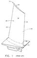
- FIG. 1 illustrates an exemplary gas turbine engine compressor blade 10.
- the compressor blade 10 comprises an airfoil 12, a platform 14, and a shank 16.
- the shank 16 includes a dovetail 18 for being received in a slot of a rotating disk (not shown).
- the airfoil 12 has a leading edge 20, a trailing edge 22, a tip 24, a root 26, a suction side 28, and a pressure side 30.
- Figure 2 shows an enlarged portion of the compressor blade 10.
- Certain areas of the compressor blade 10 are "crack-prone” or particularly subject to crack initiation, for example because of fatigue or damage from foreign object impacts. These areas include the leading edge 20, the trailing edge 22, and the tip 24. Exemplary cracks "C" are shown in these areas of the compressor blade 10. If the compressor blade 10 is left in service, the cracks C will propagate further into the compressor blade 10, eventually rendering it unfit for further service or even causing component failure.
- FIG. 3 shows a compressor blade 110 which has been treated in accordance with the present invention.
- the compressor blade 110 is substantially similar in construction to the compressor blade 10 and includes leading edge 120, trailing edge 122, and tip 124.
- the compressor blade 110 incorporates thin treated zones therein. Within each treated zone, the material of the compressor blade 110 is in a condition of residual compressive stress throughout its thickness.
- a first treated zone 32 extends in a generally radial direction at a first offset distance D1 from the leading edge 120.
- a second treated zone 34 extends in a generally chordwise direction at a second offset distance D2 from the tip 124.
- a third treated zone 36 extends in a generally radial direction at a third offset distance D3 from the trailing edge 122.
- the treated zones 32, 34, and 36 are depicted as straight lines.
- the offset distances D1, D2, D3 will vary with the particular application but may generally be selected small enough to stop a crack before it exceeds the maximum length allowable in service, and large enough that the treated zone can be positioned in a reproducible manner (i.e. away from highly curved features).
- the offset distances D1, D2, D3 are also preferably selected to place the treated zones outside any areas which are aerodynamically sensitive to dimensional changes.
- the offset distance D1 may be about 0.25 mm (0.01 in.) to about 1.3 mm (0.05 in.)
- the treated zones 32, 34, and 36 each have a width "W" which is selected to be wide enough to effectively stop crack propagation while minimizing the number of burnishing or peening passes required.
- the width W may be about 0.13 mm (.005 in.) to about .25 mm (0.01 in.)
- the lengths of the treated zones D1, D2, and D3, denoted L1, L2, and L3, respectively, may be substantially greater than the width W in order to simplify the treatment process.
- a compressor blade 210 may include a treated zone 132 having a shape comprising a series of angled segments or "chevrons".
- the treated zone could also comprise a matrix of densely spaced point or dots.
- One or more additional treated zones of residual compressive stress may be applied to the compressor blade 110 to further reduce crack propagation.
- a supplemental treated zone 38 (see Figure 3 ) extends in a generally radial direction at a supplemental offset distance D4 from the leading edge 120, which is greater that the first offset distance D1.
- the length-to-width ratio of this supplemental treated zone 38 is similar to that of the treated zones described above. This stops the growth of any cracks which may extend past the first treated zone 36.
- further treated zones could be applied behind the supplemental treated zone 38.
- the zones of residual compressive stress may be applied by a number of methods. Examples of known suitable methods include laser shock peening (LSP), pinch peening, shot peening, low plasticity burnishing (LPB), or the use of a textured forming die.
- LSP laser shock peening
- PPB low plasticity burnishing
- One preferred method is low plasticity burnishing, in which a normal force is applied to the compressor blade 110 using a stylus of a known type (not shown). The stylus is translated along the surface of the compressor blade 110 form the intended treated zone of residual compressive stress.
- the amount of cold-working applied to the compressor blade 110 during this process is of relatively little concern given the anticipated operating conditions.
- the compressor blade 110 will be subjected to fatigue and damage that tends to cause cracking.
- the cracks initiate in "crack-prone" areas which may be relatively thin, which are exposed to debris impact, or which contain edges or geometric features that cause stress risers. Examples of such crack-prone areas include the leading edge 120, tip 124, and the trailing edge 122 as discussed above. Unchecked, these cracks would grow and extend further into the compressor blade 110, until eventually the compressor blade failed in service or could not be economically repaired.
- the treatment described in this application may be used with newly made components. However, there is also significant repair activity on components such as compressor blades.
- the methods described in this application can enhance the performance of repaired blades. Repaired blades typically have their dimensions restored by welding, which often has inferior fatigue behavior as compared to the original components. By applying one or more treated zones to a repaired component as described herein, their fatigue and life resistance to crack propagation can be enhanced.
Landscapes
- Engineering & Computer Science (AREA)
- Mechanical Engineering (AREA)
- General Engineering & Computer Science (AREA)
- Chemical & Material Sciences (AREA)
- Materials Engineering (AREA)
- Structures Of Non-Positive Displacement Pumps (AREA)
- Turbine Rotor Nozzle Sealing (AREA)
Claims (9)
- Metallische Schaufelfläche (10) für einen Gasturbinenmotor, der durch mindestens eine Außenkante (20, 22, 24) begrenzt ist, wobei die Schaufelfläche (10) umfasst:eine längliche erste behandelte Zone und eine ergänzende behandelte Zone, wobei die erste behandelte Zone einen ersten Versatz von der Außenkante (20, 22, 24) hat und die ergänzende behandelte Zone im Allgemeinen parallel mit einem ergänzenden Versatz, der größer als der erste Versatz ist, zur Außenkante (20, 22, 24) angeordnet ist, wobei die gesamte Dicke der Komponente (10) innerhalb der ersten und ergänzenden behandelten Zonen sich in einem Zustand von Restdruckspannung befindet, so dass dem Risswachstum vorn der Außenkante (20, 22, 24) widerstanden wird; undeine unbehandelte Zone, die zwischen der ersten und der ergänzenden Zone angeordnet ist.
- Metallische Schaufelfläche (10) nach Anspruch 1, wobei die erste behandelte Zone im Allegemeinen parallel zur Außenkante (20, 22, 24) angeordnet ist und eine Länge in einer Richtung hat, die im Allgemeinen parallel zur Außenkante (20, 22, 24) hat, die im Allgemeinen größer als ihre Breite ist.
- Metallische Schaufelfläche (10) nach Anspruch 2, wobei die Breite etwa 0,13 mm bis etwa 0,25 mm beträgt.
- Metallische Schaufelfläche (10) nach Anspruch 1, wobei der Versatz etwa 0,25 mm bis etwa 1,3 mm beträgt.
- Verfahren zum Reduzieren der Rissausbreitung in metallischen Schaufelflächen, umfassend:Bereitstellen einer metallischen Schaufelfläche (10), die durch mindestens eine Außenkante (20, 22, 24) begrenzt ist, wobei die Schaufelfläche (10) mindestens einen rissanfälligen Bereich umfasst, der teilweise durch die Außenkante (20, 22, 24) begrenzt ist;Anwenden von Druck auf die Schaufelfläche (10) in den länglichen ersten und ergänzenden behandelten Zonen derart, dass die gesamte Dicke der Schaufelfläche (10) innerhalb der behandelten Zonen in einem Zustand von restlicher Druckbeanspruchung gelassen wird, derart dass Risse daran gehindert werden, sich aus der rissanfälligen Zone heraus auszubreiten, wobei die erste behandelte Zone gegenüber der Außenkante durch einen Versatz versetzt ist, und eine unbehandelte Zone zwischen der ersten behandelten Zone und der ergänzenden Zone positioniert ist.
- Verfahren nach Anspruch 5, wobei eine Länge der behandelten Zone wesentlich größer als eine Breite der Zone ist.
- Verfahren nach Anspruch 5, wobei eine Länge der ersten behandelten Zone in einer Richtung, die im Allgemeinen parallel zur Außenkante (20, 22, 24) ist, wesentlich größer als eine Breite der ersten behandelten Zone ist.
- Verfahren nach Anspruch 7, wobei die Breite etwa 0,13 mm bis etwa 0,25 mm beträgt.
- Verfahren nach Anspruch 5, wobei der Versatz etwa 0,25 mm bis etwa 1,3 mm beträgt.
Applications Claiming Priority (1)
| Application Number | Priority Date | Filing Date | Title |
|---|---|---|---|
| US10/999,505 US7229253B2 (en) | 2004-11-30 | 2004-11-30 | Fatigue-resistant components and method therefor |
Publications (3)
| Publication Number | Publication Date |
|---|---|
| EP1662092A2 EP1662092A2 (de) | 2006-05-31 |
| EP1662092A3 EP1662092A3 (de) | 2009-12-09 |
| EP1662092B1 true EP1662092B1 (de) | 2014-06-25 |
Family
ID=35734491
Family Applications (1)
| Application Number | Title | Priority Date | Filing Date |
|---|---|---|---|
| EP05257015.7A Expired - Lifetime EP1662092B1 (de) | 2004-11-30 | 2005-11-14 | Ermüdungs-resistente Gasturbinenschaufel und Methode dafür |
Country Status (5)
| Country | Link |
|---|---|
| US (1) | US7229253B2 (de) |
| EP (1) | EP1662092B1 (de) |
| BR (1) | BRPI0505160A (de) |
| CA (1) | CA2527521C (de) |
| SG (1) | SG122936A1 (de) |
Families Citing this family (28)
| Publication number | Priority date | Publication date | Assignee | Title |
|---|---|---|---|---|
| EP1658924A1 (de) * | 2004-11-22 | 2006-05-24 | Siemens Aktiengesellschaft | Bauteil mit einer aufgefüllten Vertiefung |
| US20060280612A1 (en) * | 2005-06-09 | 2006-12-14 | Prevey Paul S Iii | Metallic article with integral end band under compression |
| FR2889669B1 (fr) * | 2005-08-12 | 2007-11-02 | Snecma | Piece metallique traitee par mise en compression de sous couches. procede pour obtenir une telle piece. |
| WO2007055864A2 (en) * | 2005-10-12 | 2007-05-18 | Surface Technology Holdings, Ltd | Improved integrally bladed rotating turbo machinery and method and apparatus for achieving the same |
| KR20080012744A (ko) | 2006-08-03 | 2008-02-12 | 유나이티드 테크놀로지스 코포레이션 | 부식 코팅되는 부품의 코팅전 버니싱 |
| US8079120B2 (en) * | 2006-12-30 | 2011-12-20 | General Electric Company | Method for determining initial burnishing parameters |
| US8051565B2 (en) * | 2006-12-30 | 2011-11-08 | General Electric Company | Method for increasing fatigue notch capability of airfoils |
| ES2343397B1 (es) * | 2008-03-07 | 2011-06-13 | GAMESA INNOVATION & TECHNOLOGY, S.L. | Una pala de aerogenerador. |
| US20090313823A1 (en) * | 2008-06-24 | 2009-12-24 | Todd Jay Rockstroh | Imparting deep compressive residual stresses into a gas turbine engine airfoil peripheral repair weldment |
| US20100061863A1 (en) * | 2008-09-11 | 2010-03-11 | General Electric Company | airfoil and methods of laser shock peening of airfoil |
| US8297935B2 (en) * | 2008-11-18 | 2012-10-30 | Honeywell International Inc. | Turbine blades and methods of forming modified turbine blades and turbine rotors |
| US8852720B2 (en) * | 2009-07-17 | 2014-10-07 | Rolls-Royce Corporation | Substrate features for mitigating stress |
| EP2524069B1 (de) | 2010-01-11 | 2018-03-07 | Rolls-Royce Corporation | Merkmale zur milderung thermischer oder mechanischer spannungen einer umgebungsschutzschicht |
| DE102011007224A1 (de) * | 2011-04-12 | 2012-10-18 | Rolls-Royce Deutschland Ltd & Co Kg | Verfahren und Herstellung eines einstückigen Rotorbereiches und einstückiger Rotorbereich |
| GB201112696D0 (en) | 2011-07-25 | 2011-09-07 | Rolls Royce Plc | A method of treating an aerofoil |
| DE102012001989B4 (de) * | 2012-02-02 | 2018-10-18 | Rolls-Royce Deutschland Ltd & Co Kg | Verfahren zur mechanischen Randzonenverfestigung von Bauteilen |
| US8959767B2 (en) * | 2012-11-21 | 2015-02-24 | United Technologies Corporation | Method of extending life of rotating parts |
| US10273816B2 (en) * | 2013-02-12 | 2019-04-30 | United Technologies Corporation | Wear pad to prevent cracking of fan blade |
| WO2014144152A1 (en) | 2013-03-15 | 2014-09-18 | Rolls-Royce Corporation | Improved coating interface |
| US9523419B2 (en) * | 2013-08-13 | 2016-12-20 | Schaeffler Technologies AG & Co. KG | Pre-stressed torque converter shell |
| FR3009983B1 (fr) * | 2013-08-29 | 2016-02-12 | Snecma | Procede de fabrication d'un bord de renforcement d'aube et bord de renforcement obtenu par ce procede |
| SG10201502975RA (en) * | 2014-06-03 | 2016-01-28 | United Technologies Corp | Systems and methods for pre-stressing blades |
| US20160102554A1 (en) * | 2014-10-08 | 2016-04-14 | Caterpillar Inc. | Inspection and qualification for remanufacturing of compressor wheels |
| US10738616B2 (en) * | 2016-10-11 | 2020-08-11 | General Electric Company | System and method for maintenance of a turbine assembly |
| EP3321381B1 (de) * | 2016-11-11 | 2022-01-26 | Rolls-Royce plc | Behandelte konische artikel und verfahren zur behandlung für einen konischen artikel |
| ES2950768T3 (es) | 2018-05-11 | 2023-10-13 | Carrier Corp | Sistema de detección por resonancia de plasmones de superficie |
| DE102019118549A1 (de) * | 2019-07-09 | 2021-01-14 | Rolls-Royce Deutschland Ltd & Co Kg | Triebwerksbauteil mit Modifikationsbereich zur Beeinflussung einer Rissausbreitung und Herstellungsverfahren |
| CN114293121B (zh) * | 2021-12-30 | 2022-06-24 | 西北工业大学 | 一种薄壁叶片分区域超声冲击强化方法 |
Family Cites Families (13)
| Publication number | Priority date | Publication date | Assignee | Title |
|---|---|---|---|---|
| EP0196447B1 (de) * | 1985-03-15 | 1989-08-09 | BBC Brown Boveri AG | Verfahren zur Erhöhung des Oxydations- und Korrosionswiderstandes eines Bauteils aus einer dispersionsgehärteten Superlegierung durch eine Oberflächenbehandlung |
| US5591009A (en) * | 1995-01-17 | 1997-01-07 | General Electric Company | Laser shock peened gas turbine engine fan blade edges |
| US5569018A (en) * | 1995-03-06 | 1996-10-29 | General Electric Company | Technique to prevent or divert cracks |
| US5735044A (en) * | 1995-12-12 | 1998-04-07 | General Electric Company | Laser shock peening for gas turbine engine weld repair |
| US6551064B1 (en) * | 1996-07-24 | 2003-04-22 | General Electric Company | Laser shock peened gas turbine engine intermetallic parts |
| US5826453A (en) | 1996-12-05 | 1998-10-27 | Lambda Research, Inc. | Burnishing method and apparatus for providing a layer of compressive residual stress in the surface of a workpiece |
| US5988982A (en) * | 1997-09-09 | 1999-11-23 | Lsp Technologies, Inc. | Altering vibration frequencies of workpieces, such as gas turbine engine blades |
| US6144012A (en) * | 1997-11-05 | 2000-11-07 | Lsp Technologies, Inc. | Efficient laser peening |
| US6005219A (en) | 1997-12-18 | 1999-12-21 | General Electric Company | Ripstop laser shock peening |
| US6672838B1 (en) * | 2000-07-27 | 2004-01-06 | General Electric Company | Method for making a metallic article with integral end band under compression |
| US6657160B2 (en) * | 2001-01-25 | 2003-12-02 | The Regents Of The University Of California | Laser peening of components of thin cross-section |
| US6570125B2 (en) * | 2001-08-31 | 2003-05-27 | General Electric Company | Simultaneous offset dual sided laser shock peening with oblique angle laser beams |
| US6969821B2 (en) * | 2003-06-30 | 2005-11-29 | General Electric Company | Airfoil qualification system and method |
-
2004
- 2004-11-30 US US10/999,505 patent/US7229253B2/en not_active Expired - Lifetime
-
2005
- 2005-11-14 EP EP05257015.7A patent/EP1662092B1/de not_active Expired - Lifetime
- 2005-11-17 CA CA2527521A patent/CA2527521C/en not_active Expired - Fee Related
- 2005-11-23 BR BRPI0505160-6A patent/BRPI0505160A/pt not_active Application Discontinuation
- 2005-11-30 SG SG200507700A patent/SG122936A1/en unknown
Also Published As
| Publication number | Publication date |
|---|---|
| EP1662092A3 (de) | 2009-12-09 |
| EP1662092A2 (de) | 2006-05-31 |
| BRPI0505160A (pt) | 2006-07-11 |
| US7229253B2 (en) | 2007-06-12 |
| CA2527521A1 (en) | 2006-05-30 |
| CA2527521C (en) | 2014-06-10 |
| SG122936A1 (en) | 2006-06-29 |
| US20060147311A1 (en) | 2006-07-06 |
Similar Documents
| Publication | Publication Date | Title |
|---|---|---|
| EP1662092B1 (de) | Ermüdungs-resistente Gasturbinenschaufel und Methode dafür | |
| JP5264165B2 (ja) | 翼形部の疲労切欠き性能を高めるための方法及び装置 | |
| EP0794264B1 (de) | Gasturbinenbläserschaufeln mit Laserschock behandelte Kanten | |
| JP4995501B2 (ja) | ショットピーニングを用いたレーザショック誘起翼形部捻りの打ち消し | |
| EP1892374B2 (de) | Verfahren zur Reparatur ummantelter Turbinenlaufschaufeln mit Rissen in der Nähe des äußeren Aussparung der Ummantelung | |
| US7384244B2 (en) | Fatigue-resistant components and method therefor | |
| US20070157447A1 (en) | Method of improving the properties of a repaired component and a component improved thereby | |
| US6520836B2 (en) | Method of forming a trailing edge cutback for a turbine bucket | |
| US20090235526A1 (en) | Method for the manufacture of a welded blisk drum | |
| KR100416012B1 (ko) | 가스터빈엔진부품및가스터빈엔진압축기블레이드 | |
| EP1862643B1 (de) | Verfahren zur Herstellung einer beschichteten Laufschaufel eines Verdichters | |
| EP0558053A1 (de) | Reparaturmethode für Turbinenschaufeln | |
| WO2008130378A2 (en) | Method of mitigating the effects of damage in an article | |
| EP1807237A2 (de) | Schweissabschirmung zum automatischen schweissen von laufrädern und blisks | |
| US6685429B2 (en) | Prestressing of components | |
| EP3321381B1 (de) | Behandelte konische artikel und verfahren zur behandlung für einen konischen artikel | |
| US20100061863A1 (en) | airfoil and methods of laser shock peening of airfoil | |
| JP4974106B2 (ja) | レーザショック誘起翼形部捻りの打ち消し | |
| EP2943656B1 (de) | Verfahren zur herleitung einer begrenzung für ein materialverbesserungsverfahren an einer turbinenschaufel und schaufel für eine gasturbine | |
| US20130183157A1 (en) | Method of surface treatment for dovetail in gas turbine engine fan blade | |
| CA2068240A1 (en) | Parts for and methods of repairing turbine blades |
Legal Events
| Date | Code | Title | Description |
|---|---|---|---|
| PUAI | Public reference made under article 153(3) epc to a published international application that has entered the european phase |
Free format text: ORIGINAL CODE: 0009012 |
|
| AK | Designated contracting states |
Kind code of ref document: A2 Designated state(s): AT BE BG CH CY CZ DE DK EE ES FI FR GB GR HU IE IS IT LI LT LU LV MC NL PL PT RO SE SI SK TR |
|
| AX | Request for extension of the european patent |
Extension state: AL BA HR MK YU |
|
| PUAL | Search report despatched |
Free format text: ORIGINAL CODE: 0009013 |
|
| AK | Designated contracting states |
Kind code of ref document: A3 Designated state(s): AT BE BG CH CY CZ DE DK EE ES FI FR GB GR HU IE IS IT LI LT LU LV MC NL PL PT RO SE SI SK TR |
|
| AX | Request for extension of the european patent |
Extension state: AL BA HR MK YU |
|
| RIC1 | Information provided on ipc code assigned before grant |
Ipc: F01D 5/00 20060101ALI20091105BHEP Ipc: F01D 5/28 20060101AFI20060214BHEP |
|
| 17P | Request for examination filed |
Effective date: 20100609 |
|
| AKX | Designation fees paid |
Designated state(s): DE FR GB IT |
|
| 17Q | First examination report despatched |
Effective date: 20100730 |
|
| GRAP | Despatch of communication of intention to grant a patent |
Free format text: ORIGINAL CODE: EPIDOSNIGR1 |
|
| INTG | Intention to grant announced |
Effective date: 20140304 |
|
| GRAS | Grant fee paid |
Free format text: ORIGINAL CODE: EPIDOSNIGR3 |
|
| GRAA | (expected) grant |
Free format text: ORIGINAL CODE: 0009210 |
|
| AK | Designated contracting states |
Kind code of ref document: B1 Designated state(s): DE FR GB IT |
|
| REG | Reference to a national code |
Ref country code: GB Ref legal event code: FG4D |
|
| REG | Reference to a national code |
Ref country code: DE Ref legal event code: R096 Ref document number: 602005043994 Country of ref document: DE Effective date: 20140807 |
|
| REG | Reference to a national code |
Ref country code: DE Ref legal event code: R097 Ref document number: 602005043994 Country of ref document: DE |
|
| PLBE | No opposition filed within time limit |
Free format text: ORIGINAL CODE: 0009261 |
|
| STAA | Information on the status of an ep patent application or granted ep patent |
Free format text: STATUS: NO OPPOSITION FILED WITHIN TIME LIMIT |
|
| 26N | No opposition filed |
Effective date: 20150326 |
|
| REG | Reference to a national code |
Ref country code: FR Ref legal event code: PLFP Year of fee payment: 11 |
|
| REG | Reference to a national code |
Ref country code: FR Ref legal event code: PLFP Year of fee payment: 12 |
|
| REG | Reference to a national code |
Ref country code: FR Ref legal event code: PLFP Year of fee payment: 13 |
|
| REG | Reference to a national code |
Ref country code: FR Ref legal event code: PLFP Year of fee payment: 14 |
|
| PGFP | Annual fee paid to national office [announced via postgrant information from national office to epo] |
Ref country code: DE Payment date: 20191021 Year of fee payment: 15 |
|
| PGFP | Annual fee paid to national office [announced via postgrant information from national office to epo] |
Ref country code: IT Payment date: 20191021 Year of fee payment: 15 Ref country code: FR Payment date: 20191022 Year of fee payment: 15 |
|
| REG | Reference to a national code |
Ref country code: DE Ref legal event code: R119 Ref document number: 602005043994 Country of ref document: DE |
|
| PG25 | Lapsed in a contracting state [announced via postgrant information from national office to epo] |
Ref country code: IT Free format text: LAPSE BECAUSE OF NON-PAYMENT OF DUE FEES Effective date: 20201114 Ref country code: FR Free format text: LAPSE BECAUSE OF NON-PAYMENT OF DUE FEES Effective date: 20201130 |
|
| PG25 | Lapsed in a contracting state [announced via postgrant information from national office to epo] |
Ref country code: DE Free format text: LAPSE BECAUSE OF NON-PAYMENT OF DUE FEES Effective date: 20210601 |
|
| P01 | Opt-out of the competence of the unified patent court (upc) registered |
Effective date: 20230414 |
|
| PGFP | Annual fee paid to national office [announced via postgrant information from national office to epo] |
Ref country code: GB Payment date: 20241023 Year of fee payment: 20 |
|
| REG | Reference to a national code |
Ref country code: GB Ref legal event code: PE20 Expiry date: 20251113 |