EP1662201A2 - Kachel und Exoskelett-Kachel-Struktur - Google Patents
Kachel und Exoskelett-Kachel-Struktur Download PDFInfo
- Publication number
- EP1662201A2 EP1662201A2 EP05257389A EP05257389A EP1662201A2 EP 1662201 A2 EP1662201 A2 EP 1662201A2 EP 05257389 A EP05257389 A EP 05257389A EP 05257389 A EP05257389 A EP 05257389A EP 1662201 A2 EP1662201 A2 EP 1662201A2
- Authority
- EP
- European Patent Office
- Prior art keywords
- tile
- rib
- tiles
- ribs
- annular
- Prior art date
- Legal status (The legal status is an assumption and is not a legal conclusion. Google has not performed a legal analysis and makes no representation as to the accuracy of the status listed.)
- Granted
Links
Images

Classifications
-
- F—MECHANICAL ENGINEERING; LIGHTING; HEATING; WEAPONS; BLASTING
- F02—COMBUSTION ENGINES; HOT-GAS OR COMBUSTION-PRODUCT ENGINE PLANTS
- F02C—GAS-TURBINE PLANTS; AIR INTAKES FOR JET-PROPULSION PLANTS; CONTROLLING FUEL SUPPLY IN AIR-BREATHING JET-PROPULSION PLANTS
- F02C7/00—Features, components parts, details or accessories, not provided for in, or of interest apart form groups F02C1/00 - F02C6/00; Air intakes for jet-propulsion plants
- F02C7/20—Mounting or supporting of plant; Accommodating heat expansion or creep
-
- F—MECHANICAL ENGINEERING; LIGHTING; HEATING; WEAPONS; BLASTING
- F23—COMBUSTION APPARATUS; COMBUSTION PROCESSES
- F23R—GENERATING COMBUSTION PRODUCTS OF HIGH PRESSURE OR HIGH VELOCITY, e.g. GAS-TURBINE COMBUSTION CHAMBERS
- F23R3/00—Continuous combustion chambers using liquid or gaseous fuel
- F23R3/002—Wall structures
-
- F—MECHANICAL ENGINEERING; LIGHTING; HEATING; WEAPONS; BLASTING
- F23—COMBUSTION APPARATUS; COMBUSTION PROCESSES
- F23M—CASINGS, LININGS, WALLS OR DOORS SPECIALLY ADAPTED FOR COMBUSTION CHAMBERS, e.g. FIREBRIDGES; DEVICES FOR DEFLECTING AIR, FLAMES OR COMBUSTION PRODUCTS IN COMBUSTION CHAMBERS; SAFETY ARRANGEMENTS SPECIALLY ADAPTED FOR COMBUSTION APPARATUS; DETAILS OF COMBUSTION CHAMBERS, NOT OTHERWISE PROVIDED FOR
- F23M5/00—Casings; Linings; Walls
- F23M5/02—Casings; Linings; Walls characterised by the shape of the bricks or blocks used
-
- F—MECHANICAL ENGINEERING; LIGHTING; HEATING; WEAPONS; BLASTING
- F23—COMBUSTION APPARATUS; COMBUSTION PROCESSES
- F23R—GENERATING COMBUSTION PRODUCTS OF HIGH PRESSURE OR HIGH VELOCITY, e.g. GAS-TURBINE COMBUSTION CHAMBERS
- F23R3/00—Continuous combustion chambers using liquid or gaseous fuel
- F23R3/42—Continuous combustion chambers using liquid or gaseous fuel characterised by the arrangement or form of the flame tubes or combustion chambers
- F23R3/50—Combustion chambers comprising an annular flame tube within an annular casing
-
- F—MECHANICAL ENGINEERING; LIGHTING; HEATING; WEAPONS; BLASTING
- F23—COMBUSTION APPARATUS; COMBUSTION PROCESSES
- F23M—CASINGS, LININGS, WALLS OR DOORS SPECIALLY ADAPTED FOR COMBUSTION CHAMBERS, e.g. FIREBRIDGES; DEVICES FOR DEFLECTING AIR, FLAMES OR COMBUSTION PRODUCTS IN COMBUSTION CHAMBERS; SAFETY ARRANGEMENTS SPECIALLY ADAPTED FOR COMBUSTION APPARATUS; DETAILS OF COMBUSTION CHAMBERS, NOT OTHERWISE PROVIDED FOR
- F23M2900/00—Special features of, or arrangements for combustion chambers
- F23M2900/05004—Special materials for walls or lining
-
- F—MECHANICAL ENGINEERING; LIGHTING; HEATING; WEAPONS; BLASTING
- F23—COMBUSTION APPARATUS; COMBUSTION PROCESSES
- F23R—GENERATING COMBUSTION PRODUCTS OF HIGH PRESSURE OR HIGH VELOCITY, e.g. GAS-TURBINE COMBUSTION CHAMBERS
- F23R2900/00—Special features of, or arrangements for continuous combustion chambers; Combustion processes therefor
- F23R2900/00005—Preventing fatigue failures or reducing mechanical stress in gas turbine components
-
- F—MECHANICAL ENGINEERING; LIGHTING; HEATING; WEAPONS; BLASTING
- F23—COMBUSTION APPARATUS; COMBUSTION PROCESSES
- F23R—GENERATING COMBUSTION PRODUCTS OF HIGH PRESSURE OR HIGH VELOCITY, e.g. GAS-TURBINE COMBUSTION CHAMBERS
- F23R2900/00—Special features of, or arrangements for continuous combustion chambers; Combustion processes therefor
- F23R2900/03044—Impingement cooled combustion chamber walls or subassemblies
-
- F—MECHANICAL ENGINEERING; LIGHTING; HEATING; WEAPONS; BLASTING
- F23—COMBUSTION APPARATUS; COMBUSTION PROCESSES
- F23R—GENERATING COMBUSTION PRODUCTS OF HIGH PRESSURE OR HIGH VELOCITY, e.g. GAS-TURBINE COMBUSTION CHAMBERS
- F23R2900/00—Special features of, or arrangements for continuous combustion chambers; Combustion processes therefor
- F23R2900/03045—Convection cooled combustion chamber walls provided with turbolators or means for creating turbulences to increase cooling
Definitions
- the present invention relates to a generally part-annular tile and to an exo-skeleton tile structure, suitable for an annular combustion liner shell to facilitate cooling of the liner shell by axial gas flow along the gap therebetween. It is particularly useful in gas turbines whose combustion chambers have inner and outer liner shells each requiring cooling.
- an existing Alstom gas turbine the GT13E2
- the GT13E2 comprises an engine 10 receiving compressor gas into its plenum 11 in the direction 12. This gas is fed through a burner system 13 and into a combustion chamber 14 at lower pressure than the plenum 11, where it is combined with fuel and ignited.
- the lower pressure in the combustion chamber 14 means that the liner shell, comprising an inner liner shell 15 and an outer liner shell 17, both generally annular, have to withstand the differential pressures.
- the liner shells need to withstand high internal temperatures up to 500°C or higher, and need to provide sufficient resistance to thermally-induced and pressure-induced stresses, creep and buckling failure modes which would otherwise result in an unacceptable component life.
- the shells need to be sufficiently rigid during operation and resistant to flexing during handling, to avoid damage to themselves and to any coatings applied to them. Cooling of the liner shells is usually provided in the form of impingement and/or convection cooling from the cold side of the shell wall. Channels or an annular cooling flow space are provided by an external structure, in the form of an exo-skeleton tile structure.
- a tile structure 16 of generally annular shape covers the inner liner shell 15, and correspondingly a similar tile structure 18 covers the outer liner shell 17.
- U clips 26, welded onto the hot side 20 of the liner shell 17, have integral studs which project through apertures 22 in the tiles 18.
- Nuts and Bellville washers 27 secure the studs in place, and locate the exo-skeleton tile structure over the liner shell 17.
- This exo-skeleton tile structure resists bending in the axial and shear directions but has the disadvantage of having a low resistance to bending about the axially-extending edges of the adjacent tiles.
- FIG. 2 is a series of graphs showing the temperature gradient and the thermal stresses resulting from a given constant thermal loading applied to liner shells of different wall thicknesses.
- the thermal stress is applied to a skin with a 1mm TBC (Thermal Barrier Coating) on a high temperature turbine component which has active cooling.
- the coating is a ceramic type coating commonly containing Yttrium with a bond coat system.
- TBC provides the surface with additional temperature capability, acts as a reflector of radiation to reduce the overall heat flux and provides a small degree of insulation.
- convective cooling using a 1mm rib height a rib is provided on the cold side of the hot liner shell and acts as a turbulator to enhance the cooling convective heat transfer coefficient.
- Delta temperature i.e.
- the purpose of the invention is to mitigate the disadvantages and limitations of the existing exo-skeleton tile structure.
- the present invention accordingly provides a generally part-annular tile with means for connection, in use, to a parallel annular combustion liner shell, such as a gas turbine combustion liner shell, and formed with at least one rib extending circumferentially across the outer surface of the tile and projecting beyond one edge of the tile, such that like tiles may be linked at their edges by the inter-engagement of a projecting rib of one tile with the rib of an adjacent tile, to form a complete, generally annular structure in use, the inter-engagement being such that the ribs of adjacent tiles are relatively slideable circumferentially, to allow thermal expansion and contraction of the annular structure in use, but such as to resist relative bending of the adjacent tiles about their linked edges, to impart rigidity to the structure.
- the tile has a multiplicity of apertures to allow coolant gas to flow through the tile into the gap between the tile and the liner shell, and to impinge on the external surface of the liner shell. It is also preferred that the tile has a strip of different radius at one of its edges, so that the opposite edge of an adjacent like tile can overlap that strip to allow the tiles to present a generally continuous annular surface.
- the at least one rib that extends circumferentially across the outer surface of the tile and projects beyond one edge of the tile may have at the opposite end a socket for slidingly receiving the projecting rib of an adjacent like tile to form said inter-engagement, the socket providing a radial reaction force for preventing relative bending of the tiles.
- This socket may comprise a further, parallel rib to one side of the end of the main rib, and a socket top cover bridging the parallel ribs.
- the socket may extend circumferentially over between 1/5 and 1/2 of the width of the tile, preferably between 1/4 and 1/3 of the width of the tile.
- the rib is of rectangular section with one edge connected to the tile, the rib projecting radially from the tile normal to its surface.
- connection means between the tile and the liner shell may comprise apertures through the tiles for co-operating with studs projecting radially from the liner shell.
- the tile should be formed of high strength weldable metal alloy capable of withstanding 500°C, for example, an indium cobalt alloy such as Inco 617 (Trade Mark).
- the rib or ribs is or are connected to the tile by brazing or TIG-type welding to transmit shear loading.
- each tile may comprise means for temporarily fixing together a rib of one tile with the socket of an adjacent tile against circumferential sliding movement, the rib and socket of each tile being formed to receive the fixing means.
- the fixing means may comprise pins, and in this case the ribs are formed to accommodate pins extending axially of the tile.
- the tile may have an angular extent around the circumference of the liner shell of from 5 degrees to 15 degrees, preferably 10 degrees to 15 degrees.
- the invention provides a generally annular exo-skeleton tile structure for an annular combustion liner shell to facilitate cooling of the liner shell by axial gas flow along the gap therebetween, comprising part-annular tiles, the tiles being linked together edgewise by the inter-engagement of external circumferentially-extending ribs on the outer surfaces of the tiles, the inter-engagement being such that the ribs of adjacent tiles are relatively slideable circumferentially, to allow thermal expansion and contraction of the annular structure in use, but such as to resist relative bending of the adjacent tiles about their linked edges, to impart rigidity to the structure; the tiles having means for connection to the underlying liner shell in use.
- the invention provides a gas turbine structure comprising a combustion chamber whose liner shell has an exo-skeleton tile structure.
- the invention provides a method of forming a generally annular exo-skeleton tile structure over an annular liner shell, comprising connecting a plurality of part-annular tiles to the liner shell with their edges linked together and their ribs inter-engaging to prevent bending along the edges.
- assembly can be aided by pinning the ribs of adjacent tiles together during assembly, the pins being removed after assembly.
- the above-mentioned socket top cover can be connected after the ribs have been inter-engaged.
- Wear coatings such as Stellite 6 (Trade Mark) can be applied to the tiles, or to the liner shells, or both, including the ribs.
- the rib in each tile capable of inter-engaging the rib of an adjacent tile, provides circumferential stiffening and overcomes the previous problem of bending in the circumferential direction.
- a further advantage of the invention is that the tuning of resonant vibration modes becomes possible by optimising the number and location of the stiffening ribs.
- Damping of vibrational modes is facilitated by friction inherent in the sliding joints between inter-engaging ribs.
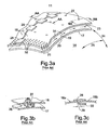
- the tile 18, formed of Inco 617 and resistant to at least 500°C has two strengthening ribs 40 extending circumferentially, and at least one rib 45 extending axially, the ribs being fastened to the tile surface by brazing or TIG type welding, so as to be capable of transmitting shear loading.
- Each rib has a rectangular section (although other sections could instead be selected - say circular) and extends normally from the cold surface of the tile 18.
- the tile presents a generally annular surface, whose radius varies along the axis, i.e. the diameter of the exo-skeleton tile structure varies along the length of the engine.
- the tile 18 subtends, in this example, an angle of approximately 15° in the circumferential direction, and the complete structure would therefore require 24 inter-engaging tiles joined edgewise.
- the range of angles for each tile could be between say 5° and 15°, preferably 10° to 15°; segments subtending much more than 15° would begin to develop significant Meridional stress issues.
- Each circumferential rib 40 has at one end a projecting portion 41 beyond the edge of the tile. This engages in a socket 42 formed by the opposite end of the rib 40 of an adjacent tile.
- the socket is formed by one end 41 of the rib 40, by a parallel and adjacent short rib 43, and by a socket top cover in the form of a rectangular plate 44 bridging the ribs 41 and 43.
- the socket extends circumferentially over between 1/5 and 1 ⁇ 2, and preferably between 1 ⁇ 4 and 1/3 of the width of the tile 18.
- the rib 40 is free to slide in the circumferential direction 46 within the socket.
- the socket top cover 44 is separated from the inner surface of the tile 18 by a gap slightly greater in the radial direction than the height of the rib 40 which it accommodates, so as to provide a sliding clearance 47 which is small enough to limit bending by virtue of the contact between the rib 40 and the top cover 44 and the tile skin 18.
- the top cover and the tile provide radial reaction forces acting on the rib 40 to prevent or at least to limit the bending motion, i.e. the ability of adjacent tiles to bend along their adjacent edge.
- a total clearance of say 2% of the socket engagement length would permit an angular miss-alignment of 1.145° tile to tile. The actual angle tolerable may be determined by experiment. The lower limit of the clearance would be determined by the incidence of binding.
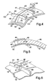
- each tile 18 has the features of the conventional tile shown in Figure 3, including the apertures 22 for receiving studs welded to the liner shell 17.
- the multiplicity of small apertures 32 for impingement flow is illustrated in Figure 4.
- the sockets and the projecting portions 41 of the ribs 40 are formed with apertures for accommodating the pair of pins 48 which are assembled by pushing them axially through the apertures to lock the tile joints.
- This provides extra rigidity during handling pre-assembly, but the pins must be removed after assembly and before use, to allow for thermal circumferential expansion at the joints (the extra rigidity during handling being provided to protect the TBC coating system from excessive handling damage caused by deflections to the inner shell liner prior to installation).
- the exo-skeleton tile structure is assembled over the liner shell by locating each successive tile 18 over the studs and inter-engaging the edges of adjacent tiles, with the projecting portions of the ribs sliding into the sockets. The nuts and washers are then secured over the studs. This process may be facilitated by leaving the sockets open at the top until after assembly, i.e. by brazing or welding the top covers 44 once the tiles are in place.
- the tuning of resonant vibration modes is possible by optimisation of the stiffening ribs 41 and 45, and damping is facilitated by friction in the sliding joints between the ribs and the sockets.
- exo-skeleton tile structure facilitates the use of still thinner liner shell structures in gas turbines, and this leads to consequential improvements in the thermal low cycle fatigue (LCF) component life. It further allows for enhanced tuning of problematic vibration modes by optimising rib stiffness, and allows for mechanical damping by energy absorption due to friction in the sliding cavities of the sockets.
- LCD thermal low cycle fatigue
- the wear coatings applied to the tiles (or to the liner shells or both) including the ribs are selected in accordance with the outcome of tribology tests, and one example of a suitable coating is Stellite 6.
Landscapes
- Engineering & Computer Science (AREA)
- Chemical & Material Sciences (AREA)
- Combustion & Propulsion (AREA)
- Mechanical Engineering (AREA)
- General Engineering & Computer Science (AREA)
- Turbine Rotor Nozzle Sealing (AREA)
- Finishing Walls (AREA)
Applications Claiming Priority (1)
| Application Number | Priority Date | Filing Date | Title |
|---|---|---|---|
| GB0426235A GB2420614B (en) | 2004-11-30 | 2004-11-30 | Tile and exo-skeleton tile structure |
Publications (3)
| Publication Number | Publication Date |
|---|---|
| EP1662201A2 true EP1662201A2 (de) | 2006-05-31 |
| EP1662201A3 EP1662201A3 (de) | 2008-05-21 |
| EP1662201B1 EP1662201B1 (de) | 2016-02-17 |
Family
ID=33561558
Family Applications (1)
| Application Number | Title | Priority Date | Filing Date |
|---|---|---|---|
| EP05257389.6A Expired - Lifetime EP1662201B1 (de) | 2004-11-30 | 2005-11-30 | Kachel und Exoskelett-Kachel-Struktur |
Country Status (3)
| Country | Link |
|---|---|
| US (1) | US7942004B2 (de) |
| EP (1) | EP1662201B1 (de) |
| GB (1) | GB2420614B (de) |
Cited By (4)
| Publication number | Priority date | Publication date | Assignee | Title |
|---|---|---|---|---|
| CH699309A1 (de) * | 2008-08-14 | 2010-02-15 | Alstom Technology Ltd | Thermische maschine mit luftgekühlter, ringförmiger brennkammer. |
| EP2281789A1 (de) | 2009-06-30 | 2011-02-09 | Alstom Technology Ltd | Schlickerformulierung zur Herstellung von thermischen Schutzschichten |
| WO2014099091A3 (en) * | 2012-10-01 | 2014-08-28 | Alstom Technology Ltd. | Thermally free liner retention mechanism |
| GB2545459A (en) * | 2015-12-17 | 2017-06-21 | Rolls Royce Plc | A combustion chamber |
Families Citing this family (31)
| Publication number | Priority date | Publication date | Assignee | Title |
|---|---|---|---|---|
| MY161317A (en) * | 2008-02-20 | 2017-04-14 | General Electric Technology Gmbh | Gas turbine |
| US8646276B2 (en) * | 2009-11-11 | 2014-02-11 | General Electric Company | Combustor assembly for a turbine engine with enhanced cooling |
| FR2953907B1 (fr) * | 2009-12-11 | 2012-11-02 | Snecma | Chambre de combustion pour turbomachine |
| US20120082541A1 (en) * | 2010-09-30 | 2012-04-05 | Enzo Macchia | Gas turbine engine casing |
| DE102011076473A1 (de) * | 2011-05-25 | 2012-11-29 | Rolls-Royce Deutschland Ltd & Co Kg | Segmentbauteil aus Hochtemperaturgussmaterial für eine Ringbrennkammer, Ringbrennkammer für ein Flugzeugtriebwerk, Flugzeugtriebwerk und Verfahren zur Herstellung einer Ringbrennkammer |
| US9229172B2 (en) | 2011-09-12 | 2016-01-05 | Commscope Technologies Llc | Bend-limited flexible optical interconnect device for signal distribution |
| US9417418B2 (en) | 2011-09-12 | 2016-08-16 | Commscope Technologies Llc | Flexible lensed optical interconnect device for signal distribution |
| CN103917904A (zh) | 2011-10-07 | 2014-07-09 | Adc电信公司 | 光纤盒、系统和方法 |
| US9498850B2 (en) | 2012-03-27 | 2016-11-22 | Pratt & Whitney Canada Corp. | Structural case for aircraft gas turbine engine |
| AU2013323664B2 (en) | 2012-09-28 | 2017-12-07 | Adc Telecommunications, Inc. | Manufacture and testing of fiber optic cassette |
| ES2792122T3 (es) | 2012-09-28 | 2020-11-10 | Commscope Connectivity Uk Ltd | Casete de fibra óptica |
| US9146374B2 (en) | 2012-09-28 | 2015-09-29 | Adc Telecommunications, Inc. | Rapid deployment packaging for optical fiber |
| US9223094B2 (en) | 2012-10-05 | 2015-12-29 | Tyco Electronics Nederland Bv | Flexible optical circuit, cassettes, and methods |
| CA2904200A1 (en) | 2013-03-05 | 2014-09-12 | Rolls-Royce Corporation | Dual-wall impingement, convection, effusion combustor tile |
| US9435975B2 (en) | 2013-03-15 | 2016-09-06 | Commscope Technologies Llc | Modular high density telecommunications frame and chassis system |
| WO2014149108A1 (en) | 2013-03-15 | 2014-09-25 | Graves Charles B | Shell and tiled liner arrangement for a combustor |
| US9528440B2 (en) | 2013-05-31 | 2016-12-27 | General Electric Company | Gas turbine exhaust diffuser strut fairing having flow manifold and suction side openings |
| WO2015050879A1 (en) | 2013-10-04 | 2015-04-09 | United Technologies Corporation | Heat shield panels with overlap joints for a turbine engine combustor |
| CN103557536B (zh) * | 2013-11-14 | 2016-01-06 | 深圳智慧能源技术有限公司 | 陶瓷热屏蔽片及耐热结构 |
| US9612017B2 (en) | 2014-06-05 | 2017-04-04 | Rolls-Royce North American Technologies, Inc. | Combustor with tiled liner |
| GB201501817D0 (en) * | 2015-02-04 | 2015-03-18 | Rolls Royce Plc | A combustion chamber and a combustion chamber segment |
| DE102016213810A1 (de) * | 2016-07-27 | 2018-02-01 | MTU Aero Engines AG | Verkleidungselement für ein Turbinenzwischengehäuse |
| GB201613299D0 (en) * | 2016-08-02 | 2016-09-14 | Rolls Royce Plc | A method of assembling an annular combustion chamber assembly |
| EP3510432A1 (de) | 2016-09-08 | 2019-07-17 | CommScope Connectivity Belgium BVBA | Telekommunikationsverteilungselemente |
| US10480351B2 (en) * | 2017-05-01 | 2019-11-19 | General Electric Company | Segmented liner |
| EP3692404A4 (de) | 2017-10-02 | 2021-06-16 | Commscope Technologies LLC | Faseroptische schaltung und herstellungsverfahren |
| GB201800375D0 (en) * | 2018-01-10 | 2018-02-21 | Rolls Royce Plc | A test specimen for a gas turbine engine |
| US11047575B2 (en) * | 2019-04-15 | 2021-06-29 | Raytheon Technologies Corporation | Combustor heat shield panel |
| EP4127799B1 (de) | 2020-03-31 | 2025-11-19 | CommScope Technologies LLC | Glasfaserkabelverwaltungssysteme |
| CN116928695A (zh) * | 2022-03-31 | 2023-10-24 | 通用电气公司 | 用于燃烧器的环形圆顶组件 |
| US20230266005A1 (en) * | 2022-05-02 | 2023-08-24 | MAPNA Turbine Engineering and manufacturing Company | Double-skin liner for a gas turbine |
Family Cites Families (27)
| Publication number | Priority date | Publication date | Assignee | Title |
|---|---|---|---|---|
| US2544538A (en) * | 1948-12-01 | 1951-03-06 | Wright Aeronautical Corp | Liner for hot gas chambers |
| CH344262A (de) * | 1955-06-16 | 1960-01-31 | Jan Dr Jerie | Verbrennungskammer mit gekühlter Innenwand |
| US4614082A (en) * | 1972-12-19 | 1986-09-30 | General Electric Company | Combustion chamber construction |
| US3965066A (en) * | 1974-03-15 | 1976-06-22 | General Electric Company | Combustor-turbine nozzle interconnection |
| US4158949A (en) * | 1977-11-25 | 1979-06-26 | General Motors Corporation | Segmented annular combustor |
| US4378961A (en) * | 1979-01-10 | 1983-04-05 | United Technologies Corporation | Case assembly for supporting stator vanes |
| CH643050A5 (de) * | 1979-10-01 | 1984-05-15 | Proizv Ob Nevsky Z Im V I | Gasturbinentriebwerk mit ringbrennkammer. |
| US4861229A (en) * | 1987-11-16 | 1989-08-29 | Williams International Corporation | Ceramic-matrix composite nozzle assembly for a turbine engine |
| US5025622A (en) * | 1988-08-26 | 1991-06-25 | Sol-3- Resources, Inc. | Annular vortex combustor |
| FR2644209B1 (fr) * | 1989-03-08 | 1991-05-03 | Snecma | Chemise de protection thermique pour canal chaud de turboreacteur |
| US5144795A (en) * | 1991-05-14 | 1992-09-08 | The United States Of America As Represented By The Secretary Of The Air Force | Fluid cooled hot duct liner structure |
| US5363643A (en) * | 1993-02-08 | 1994-11-15 | General Electric Company | Segmented combustor |
| DE4309200A1 (de) * | 1993-03-22 | 1994-09-29 | Abb Management Ag | Vorrichtung zur Einhängung und Entfernung thermisch hoch belasteter Teile in Turbinenanlagen |
| FR2710968B1 (fr) * | 1993-10-06 | 1995-11-03 | Snecma | Chambre de combustion à double paroi. |
| FR2723177B1 (fr) * | 1994-07-27 | 1996-09-06 | Snecma | Chambre de combustion comportant une double paroi |
| US5461866A (en) * | 1994-12-15 | 1995-10-31 | United Technologies Corporation | Gas turbine engine combustion liner float wall cooling arrangement |
| GB2298267B (en) * | 1995-02-23 | 1999-01-13 | Rolls Royce Plc | An arrangement of heat resistant tiles for a gas turbine engine combustor |
| US5560198A (en) * | 1995-05-25 | 1996-10-01 | United Technologies Corporation | Cooled gas turbine engine augmentor fingerseal assembly |
| FR2777634B1 (fr) * | 1998-04-16 | 2000-05-19 | Snecma | Separateur pour chambre de combustion a deux tetes |
| US6079199A (en) * | 1998-06-03 | 2000-06-27 | Pratt & Whitney Canada Inc. | Double pass air impingement and air film cooling for gas turbine combustor walls |
| US6098397A (en) * | 1998-06-08 | 2000-08-08 | Caterpillar Inc. | Combustor for a low-emissions gas turbine engine |
| US6347508B1 (en) * | 2000-03-22 | 2002-02-19 | Allison Advanced Development Company | Combustor liner support and seal assembly |
| US6962025B1 (en) * | 2001-05-29 | 2005-11-08 | H.B. Fuller Licensing & Financing, Inc. | Metal plasma surface-modified thermal barrier channel |
| JP3600912B2 (ja) * | 2001-09-12 | 2004-12-15 | 川崎重工業株式会社 | 燃焼器ライナのシール構造 |
| JP3840556B2 (ja) * | 2002-08-22 | 2006-11-01 | 川崎重工業株式会社 | 燃焼器ライナのシール構造 |
| US6807803B2 (en) * | 2002-12-06 | 2004-10-26 | General Electric Company | Gas turbine exhaust diffuser |
| US6931855B2 (en) * | 2003-05-12 | 2005-08-23 | Siemens Westinghouse Power Corporation | Attachment system for coupling combustor liners to a carrier of a turbine combustor |
-
2004
- 2004-11-30 GB GB0426235A patent/GB2420614B/en not_active Expired - Lifetime
-
2005
- 2005-11-30 EP EP05257389.6A patent/EP1662201B1/de not_active Expired - Lifetime
- 2005-11-30 US US11/290,998 patent/US7942004B2/en active Active
Cited By (11)
| Publication number | Priority date | Publication date | Assignee | Title |
|---|---|---|---|---|
| CH699309A1 (de) * | 2008-08-14 | 2010-02-15 | Alstom Technology Ltd | Thermische maschine mit luftgekühlter, ringförmiger brennkammer. |
| EP2154431A3 (de) * | 2008-08-14 | 2010-08-04 | Alstom Technology Ltd | Thermische Maschine |
| US8434313B2 (en) | 2008-08-14 | 2013-05-07 | Alstom Technology Ltd. | Thermal machine |
| EP2281789A1 (de) | 2009-06-30 | 2011-02-09 | Alstom Technology Ltd | Schlickerformulierung zur Herstellung von thermischen Schutzschichten |
| US8758502B2 (en) | 2009-06-30 | 2014-06-24 | Alstom Technology Ltd. | Slurry formulation for the production of thermal barrier coatings |
| WO2014099091A3 (en) * | 2012-10-01 | 2014-08-28 | Alstom Technology Ltd. | Thermally free liner retention mechanism |
| CN104685296A (zh) * | 2012-10-01 | 2015-06-03 | 阿尔斯通技术有限公司 | 热自由衬套固持机构 |
| CN104685296B (zh) * | 2012-10-01 | 2017-07-21 | 通用电器技术有限公司 | 热自由衬套固持机构 |
| GB2545459A (en) * | 2015-12-17 | 2017-06-21 | Rolls Royce Plc | A combustion chamber |
| US10533746B2 (en) | 2015-12-17 | 2020-01-14 | Rolls-Royce Plc | Combustion chamber with fences for directing cooling flow |
| GB2545459B (en) * | 2015-12-17 | 2020-05-06 | Rolls Royce Plc | A combustion chamber |
Also Published As
| Publication number | Publication date |
|---|---|
| US20060179770A1 (en) | 2006-08-17 |
| GB0426235D0 (en) | 2004-12-29 |
| EP1662201B1 (de) | 2016-02-17 |
| GB2420614B (en) | 2009-06-03 |
| EP1662201A3 (de) | 2008-05-21 |
| GB2420614A (en) | 2006-05-31 |
| US7942004B2 (en) | 2011-05-17 |
Similar Documents
| Publication | Publication Date | Title |
|---|---|---|
| US7942004B2 (en) | Tile and exo-skeleton tile structure | |
| US11111823B2 (en) | Turbine ring assembly with inter-sector sealing | |
| EP0994304B1 (de) | Wärmebewegliche Auskleidung | |
| EP1046002B1 (de) | Ineinanderschiebbare brückendichtung | |
| EP3327254B1 (de) | Dichtungsanordnung für gasturbinenmotorkomponenten | |
| EP2543826A2 (de) | Verbunddeckband | |
| US7901186B2 (en) | Seal assembly | |
| US8511982B2 (en) | Compressor vane diaphragm | |
| US8511972B2 (en) | Seal member for use in a seal system between a transition duct exit section and a turbine inlet in a gas turbine engine | |
| CN100482928C (zh) | 密封装置 | |
| US20050082768A1 (en) | Seal device | |
| JP6141871B2 (ja) | 高温気体膨張装置の入口ケーシング組立体及び方法 | |
| US20090191053A1 (en) | Diaphragm and blades for turbomachinery | |
| US20160245108A1 (en) | Apparatus and methods for sealing components in gas turbine engines | |
| EP2481988B1 (de) | Brennkammerwandstütze und Dichtungsanordnung | |
| KR20040100994A (ko) | 연소실 단부벽과 연소실 측벽 사이에 유연한 연결이형성되어 있는 연소실 | |
| US20030031557A1 (en) | Stay sector of stator shroud of the high-pressure turbine of a gas turbine engine with clearance control | |
| US20180112549A1 (en) | Overhanging seal assembly for a gas turbine | |
| US5238365A (en) | Assembly for thermal shielding of low pressure turbine | |
| EP1921277A2 (de) | Mechanischer Träger für einen Keramik-Schaufelring einer Gasturbine | |
| EP3090138B1 (de) | Hitzeschilder für luftdichtungen | |
| JP2007513281A (ja) | 燃焼器壁とノズルプラットフォームとの間の褶動ジョイント | |
| EP3270061B1 (de) | Montage für eine kassettenanordnung einer brennkammersauskleidung | |
| US9476322B2 (en) | Combustor transition duct assembly with inner liner | |
| EP0522795B1 (de) | Hitzeschild |
Legal Events
| Date | Code | Title | Description |
|---|---|---|---|
| PUAI | Public reference made under article 153(3) epc to a published international application that has entered the european phase |
Free format text: ORIGINAL CODE: 0009012 |
|
| AK | Designated contracting states |
Kind code of ref document: A2 Designated state(s): AT BE BG CH CY CZ DE DK EE ES FI FR GB GR HU IE IS IT LI LT LU LV MC NL PL PT RO SE SI SK TR |
|
| AX | Request for extension of the european patent |
Extension state: AL BA HR MK YU |
|
| PUAL | Search report despatched |
Free format text: ORIGINAL CODE: 0009013 |
|
| AK | Designated contracting states |
Kind code of ref document: A3 Designated state(s): AT BE BG CH CY CZ DE DK EE ES FI FR GB GR HU IE IS IT LI LT LU LV MC NL PL PT RO SE SI SK TR |
|
| AX | Request for extension of the european patent |
Extension state: AL BA HR MK YU |
|
| 17P | Request for examination filed |
Effective date: 20080605 |
|
| AKX | Designation fees paid |
Designated state(s): AT BE BG CH CY CZ DE DK EE ES FI FR GB GR HU IE IS IT LI LT LU LV MC NL PL PT RO SE SI SK TR |
|
| 17Q | First examination report despatched |
Effective date: 20141212 |
|
| GRAP | Despatch of communication of intention to grant a patent |
Free format text: ORIGINAL CODE: EPIDOSNIGR1 |
|
| INTG | Intention to grant announced |
Effective date: 20150811 |
|
| GRAS | Grant fee paid |
Free format text: ORIGINAL CODE: EPIDOSNIGR3 |
|
| GRAA | (expected) grant |
Free format text: ORIGINAL CODE: 0009210 |
|
| INTG | Intention to grant announced |
Effective date: 20151215 |
|
| AK | Designated contracting states |
Kind code of ref document: B1 Designated state(s): AT BE BG CH CY CZ DE DK EE ES FI FR GB GR HU IE IS IT LI LT LU LV MC NL PL PT RO SE SI SK TR |
|
| REG | Reference to a national code |
Ref country code: GB Ref legal event code: FG4D |
|
| REG | Reference to a national code |
Ref country code: DE Ref legal event code: R081 Ref document number: 602005048451 Country of ref document: DE Owner name: GENERAL ELECTRIC TECHNOLOGY GMBH, CH Free format text: FORMER OWNER: ALSTOM TECHNOLOGY LTD., BADEN, CH Ref country code: DE Ref legal event code: R081 Ref document number: 602005048451 Country of ref document: DE Owner name: ANSALDO ENERGIA SWITZERLAND AG, CH Free format text: FORMER OWNER: ALSTOM TECHNOLOGY LTD., BADEN, CH |
|
| REG | Reference to a national code |
Ref country code: CH Ref legal event code: EP |
|
| REG | Reference to a national code |
Ref country code: IE Ref legal event code: FG4D |
|
| REG | Reference to a national code |
Ref country code: AT Ref legal event code: REF Ref document number: 775829 Country of ref document: AT Kind code of ref document: T Effective date: 20160315 |
|
| REG | Reference to a national code |
Ref country code: DE Ref legal event code: R096 Ref document number: 602005048451 Country of ref document: DE |
|
| REG | Reference to a national code |
Ref country code: NL Ref legal event code: MP Effective date: 20160217 |
|
| REG | Reference to a national code |
Ref country code: LT Ref legal event code: MG4D |
|
| REG | Reference to a national code |
Ref country code: AT Ref legal event code: MK05 Ref document number: 775829 Country of ref document: AT Kind code of ref document: T Effective date: 20160217 |
|
| PG25 | Lapsed in a contracting state [announced via postgrant information from national office to epo] |
Ref country code: ES Free format text: LAPSE BECAUSE OF FAILURE TO SUBMIT A TRANSLATION OF THE DESCRIPTION OR TO PAY THE FEE WITHIN THE PRESCRIBED TIME-LIMIT Effective date: 20160217 Ref country code: FI Free format text: LAPSE BECAUSE OF FAILURE TO SUBMIT A TRANSLATION OF THE DESCRIPTION OR TO PAY THE FEE WITHIN THE PRESCRIBED TIME-LIMIT Effective date: 20160217 Ref country code: GR Free format text: LAPSE BECAUSE OF FAILURE TO SUBMIT A TRANSLATION OF THE DESCRIPTION OR TO PAY THE FEE WITHIN THE PRESCRIBED TIME-LIMIT Effective date: 20160518 |
|
| RAP2 | Party data changed (patent owner data changed or rights of a patent transferred) |
Owner name: GENERAL ELECTRIC TECHNOLOGY GMBH |
|
| PG25 | Lapsed in a contracting state [announced via postgrant information from national office to epo] |
Ref country code: LT Free format text: LAPSE BECAUSE OF FAILURE TO SUBMIT A TRANSLATION OF THE DESCRIPTION OR TO PAY THE FEE WITHIN THE PRESCRIBED TIME-LIMIT Effective date: 20160217 Ref country code: SE Free format text: LAPSE BECAUSE OF FAILURE TO SUBMIT A TRANSLATION OF THE DESCRIPTION OR TO PAY THE FEE WITHIN THE PRESCRIBED TIME-LIMIT Effective date: 20160217 Ref country code: AT Free format text: LAPSE BECAUSE OF FAILURE TO SUBMIT A TRANSLATION OF THE DESCRIPTION OR TO PAY THE FEE WITHIN THE PRESCRIBED TIME-LIMIT Effective date: 20160217 Ref country code: PT Free format text: LAPSE BECAUSE OF FAILURE TO SUBMIT A TRANSLATION OF THE DESCRIPTION OR TO PAY THE FEE WITHIN THE PRESCRIBED TIME-LIMIT Effective date: 20160617 Ref country code: PL Free format text: LAPSE BECAUSE OF FAILURE TO SUBMIT A TRANSLATION OF THE DESCRIPTION OR TO PAY THE FEE WITHIN THE PRESCRIBED TIME-LIMIT Effective date: 20160217 Ref country code: NL Free format text: LAPSE BECAUSE OF FAILURE TO SUBMIT A TRANSLATION OF THE DESCRIPTION OR TO PAY THE FEE WITHIN THE PRESCRIBED TIME-LIMIT Effective date: 20160217 Ref country code: LV Free format text: LAPSE BECAUSE OF FAILURE TO SUBMIT A TRANSLATION OF THE DESCRIPTION OR TO PAY THE FEE WITHIN THE PRESCRIBED TIME-LIMIT Effective date: 20160217 |
|
| PG25 | Lapsed in a contracting state [announced via postgrant information from national office to epo] |
Ref country code: EE Free format text: LAPSE BECAUSE OF FAILURE TO SUBMIT A TRANSLATION OF THE DESCRIPTION OR TO PAY THE FEE WITHIN THE PRESCRIBED TIME-LIMIT Effective date: 20160217 Ref country code: DK Free format text: LAPSE BECAUSE OF FAILURE TO SUBMIT A TRANSLATION OF THE DESCRIPTION OR TO PAY THE FEE WITHIN THE PRESCRIBED TIME-LIMIT Effective date: 20160217 |
|
| REG | Reference to a national code |
Ref country code: DE Ref legal event code: R097 Ref document number: 602005048451 Country of ref document: DE |
|
| PG25 | Lapsed in a contracting state [announced via postgrant information from national office to epo] |
Ref country code: RO Free format text: LAPSE BECAUSE OF FAILURE TO SUBMIT A TRANSLATION OF THE DESCRIPTION OR TO PAY THE FEE WITHIN THE PRESCRIBED TIME-LIMIT Effective date: 20160217 Ref country code: SK Free format text: LAPSE BECAUSE OF FAILURE TO SUBMIT A TRANSLATION OF THE DESCRIPTION OR TO PAY THE FEE WITHIN THE PRESCRIBED TIME-LIMIT Effective date: 20160217 Ref country code: CZ Free format text: LAPSE BECAUSE OF FAILURE TO SUBMIT A TRANSLATION OF THE DESCRIPTION OR TO PAY THE FEE WITHIN THE PRESCRIBED TIME-LIMIT Effective date: 20160217 |
|
| PLBE | No opposition filed within time limit |
Free format text: ORIGINAL CODE: 0009261 |
|
| STAA | Information on the status of an ep patent application or granted ep patent |
Free format text: STATUS: NO OPPOSITION FILED WITHIN TIME LIMIT |
|
| PG25 | Lapsed in a contracting state [announced via postgrant information from national office to epo] |
Ref country code: BE Free format text: LAPSE BECAUSE OF FAILURE TO SUBMIT A TRANSLATION OF THE DESCRIPTION OR TO PAY THE FEE WITHIN THE PRESCRIBED TIME-LIMIT Effective date: 20160217 |
|
| 26N | No opposition filed |
Effective date: 20161118 |
|
| PG25 | Lapsed in a contracting state [announced via postgrant information from national office to epo] |
Ref country code: BG Free format text: LAPSE BECAUSE OF FAILURE TO SUBMIT A TRANSLATION OF THE DESCRIPTION OR TO PAY THE FEE WITHIN THE PRESCRIBED TIME-LIMIT Effective date: 20160517 Ref country code: SI Free format text: LAPSE BECAUSE OF FAILURE TO SUBMIT A TRANSLATION OF THE DESCRIPTION OR TO PAY THE FEE WITHIN THE PRESCRIBED TIME-LIMIT Effective date: 20160217 |
|
| REG | Reference to a national code |
Ref country code: DE Ref legal event code: R081 Ref document number: 602005048451 Country of ref document: DE Owner name: GENERAL ELECTRIC TECHNOLOGY GMBH, CH Free format text: FORMER OWNER: ALSTOM TECHNOLOGY LTD., BADEN, CH Ref country code: DE Ref legal event code: R081 Ref document number: 602005048451 Country of ref document: DE Owner name: ANSALDO ENERGIA SWITZERLAND AG, CH Free format text: FORMER OWNER: ALSTOM TECHNOLOGY LTD., BADEN, CH Ref country code: DE Ref legal event code: R082 Ref document number: 602005048451 Country of ref document: DE Representative=s name: DREISS PATENTANWAELTE PARTG MBB, DE |
|
| REG | Reference to a national code |
Ref country code: CH Ref legal event code: PL |
|
| PG25 | Lapsed in a contracting state [announced via postgrant information from national office to epo] |
Ref country code: CH Free format text: LAPSE BECAUSE OF NON-PAYMENT OF DUE FEES Effective date: 20161130 Ref country code: LI Free format text: LAPSE BECAUSE OF NON-PAYMENT OF DUE FEES Effective date: 20161130 |
|
| REG | Reference to a national code |
Ref country code: IE Ref legal event code: MM4A |
|
| REG | Reference to a national code |
Ref country code: FR Ref legal event code: ST Effective date: 20170731 |
|
| PG25 | Lapsed in a contracting state [announced via postgrant information from national office to epo] |
Ref country code: LU Free format text: LAPSE BECAUSE OF NON-PAYMENT OF DUE FEES Effective date: 20161130 |
|
| REG | Reference to a national code |
Ref country code: DE Ref legal event code: R082 Ref document number: 602005048451 Country of ref document: DE Representative=s name: DREISS PATENTANWAELTE PARTG MBB, DE Ref country code: DE Ref legal event code: R081 Ref document number: 602005048451 Country of ref document: DE Owner name: ANSALDO ENERGIA SWITZERLAND AG, CH Free format text: FORMER OWNER: GENERAL ELECTRIC TECHNOLOGY GMBH, BADEN, CH |
|
| PG25 | Lapsed in a contracting state [announced via postgrant information from national office to epo] |
Ref country code: FR Free format text: LAPSE BECAUSE OF NON-PAYMENT OF DUE FEES Effective date: 20161130 |
|
| REG | Reference to a national code |
Ref country code: GB Ref legal event code: 732E Free format text: REGISTERED BETWEEN 20171102 AND 20171108 |
|
| PG25 | Lapsed in a contracting state [announced via postgrant information from national office to epo] |
Ref country code: IE Free format text: LAPSE BECAUSE OF NON-PAYMENT OF DUE FEES Effective date: 20161130 |
|
| PG25 | Lapsed in a contracting state [announced via postgrant information from national office to epo] |
Ref country code: HU Free format text: LAPSE BECAUSE OF FAILURE TO SUBMIT A TRANSLATION OF THE DESCRIPTION OR TO PAY THE FEE WITHIN THE PRESCRIBED TIME-LIMIT; INVALID AB INITIO Effective date: 20051130 Ref country code: CY Free format text: LAPSE BECAUSE OF FAILURE TO SUBMIT A TRANSLATION OF THE DESCRIPTION OR TO PAY THE FEE WITHIN THE PRESCRIBED TIME-LIMIT Effective date: 20160217 |
|
| PG25 | Lapsed in a contracting state [announced via postgrant information from national office to epo] |
Ref country code: IS Free format text: LAPSE BECAUSE OF FAILURE TO SUBMIT A TRANSLATION OF THE DESCRIPTION OR TO PAY THE FEE WITHIN THE PRESCRIBED TIME-LIMIT Effective date: 20160217 Ref country code: TR Free format text: LAPSE BECAUSE OF FAILURE TO SUBMIT A TRANSLATION OF THE DESCRIPTION OR TO PAY THE FEE WITHIN THE PRESCRIBED TIME-LIMIT Effective date: 20160217 Ref country code: MC Free format text: LAPSE BECAUSE OF FAILURE TO SUBMIT A TRANSLATION OF THE DESCRIPTION OR TO PAY THE FEE WITHIN THE PRESCRIBED TIME-LIMIT Effective date: 20160217 |
|
| PGFP | Annual fee paid to national office [announced via postgrant information from national office to epo] |
Ref country code: DE Payment date: 20211118 Year of fee payment: 17 Ref country code: GB Payment date: 20211119 Year of fee payment: 17 |
|
| PGFP | Annual fee paid to national office [announced via postgrant information from national office to epo] |
Ref country code: IT Payment date: 20211119 Year of fee payment: 17 |
|
| REG | Reference to a national code |
Ref country code: DE Ref legal event code: R119 Ref document number: 602005048451 Country of ref document: DE |
|
| GBPC | Gb: european patent ceased through non-payment of renewal fee |
Effective date: 20221130 |
|
| PG25 | Lapsed in a contracting state [announced via postgrant information from national office to epo] |
Ref country code: IT Free format text: LAPSE BECAUSE OF NON-PAYMENT OF DUE FEES Effective date: 20221130 Ref country code: GB Free format text: LAPSE BECAUSE OF NON-PAYMENT OF DUE FEES Effective date: 20221130 Ref country code: DE Free format text: LAPSE BECAUSE OF NON-PAYMENT OF DUE FEES Effective date: 20230601 |