EP1662737A2 - Vorrichtung und Verfahren zur Verringerung von Spitzen zur Durchschnittsleistung in Mehrträgerkommunikationssystemen - Google Patents
Vorrichtung und Verfahren zur Verringerung von Spitzen zur Durchschnittsleistung in Mehrträgerkommunikationssystemen Download PDFInfo
- Publication number
- EP1662737A2 EP1662737A2 EP05025909A EP05025909A EP1662737A2 EP 1662737 A2 EP1662737 A2 EP 1662737A2 EP 05025909 A EP05025909 A EP 05025909A EP 05025909 A EP05025909 A EP 05025909A EP 1662737 A2 EP1662737 A2 EP 1662737A2
- Authority
- EP
- European Patent Office
- Prior art keywords
- symbol
- symbols
- sub
- subcarriers
- papr
- Prior art date
- Legal status (The legal status is an assumption and is not a legal conclusion. Google has not performed a legal analysis and makes no representation as to the accuracy of the status listed.)
- Granted
Links
Images


Classifications
-
- H—ELECTRICITY
- H04—ELECTRIC COMMUNICATION TECHNIQUE
- H04L—TRANSMISSION OF DIGITAL INFORMATION, e.g. TELEGRAPHIC COMMUNICATION
- H04L27/00—Modulated-carrier systems
- H04L27/26—Systems using multi-frequency codes
- H04L27/2601—Multicarrier modulation systems
- H04L27/2614—Peak power aspects
- H04L27/2618—Reduction thereof using auxiliary subcarriers
-
- H—ELECTRICITY
- H04—ELECTRIC COMMUNICATION TECHNIQUE
- H04W—WIRELESS COMMUNICATION NETWORKS
- H04W16/00—Network planning, e.g. coverage or traffic planning tools; Network deployment, e.g. resource partitioning or cells structures
- H04W16/02—Resource partitioning among network components, e.g. reuse partitioning
- H04W16/04—Traffic adaptive resource partitioning
-
- H—ELECTRICITY
- H04—ELECTRIC COMMUNICATION TECHNIQUE
- H04L—TRANSMISSION OF DIGITAL INFORMATION, e.g. TELEGRAPHIC COMMUNICATION
- H04L27/00—Modulated-carrier systems
- H04L27/26—Systems using multi-frequency codes
Definitions
- the present invention relates generally to a communication system using a multi-carrier, and more particularly to an apparatus and a method for minimizing the Peak to Average Power Ratio (PAPR) in an Orthogonal Frequency Division Multiplexing (OFDM) communication system.
- PAPR Peak to Average Power Ratio
- the OFDM scheme which transmits data using multiple carriers, is a special type of a Multiple Carrier Modulation (MCM) scheme in which a serial symbol sequence is converted into parallel symbol sequences and the parallel symbol sequences are modulated with a plurality of mutually orthogonal subcarriers (or subcarrier channels) before being transmitted.
- MCM Multiple Carrier Modulation
- the OFDM scheme According to the conventional OFDM scheme, a plurality of subcarriers are transmitted while maintaining the orthogonality between them, thereby achieving an optimum transmission efficiency in high speed data transmission. Further, the OFDM scheme has a good frequency use efficiency and is robust against the multi-path fading, such that it can achieve the optimum transmission efficiency in high speed data transmission. Further, the OFDM scheme can reduce Inter-Symbol Interference (ISI) by using the guard interval, can simplify the design of the equalizer, and is robust against impulse noise.
- ISI Inter-Symbol Interference
- the OFDM communication system can show a normal system performance when using a signal having a small PAPR.
- the OFDM communication system is a multi-carrier communication system using a plurality of subcarriers, such that the orthogonality between the subcarriers is important in the OFDM communication system. Therefore, the phase is set up for each of the subcarrier while maintaining the orthogonality between the subcarriers.
- the subcarriers may overlap each other. Consequently, the overlapping signal caused by the phase change may get out of the linear range of an amplifier in the OFDM communication system, and it becomes impossible to achieve normal signal transmission or reception. Therefore, it is necessary for the OFDM communication system to use a signal having the minimum PAPR.
- the clipping scheme when a signal exceeds a predetermined size, the portion exceeding the predetermined size is clipped away from the signal, in order to reduce the PAPR. It is very easy to implement the clipping scheme, because simply clipping the signal in such a manner that the clipped signal does not exceed the predetermined size is all that is required to implement the clipping scheme. However, the clipping scheme generates in-band distortion due to the non-linear operation, which increases the Bit Error Rate (BER), and allows interference between adjacent channels due to out-band clipping noise.
- BER Bit Error Rate
- a coding scheme is applied to redundant subcarriers in order to reduce the PAPR of the entire subcarriers.
- the block coding scheme has an error correction capability because it applies the coding scheme. Further, the block coding scheme can reduce the PAPR without signal distortion.
- the block coding scheme has very bad spectrum efficiency when the number of subcarriers is too large.
- the block coding scheme requires an excessively large look-up table or an excessively large generation matrix, which increases the complexity in operation.
- the phase control scheme can be briefly classified into two types of schemes, including a Selective Mapping (SLM) scheme and a Partial Transmit Sequence (PTS) scheme.
- SLM Selective Mapping
- PTS Partial Transmit Sequence
- M number of statistically independent sequences having a length of N are multiplied to identical data having a length of N, and the sequence that has the lowest PAPR among the sequences is selected and transmitted.
- PTS Partial Transmit Sequence
- a data block having a length of N is divided into M number of sub-blocks, and each of the M sub-blocks is subjected to an (L+P)-point IFFT.
- the M number of (L+P)-point IFFT-ed sub-blocks are each multiplied by a phase parameter for minimizing the PAPR, and the sum of the products of the multiplications is transmitted.
- the SLM scheme and the PTS scheme can efficiently reduce the PAPR.
- these two schemes require the IFFT operation for each of the M sub-blocks, thereby increasing the complexity thereof.
- the present invention has been designed to solve the above and other problems occurring in the prior art.
- An object of the present invention is to provide an apparatus and a method for minimizing a PAPR in a broadband wireless communication system.
- a method for signal processing by a transmitter in order to reduce a Peak to Average Power Ratio (PAPR) in a multi-carrier communication system includes the steps of: comparing a PAPR of a transmission symbol with a threshold set in the system; transmitting the transmission symbol as a full-symbol, when the PAPR of the transmission symbol does not exceed the threshold; and dividing the transmission symbol into at least two sub-symbols, when the PAPR of the transmission symbol exceeds the threshold.
- PAPR Peak to Average Power Ratio
- a method for signal processing by a receiver in order to reduce a Peak to Average Power Ratio (PAPR) in a multi-carrier communication system includes the steps of: detecting a symbol transmitted from a higher layer; demodulating only at least one of subcarriers for transmitting an unfull symbol obtained by dividing a predetermined symbol, when the unfull symbol is detected; and converting the unfull symbol transmitted by the at least one of the subcarriers into a time symbol and outputting the time symbol.
- PAPR Peak to Average Power Ratio
- the apparatus includes: an interleaver for receiving coded bits and generating modulated symbols from the coded bits; a symbol divider for converting the modulated symbols from the interleaver into one of a full-symbol sequence and at least two sub-symbol sequences; at least one Inverse Fast Fourier Transform (IFFT) unit for simultaneously converting the one full-symbol sequence and at least two sub-symbol sequences into a symbol sequence of a time domain; and a peak detector for detecting a peak value from at least one of the full-symbol sequence and the at least two sub-symbol sequences from the IFFT unit.
- IFFT Inverse Fast Fourier Transform
- an apparatus for signal reception in order to reduce a Peak to Average Power Ratio (PAPR) in a multi-carrier communication system includes: a symbol detector for checking a divided type of a received symbol; a demodulator for demodulating selected subcarriers among a total number of subcarriers for transmitting an unfull symbol, when the unfull symbol is detected; a deinterleaver for converting the unfull symbol transmitted by the selected subcarriers into a time symbol.
- a symbol detector for checking a divided type of a received symbol
- a demodulator for demodulating selected subcarriers among a total number of subcarriers for transmitting an unfull symbol, when the unfull symbol is detected
- a deinterleaver for converting the unfull symbol transmitted by the selected subcarriers into a time symbol.
- the present invention relates to a Broadband Wireless Access (BWA) communication system and proposes an apparatus and a method for reducing a PAPR in a communication system using an OFDM scheme (OFDM communication system).
- BWA Broadband Wireless Access
- OFDM communication system OFDM scheme
- the OFDM communication system is only one example and the present invention is not limited by the OFDM communication system. Rather, the present invention can be applied to all wireless communication systems using multi-carriers in order to improve communication quality in the wireless communication systems.
- symbols are classified into full-symbols and sub-symbols (e.g., half-symbols), and a peak value for each symbol is detected.
- the PAPR value is larger than a predetermined threshold set up in the system, the half-symbol is transmitted to reduce the PAPR.
- the OFDM communication system can show a normal system performance when using a signal having a small PAPR.
- the OFDM communication system is a multi-carrier communication system using a plurality of subcarriers, such that the orthogonality between the subcarriers is important in the OFDM communication system. Therefore, the phase is set up for each subcarrier while maintaining the orthogonality between the subcarriers. However, when the phase changes during the course of signal transmission through the subcarriers, the subcarriers may overlap each other. Then, the overlapping signal caused by the phase change may get out of the linear range of an amplifier in the OFDM communication system, and it becomes impossible to achieve normal signal transmission/reception. Therefore, it is necessary for the OFDM communication system to use a signal having the minimum PAPR.
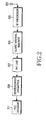
- FIG. 1 is a block diagram schematically illustrating a transmitter of a conventional OFDM communication system. More specifically, the transmitter illustrated in FIG. 1 includes a Forward Error Correction (FEC) encoder 101, an interleaver/mapper 103, an Inverse Fourier Transform (IFFT) unit 105, a guard interval inserter 107, a Radio Frequency (RF) processor 109, and a transmission (Tx) antenna 111.
- FEC Forward Error Correction
- IFFT Inverse Fourier Transform
- RF Radio Frequency
- Tx transmission
- the FEC encoder 101 when data to be transmitted (including user data bits and control data bits) occur in the OFDM transmitter, the data is input to the FEC encoder 101.
- the user data bits and control data bits will be referred to as "information data bits.”
- the FEC encoder 101 encodes the input information data bits according to a predetermined coding scheme and outputs the encoded data to the interleaver/mapper 103.
- the coding scheme may be a convolutional coding scheme or a turbo coding scheme with a predetermined coding rate.
- the interleaver/mapper 103 interleaves and modulates the coded bits output from the FEC encoder 101 according to a predetermined interleaving scheme and a predetermined modulation scheme, thereby generating modulated symbols. Then, the interleaver/mapper 103 outputs the generated modulated symbols to the IFFT unit 105.
- the modulation scheme may be a QPSK (Quadrature Phase Shift Keying) scheme, an 8PSK (Phase Shift Keying) scheme, QAM (Quadrature Amplitude Modulation) or a 16QAM scheme.
- the IFFT unit 105 performs IFFT on the signal from the interleaver/mapper 103 and outputs the IFFT-ed signal to the guard interval inserter 107.
- the guard interval inserter 107 inserts a guard interval into the signal from the IFFT unit 105 and then outputs the signal to the RF processor 109.
- the guard interval is inserted to remove interference between a previous OFDM symbol transmitted at a previous OFDM symbol time and a current OFDM symbol to be transmitted at a current OFDM symbol time in an OFDM communication system.
- a cyclic prefix method or a cyclic postfix method may be used.
- a predetermined number of last samples of an OFDM symbol in a time domain are copied and inserted into a valid OFDM symbol
- a predetermined number of first samples of an OFDM symbol in a time domain are copied and inserted into a valid OFDM symbol.
- the RF processor 109 processes the signal from the IFFT unit 105 so that the signal can be transmitted through an actual channel. Then, the RF processor 109 transmits the processed signal through the Tx antenna 111.
- the RF processor 109 normally includes a filter and a front end unit for performing operation in relation to RF signal conversion in the RF path, including digital filtering.
- FIG. 2 is a block diagram schematically illustrating a receiver of a conventional OFDM communication system. More specifically, the receiver illustrated in FIG. 2 includes a reception (Rx) antenna 201, an RF processor 203, a guard interval remover 205, a Fast Fourier Transform (FFT) unit 207, a deinterleaver/demapper 209, and an FEC decoder 211.
- the received signal contains noise added to the signal when the signal passed through the multi-path channel.
- the signal received through the Rx antenna 201 is input to the RF processor 203, which down-converts the signal into a signal of an Intermediate Frequency (IF) and then outputs the down-converted signal to the guard interval remover 205.
- IF Intermediate Frequency
- the guard interval remover 205 receives the signal from the RF processor 203, eliminates the guard interval from the received signal, and then outputs the signal to the FFT unit 207.
- the FFT unit 207 performs FFT on the signal output from the guard interval remover 205 and then outputs the FFT-ed signal to the deinterleaver/demapper 209.
- the deinterleaver/demapper 209 deinterleaves and demodulates the signal from the FFT unit 207 according to schemes corresponding to the interleaving scheme and the modulation scheme used in the transmitter, and then outputs it to the FEC decoder 211.
- the FEC decoder 211 decodes the signal from the deinterleaver/demapper 209 according to a decoding scheme corresponding to the coding scheme employed in the transmitter, and then outputs the same signal as the information data bits transmitted from the transmitter.
- Equation (1) The IFFT performed in the transmitter can be defined by Equation (1) below.
- Equation (1) X k denotes a complex amplitude of a subcarrier.
- PAPR 10 log ( ⁇ x ⁇ ⁇ 2 ⁇ [ ⁇ x ⁇ 2 2 ] / N )
- Equation (2) x can take different values. Therefore, we say bout of the signal probability, when PAPR magnitudes excess the PAPR 0 specified value, as shown in Equation (3) below. Pr ( PAPR > PAPR 0 )
- U.S. Patent No. 6,424,681 "Peak to Average Power Ratio Reduction" discloses a method of PAPR value reduction by redundancy of subcarriers. That is, one part of subcarriers is used for information signal transmittance, i.e., the subcarriers are modulated by information symbols, and another part of the subcarriers is used for generation of a correction signal that is extracted from the resultant time signal got at the IFFT output and leading to PAPR 0 value reduction at one and the same probability value.
- the PAPR reduction method as described above is usually called the "Tone Reservation (TR)" method.
- TR Tone Reservation
- a part of subcarriers i.e., tones
- the tones that are not used for transmitting an information signal are disregarded, and the information signals are restored from the other tones.
- the structure of the receiver can be simplified.
- the gradient algorithm can be obtained by applying the clipping scheme to the TR method.
- a signal having an impulse characteristic is generated using the tones that are not used for information signal transmission, and the output signal of the IFFT unit is then subjected to the clipping by using the generated signal having the impulse characteristic. Then, if the generated signal having the impulse characteristic is added to the output signal of the IFFT unit, data distortion occurs in only the tones that are not used for information signal transmission and does not occur in the other frequency domain.
- Equation (4) a part of the subcarriers is modulated by the information signal X k , which is defined by Equation (4) below.
- X k ⁇ X k , k ⁇ ⁇ i 1 , i 2 , ... , i L ⁇ 0 , k ⁇ ⁇ i 1 , i 2 , ... , i L ⁇
- Equation (4) zero indicates that subcarriers are not modulated by the information symbols (i.e., are made redundant).
- the redundant subcarriers are modulated by the specially selected bit sequence and can be expressed by Equation (5) below.
- C k ⁇ C k , k ⁇ ⁇ i 1 , i 2 , ... , i L ⁇ 0 , k ⁇ ⁇ i 1 , i 2 , ... , i L ⁇
- the information signals are allocated to the subcarriers other than the redundant subcarriers as noted from Equation (4), and the correction signals are allocated to the other redundant subcarriers than the subcarriers of Equation (4), as noted from Equation (5).
- a signal of (X+C) which is obtained by adding a predetermined input signal X and a correction signal C, is output through the IFFT unit of the transmitter.
- the generated signal can be expressed by Equation (6) below.
- Equation (7) C k symbols of Equation (5) are selected to minimize the PAPR as shown in Equation (7) below.
- PAPR ( c ⁇ ) min c ⁇ x + c ⁇ ⁇ 2 ⁇ [ ⁇ x ⁇ 2 2 ] / N ⁇ ⁇ x ⁇ ⁇ 2 ⁇ [ ⁇ x ⁇ 2 2 ] / N
- a proper signal e.g., the correction signal C
- the found correction signal C is then added to the input signal X, in order to reduce the PAPR of the resultant signal (X+C).
- FIG. 3 is a block diagram for illustrating an operation of a transmitter with a subcarrier redundancy in a conventional OFDM communication system. More specifically, FIG. 3 schematically illustrates a multi-carrier transmitter using the TR method in order to reduce the PAPR.
- a serial-to-parallel (S/P) converter 301 converts input data to parallel data and then outputs the converted parallel data to a plurality of modulators including a first modulator 303 through a sixth modulator 313. That is, the input information signal is distributed to a plurality of subcarriers by the serial-to-parallel converter 301. In distributing the information signal, some of the subcarriers are not used, that is, they are left as redundant subcarriers.
- Each of the first modulator 303 through the sixth modulator 313 receives the signal from the serial-to-parallel converter 301, modulates the signal through a modulation scheme set in advance in the system, and then outputs the modulated signal to the multiplexer 315.
- the multiplexer 315 multiplexes the signals from the first modulator 303 through the sixth modulator 313 and then outputs a multiplexed signal to the kernel engine 317. That is, the modulated subcarriers are multiplexed into one signal by the multiplexer 315.
- the kernel engine 317 reduces the PAPR value by performing signal correction for the signal from the multiplexer 315, and then outputs the corrected signal. That is, the kernel engine 317 performs correction for reducing the PAPR value of the signal output from the multiplexer 315.
- the correction described above is performed by addition to signal X of a correction signal C that provides the output signal with a PAPR value not crossing the predetermined threshold PAPR 0 .
- the present invention proposes a method for minimizing the PAPR while maintaining high transmission capacity through the missed correction procedure. More specifically, according to the proposed by the present invention, in order to reduce a PAPR in an OFDM communication system, symbols are classified into full-symbols and sub-symbols, e.g., half-symbols, and a peak value for each symbol is detected. When a corresponding PAPR value is larger than a predetermined threshold set up in the system, the half-symbol is transmitted to reduce the PAPR.
- the transmitter according to the present invention includes an additional IFFT unit, and the receiver includes a symbol detector for detecting a full-symbol or a half-symbol and an additional buffer for collecting the full-symbol.
- the technical result is achieved by application of a new PAPR reduction method based on the fact that not all multi-carrier symbols have signal sampling with anomalous amplitude deviations. That is, the overwhelming majority of symbols do not exceed the predetermined PAPR 0 threshold, and accordingly, do not require any additional reduction means. A relatively insignificant quantity of symbols include anomalous samples.
- sub-symbols For example, into two, each of which includes the diminished number of subcarriers modulated by the input data.
- the remaining subcarriers are not used, and they have zero amplitude. Accordingly, sub-symbols will not have anomalous amplitude deviations, because the probability of anomalous peak generation is reduced by subcarrier quantity diminishment.
- the receiver according to the present invention also detects the diminished sub-symbols, performs demodulation, and then multiplexes the sub-symbols into one signal.
- a modified deinterleaver is used for the demodulation according to the present invention.
- the multiplexing of the demodulated sub-symbols into one signal is performed in such a way that the outcome is a series of information symbols matching the sequence of the modulated full multi-carrier symbol. Thereafter, further processing (e.g., decoding) is done in a similar way to that in a common receiver.
- FIG. 4 is a block diagram schematically illustrating a transmitter according to an embodiment of the present invention. More specifically, FIG. 4 schematically illustrates the multi-carrier transmitter, using a symbol dividing scheme in order to reduce the PAPR.
- the transmitter includes a symbol divider 401, a plurality of modulators including a first modulator 403 through a sixth modulator 413, a multiplexer 415, and a peak detector 417.
- the information data is input to the symbol divider 401.
- the symbol divider 401 divide the information data into information signals corresponding to subcarriers and then outputs the information signals to the first modulator 403 through the sixth modulator 413.
- the information signals may be distributed to either all accessible subcarriers or some of the accessible subcarriers, e.g., half of all accessible subcarriers.
- the multi-carrier symbol is transmitted at several stages as illustrated in FIG. 5. For example, in case of double dividing, a first symbol part is transmitted at a first stage, and a second symbol part is then transmitted at a second stage. This process will be described later in more detail with reference to FIG. 5.
- Each of the first modulator 403 through the sixth modulator 413 receives the signal, i.e., subcarrier, from the symbol divider 401, modulates the subcarrier according to the modulation scheme set in advance in the system, and then outputs the modulated subcarrier to the multiplexer 415.
- the multiplexer 415 multiplexes the signals from the first modulator 403 through the sixth modulator 413 into one time symbol and then outputs the time symbol to the peak detector 417.
- the peak detector 417 detects a peak value for the symbol from the multiplexer 415, determines if the symbol has been divid and if the symbol has anomalous amplitude deviation, and then outputs data corresponding to the determination.
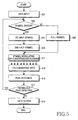
- FIG. 5 is a flowchart for schematically illustrating signal processing by a transmitter according to a preferred embodiment of the present invention. More specifically, FIG. 5 illustrates symbol dividing and peak detection by the transmitter. It is noted, however, that while FIG. 5 illustrates in detail the algorithm of symbol dividing into two sub-symbols, the present invention is not limited to the illustrated example but can be applied whenever the symbol is divided into more than two sub-symbols.
- the input data is passed to the symbol divider 401.
- the divider 401 determines whether to divide the symbol into sub-symbols in step 503.
- the peak detector 417 plays an important role in the determining whether to divide the symbol into sub-symbols. That is, the peak detector 417 compares the synthesized time impulse with the threshold PAPR 0 and then reports the result of the comparison to the symbol divider 401. Thereafter, the symbol divider 401 makes a decision about the dividing in accordance with the reported result.
- step 505 the symbol divider 401 generates and outputs a full-symbol.
- the full-symbol output from the symbol divider 401 is modulated using subcarriers by the first modulator 403 through the sixth modulator 413 in step 511. Then, in step 513, the full-symbols from the modulators are converted into one time symbol through serial conversion and IFFT in the multiplexer 415. Thereafter, the time symbol is input to the peak detector 417, and the peak detector 417 detects a peak of the time symbol in step 515.
- the peak detector 417 compares the peak power of the time symbol with the predetermined threshold PAPR 0 set in advance in the system. When the detected peak power of the time symbol does not exceed the threshold PAPR 0 , the time symbol is transmitted to the output in step 519. However, when the detected peak power of the time symbol exceeds the threshold, that is, when an anomalous peak is detected for the symbol, the full-symbols are not transmitted to the output. That is, when an anomalous peak is detected for the symbol, the peak detector 417 reports the detection to the symbol divider 401. Thereafter, the symbol divider 401 divides the full-symbol based on the report from the peak detector 417.
- FIG. 5 corresponds to the case when each full-symbol is divided into two sub-symbols (half-symbols). That is, if it is determined that symbol dividing is necessary in step 503, the symbol divider 401 divides the full-symbol into two sub-symbols, transmits a first sub-symbol (a half part of the full-symbol) at the first stage in step 507, and then transmits a second sub-symbol (the other half part of the full-symbol) at the second stage in step 509.
- each of the two sub-symbols output from the symbol divider 401 is modulated by using subcarriers by the first modulator 403 through the sixth modulator 413 in step 511.
- the sub-symbols from the modulators are converted into one time symbol through serial conversion and IFFT in the multiplexer 415.
- no threshold crossing is detected in step 517. Therefore, according to the present invention, two half-symbols not exceed are serially transmitted to the output instead of one full multi-carrier symbol with anomalous threshold exceeding.
- the above-described process may lead to information frame relay duration increase.
- the percentage ratio of anomalous symbols to symbols quantity is not too high, the transmittance duration increase is also not significant.
- the first symbol part is extracted from the output in case of anomalous peak fixation in the peak detector 417.
- FIG. 6 is a block diagram schematically illustrating a receiver according to an embodiment of the present invention. More specifically, FIG. 6 illustrates a schematic construction of a multi-carrier receiver using a symbol dividing scheme in order to reduce the PAPR.
- the receiver includes a serial-to-parallel converter (FFT unit) 601, a symbol detector 603, a demodulator 605, and a deinterleaver 607.
- the serial-to-parallel converter (FFT unit) 601 converts input data of a time domain into parallel symbols of a frequency domain and outputs the converted symbols to the symbol detector 603.
- the symbol detector 603 checks if each of the symbols from the serial-to-parallel converter (FFT unit) 601 is a full-symbol.
- the symbol detector 603 analyzes signal amplitude on subcarriers that are not modulated, i.e., having zero amplitude, in the case of symbol dividing into sub-symbols. For example, it is possible to diagnose the arrival of an unfull half-symbol through comparison of signal amplitude sum (e.g., complex envelope module) on these subcarriers or amplitude square sum with the threshold R 0 .
- signal amplitude sum e.g., complex envelope module
- the demodulator 605 demodulates only the subcarriers on which information symbols are transmitted. Accordingly, the deinterleaver 607 converts symbols transmitted on the selected subcarriers to time symbol sequence. Therefore, conversion is done in such a way that the time sequence remains the same, as during full symbol transmission.
- the receiver processes the second half-symbol. Accordingly, there is no need to detect the unfull signal arrival, because it is clear that the second half-symbol has to follow the first one.
- FIG. 7 is a flowchart of signal processing in the receiver according to an embodiment of the present invention. More specifically, FIG. 7 illustrates a processing algorithm of a multi-carrier signal with sub-symbol dividing. It is noted, however, that while the algorithm illustrated in FIG. 7 is for symbol dividing into two sub-symbols, the present invention is not limited to the illustrated example, but can be applied when the symbol is divide into more than two sub-symbols.
- step 701 data is input in step 701. Whether an input signal for the input data is a full-symbol or a half-symbol is determined in steps 703 and 705. When the input signal is a half-symbol, the process returns to step 701 in which another half-symbol is received. However, when the input signal is a full-symbol, the process proceeds to step 707, wherein the data is output.
- FIG. 8 is a block diagram schematically illustrating a receiver of an OFDM communication system according to a preferred embodiment of the present invention. More specifically, the receiver of the OFDM communication system illustrated in FIG. 8 includes a reception (Rx) antenna 801, an RF processor 803, a guard interval remover 805, an FFT unit 807, a symbol detector 809, a deinterleaver/demapper 811, and an FEC decoder 813.
- Rx reception
- the received signal contains noise added to the signal while the signal passes through the multi-path channel.
- the signal received through the Rx antenna 801 is input to the RF processor 803, and the RF processor 803 down-converts the signal received through the Rx antenna into a signal of an Intermediate Frequency (IF) and then outputs the down-converted signal to the guard interval remover 805.
- IF Intermediate Frequency
- the guard interval remover 805 receives the signal from the RF processor 803, removes the guard interval from the received signal, and then outputs the signal to the FFT unit 807.
- the FFT unit 807 performs FFT on the signal output from the guard interval remover 805 and then outputs the FFT-ed signal to the symbol detector 809.
- the symbol detector 809 detects presence of an unfull symbol, for example, it detects the presence of a symbol in which only half of the subcarriers are modulated by the information signal, and the remaining part has zero amplitude, i.e., is absent. Then, the symbol detector 809 outputs the detected symbol to the deinterleaver/demapper 811.
- the deinterleaver/demapper 811 After an unfull symbol detection, the deinterleaver/demapper 811 performs such unfull symbol demodulation as described above, which takes into account that not all the subcarriers were used for the information transmittance.
- the sub-symbols After demodulation of all sub-symbols, which form the initial full symbol, the sub-symbols are multiplexed in an output information flow in such a way that the demodulated symbol order matches the symbol order of the initial information flow that is further forwarded to the FEC decoder 813.
- FIG. 9 is a block diagram schematically illustrating a transmitter of an OFDM communication system according to a preferred embodiment of the present invention.
- the transmitter includes an FEC encoder 901, an interleaver/mapper 903, a symbol divider 905, a plurality of IFFT units 907 through 909, a peak detector 911, a guard interval inserter 913, an RF processor 915, and a Tx antenna 917.
- data to be transmitted (including user data bits and control data bits) occurs in the OFDM transmitter, the data is input to the FEC encoder 901. As indicated above, the user data bits and control data bits are referred to herein as "information data bits.”
- the FEC encoder 901 encodes the input information data bits according to a predetermined coding scheme and outputs the encoded data to the interleaver/mapper 903.
- the coding scheme may be a convolutional coding scheme or a turbo coding scheme having a predetermined coding rate.
- the interleaver/mapper 903 interleaves and modulates the coded bits output from the FEC encoder 901 according to a predetermined interleaving scheme and a predetermined modulation scheme, thereby generating modulated symbols.
- the interleaver/mapper 903 outputs the generated modulated symbols to the symbol divider 905.
- the modulation scheme may be a QPSK (Quadrature Phase Shift Keying) scheme, an 8PSK (Phase Shift Keying) scheme, a QAM (Quadrature Amplitude Modulation) or a 16QAM (Quadrature Amplitude Modulation) scheme.
- the symbol divider 905 generates a full-symbol sequence or at least two sub-symbol sequences using the signal output from the interleaver/mapper 903 and then outputs the generated full-symbol sequence or sub-symbol sequences to the corresponding IFFT unit, for example, the IFFT unit 907 and/or the IFFT unit 909.
- Each of the IFFT units 907 through 909 performs IFFT on the signal from the interleaver/mapper 903 or the symbol divider 905 and outputs the IFFT-ed signal to the peak detector 911.
- the IFFT units 907 through 909 receive one full-symbol sequence or at least two sub-symbol sequences from the symbol divider 905, simultaneously converts the input sequence or sequences into a time domain symbol sequence, and then outputs the converted sequence or sequences to the peak detector 911.
- the transmitter illustrated in FIG. 9 includes a plurality of IFFT units, the present invention is not limited to the example shown in FIG. 9. Instead, the transmitter according to the present invention may include a single IFFT unit that can perform an operation proper for the symbol dividing. Further, the single IFFT unit may be adaptively implemented properly for the symbol dividing in accordance with system setup. For example, when the symbol is divide into half-symbols, the transmitter may include one or two IFFT units.
- the peak detector 911 receives the full-symbol sequence or at least two sub-symbol sequences from the IFFT units 907 through 909, and detects presence of a peak value of the symbols. When the peak detector 911 detects an anomalous peak, the peak detector 911 reports the detection to the symbol divider 905, such that the symbol divider 905 performs symbol dividing. When the peak detector 911 detects no anomalous peak, the peak detector 911 outputs the corresponding symbol sequence to the guard interval inserter 913.
- the guard interval inserter 913 inserts a guard interval into the signal from the peak detector 911 and then outputs the signal to the RF processor 915.
- the guard interval removes interference between a previous OFDM symbol transmitted at a previous OFDM symbol time and a current OFDM symbol to be transmitted at a current OFDM symbol time in an OFDM communication system.
- a cyclic prefix method or a cyclic postfix method may be used.
- the cyclic prefix method a predetermined number of last samples of an OFDM symbol in a time domain are copied and inserted into a valid OFDM symbol
- a predetermined number of first samples of an OFDM symbol in a time domain are copied and inserted into a valid OFDM symbol.
- the RF processor 915 processes the signal from the guard interval inserter 913 so that the signal can be transmitted through an actual channel. Then, the RF processor 915 transmits the processed signal through the Tx antenna 917.
- the RF processor 915 includes a predetermined filter and a front end unit for performing operation in relation to RF signal conversion in the RF path, including digital filtering.
- the present invention proposes an apparatus and a method for minimizing the PAPR in an OFDM communication system.
- the PAPR minimization method of the invention when the peak value of an OFDM symbol exceeds a maximum allowable level, the OFDM symbol is divided into more than one sub-symbol, in order to reduce the PAPR.
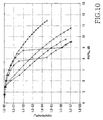
- FIG. 10 is a graph illustrating the performance of the present invention.
- FIG. 10 illustrates results of a modulation that was performed to estimate effectiveness of the method of the present invention, i.e., the symbol dividing method. The results are presented in comparison with the iteration method based on subcarrier redundancy.
- the present invention provides an apparatus and a method that reduces a PAPR in a broadband wireless communication system. Further, the present invention can achieve PAPR reduction with a high transmission capacity without a signal correction process.
- symbols are classified into full-symbols and sub-symbols.
- a PAPR value of each symbol is larger than a predetermined threshold set up in the system, the sub-symbols are transmitted in such a way that effectively reduces the PAPR.
Landscapes
- Engineering & Computer Science (AREA)
- Computer Networks & Wireless Communication (AREA)
- Signal Processing (AREA)
- Transmitters (AREA)
- Digital Transmission Methods That Use Modulated Carrier Waves (AREA)
- Cable Transmission Systems, Equalization Of Radio And Reduction Of Echo (AREA)
- Radio Relay Systems (AREA)
Applications Claiming Priority (1)
| Application Number | Priority Date | Filing Date | Title |
|---|---|---|---|
| RU2004134537 | 2004-11-26 |
Publications (3)
| Publication Number | Publication Date |
|---|---|
| EP1662737A2 true EP1662737A2 (de) | 2006-05-31 |
| EP1662737A3 EP1662737A3 (de) | 2006-11-22 |
| EP1662737B1 EP1662737B1 (de) | 2008-04-23 |
Family
ID=36050506
Family Applications (1)
| Application Number | Title | Priority Date | Filing Date |
|---|---|---|---|
| EP05025909A Expired - Lifetime EP1662737B1 (de) | 2004-11-26 | 2005-11-28 | Vorrichtung und Verfahren zur Verringerung des Verhältnisses von Spitzen zur Durchschnittsleistung in Mehrträgerkommunikationssystemen |
Country Status (6)
| Country | Link |
|---|---|
| US (1) | US20060115010A1 (de) |
| EP (1) | EP1662737B1 (de) |
| KR (1) | KR20060059221A (de) |
| AT (1) | ATE393527T1 (de) |
| DE (1) | DE602005006218T2 (de) |
| ES (1) | ES2304656T3 (de) |
Cited By (4)
| Publication number | Priority date | Publication date | Assignee | Title |
|---|---|---|---|---|
| WO2008060202A1 (en) * | 2006-11-13 | 2008-05-22 | Telefonaktiebolaget Lm Ericsson (Publ) | A method for limiting local bandwidth impairment using tone reservation |
| WO2013113282A1 (en) * | 2012-01-31 | 2013-08-08 | Huawei Technologies Co., Ltd. | Methods and systems for peak-to-average power reduction without reducing data rate |
| US9077597B2 (en) | 2009-07-15 | 2015-07-07 | Kabushiki Kaisha Toshiba | Data communication method and apparatus |
| CN105634651A (zh) * | 2014-10-27 | 2016-06-01 | 中南大学 | 一种预编码结合指数压扩技术降低ofdm系统papr的方法 |
Families Citing this family (21)
| Publication number | Priority date | Publication date | Assignee | Title |
|---|---|---|---|---|
| KR100575980B1 (ko) * | 2002-12-24 | 2006-05-02 | 삼성전자주식회사 | 직교 주파수 분할 다중 방식을 사용하는 통신 시스템에서피크대 평균 전력비를 최소화시키는 장치 및 방법 |
| US7551679B2 (en) * | 2006-02-03 | 2009-06-23 | Ati Technologies, Inc. | Symmetrical data signal processing |
| US8509322B2 (en) * | 2006-03-30 | 2013-08-13 | Intel Corporation | System, method and device of adjusting a wireless communication signal |
| JP4847392B2 (ja) * | 2006-05-29 | 2011-12-28 | 富士通株式会社 | 通信システム、その送信機、受信機、通信方法 |
| CN101647217B (zh) * | 2007-04-13 | 2013-02-27 | 富士通株式会社 | 峰值抑制电路、发送装置以及峰值抑制方法 |
| US8571126B2 (en) * | 2007-05-15 | 2013-10-29 | Rambus Inc. | Multi-antenna transmitter for multi-tone signaling |
| KR20090024623A (ko) * | 2007-09-04 | 2009-03-09 | 한국전자통신연구원 | 고속 무선 통신을 위한 프레임 구성 방법 및 이를 이용한 고속 무선 통신 장치 |
| US20090080556A1 (en) * | 2007-09-25 | 2009-03-26 | Chunjie Duan | Reducing Peak-to-Average-Power-Ratio in OFDM/OFDMA Signals by Deliberate Error Injection |
| WO2012030319A2 (en) | 2009-06-26 | 2012-03-08 | Hypres, Inc. | System and method for controlling combined radio signals |
| US9369885B2 (en) | 2011-04-12 | 2016-06-14 | Qualcomm Incorporated | Method and apparatus for selecting reference signal tones for decoding a channel |
| US8787873B1 (en) | 2011-11-04 | 2014-07-22 | Plusn Llc | System and method for communicating using bandwidth on demand |
| US20140334421A1 (en) * | 2011-12-07 | 2014-11-13 | Drexel University | Joint bit loading and symbol rotation scheme for multi-carrier systems in siso and mimo links |
| US8982724B2 (en) * | 2012-12-17 | 2015-03-17 | Intel Corporation | Systems and methods for implementing peak-to-average power ratio reduction for OFDMA modulation |
| US9148182B2 (en) * | 2013-10-09 | 2015-09-29 | Maxlinear, Inc. | Power combining power amplifier architectures and methods |
| CN105814856B (zh) | 2013-11-26 | 2019-02-12 | 普鲁斯恩公司 | 控制组合波形的方法、设备和系统、组合多个信号的设备 |
| US20150223176A1 (en) * | 2014-02-02 | 2015-08-06 | Redline Innovations Group Inc. | Systems and methods for reducing peak to average power ratio |
| US10848359B2 (en) | 2016-09-30 | 2020-11-24 | Qualcomm Incorporated | Virtual symbol splitting techniques in wireless communications |
| CN111818645B (zh) * | 2019-07-24 | 2023-09-22 | 维沃移动通信有限公司 | 一种信息传输方法、网络设备及终端 |
| CN111654462B (zh) * | 2020-06-03 | 2022-11-11 | 珠海中慧微电子有限公司 | 一种基于符号分拆的降低ofdm信号峰均比值的方法 |
| WO2025239734A1 (ko) * | 2024-05-17 | 2025-11-20 | 엘지전자 주식회사 | 기기에 의해 수행되는 방법, 기기 및 저장 매체 |
| CN121239541A (zh) * | 2024-06-21 | 2025-12-30 | 中兴通讯股份有限公司 | 调制方法、调制装置、电子设备、存储介质及产品 |
Citations (1)
| Publication number | Priority date | Publication date | Assignee | Title |
|---|---|---|---|---|
| US6424681B1 (en) | 1998-04-20 | 2002-07-23 | The Board Of Trustees Of The Leland Stanford Junior University | Peak to average power ratio reduction |
Family Cites Families (5)
| Publication number | Priority date | Publication date | Assignee | Title |
|---|---|---|---|---|
| KR100480765B1 (ko) * | 1999-03-26 | 2005-04-06 | 삼성전자주식회사 | 직교 주파수 분할 다중화 전송/수신 시스템 및 이를 이루기위한블록 엔코딩 방법 |
| US6952394B1 (en) * | 1999-05-25 | 2005-10-04 | Samsung Electronics Co., Ltd. | Method for transmitting and receiving orthogonal frequency division multiplexing signal and apparatus therefor |
| JP2003283460A (ja) * | 2002-03-26 | 2003-10-03 | Matsushita Electric Ind Co Ltd | マルチキャリア送信装置およびマルチキャリア送信方法 |
| KR100575980B1 (ko) * | 2002-12-24 | 2006-05-02 | 삼성전자주식회사 | 직교 주파수 분할 다중 방식을 사용하는 통신 시스템에서피크대 평균 전력비를 최소화시키는 장치 및 방법 |
| US7227903B2 (en) * | 2003-07-22 | 2007-06-05 | Mitsubishi Electric Research Laboratories, Inc. | OFDM transmitter for generating FSK modulated signals |
-
2005
- 2005-11-26 KR KR1020050113895A patent/KR20060059221A/ko not_active Ceased
- 2005-11-28 EP EP05025909A patent/EP1662737B1/de not_active Expired - Lifetime
- 2005-11-28 DE DE602005006218T patent/DE602005006218T2/de not_active Expired - Fee Related
- 2005-11-28 ES ES05025909T patent/ES2304656T3/es not_active Expired - Lifetime
- 2005-11-28 US US11/287,758 patent/US20060115010A1/en not_active Abandoned
- 2005-11-28 AT AT05025909T patent/ATE393527T1/de not_active IP Right Cessation
Patent Citations (1)
| Publication number | Priority date | Publication date | Assignee | Title |
|---|---|---|---|---|
| US6424681B1 (en) | 1998-04-20 | 2002-07-23 | The Board Of Trustees Of The Leland Stanford Junior University | Peak to average power ratio reduction |
Cited By (6)
| Publication number | Priority date | Publication date | Assignee | Title |
|---|---|---|---|---|
| WO2008060202A1 (en) * | 2006-11-13 | 2008-05-22 | Telefonaktiebolaget Lm Ericsson (Publ) | A method for limiting local bandwidth impairment using tone reservation |
| US8254478B2 (en) | 2006-11-13 | 2012-08-28 | Telefonaktiebolaget L M Ericsson (Publ) | Method for limiting local bandwidth impairment using tone reservation |
| US9077597B2 (en) | 2009-07-15 | 2015-07-07 | Kabushiki Kaisha Toshiba | Data communication method and apparatus |
| WO2013113282A1 (en) * | 2012-01-31 | 2013-08-08 | Huawei Technologies Co., Ltd. | Methods and systems for peak-to-average power reduction without reducing data rate |
| US8654887B2 (en) | 2012-01-31 | 2014-02-18 | Futurewei Technologies, Inc. | Methods and systems for peak-to-average power reduction without reducing data rate |
| CN105634651A (zh) * | 2014-10-27 | 2016-06-01 | 中南大学 | 一种预编码结合指数压扩技术降低ofdm系统papr的方法 |
Also Published As
| Publication number | Publication date |
|---|---|
| DE602005006218T2 (de) | 2009-06-18 |
| DE602005006218D1 (de) | 2008-06-05 |
| EP1662737A3 (de) | 2006-11-22 |
| ES2304656T3 (es) | 2008-10-16 |
| KR20060059221A (ko) | 2006-06-01 |
| US20060115010A1 (en) | 2006-06-01 |
| ATE393527T1 (de) | 2008-05-15 |
| EP1662737B1 (de) | 2008-04-23 |
Similar Documents
| Publication | Publication Date | Title |
|---|---|---|
| EP1662737B1 (de) | Vorrichtung und Verfahren zur Verringerung des Verhältnisses von Spitzen zur Durchschnittsleistung in Mehrträgerkommunikationssystemen | |
| US7496028B2 (en) | Apparatus and method for minimizing PAPR in an OFDM communication system | |
| US7376074B2 (en) | Apparatus and method for transmitting and receiving side information of a partial transmit sequence in an OFDM communication system | |
| CN1849761B (zh) | 降低正交频分复用通信系统中峰均功率比的装置和方法 | |
| KR100434473B1 (ko) | 직교주파수 분할 다중 시스템에서 채널 복호 장치 및 방법 | |
| US9197374B2 (en) | Repetition coding for a wireless system | |
| KR100724949B1 (ko) | 주파수 분할 다중접속 기반 무선통신 시스템에서 데이터와제어 정보의 다중화 방법 및 장치 | |
| KR100688118B1 (ko) | 직교 주파수 분할 다중 통신 시스템에서 피크 전력 대평균 전력비를 감소시키기 위한 장치 및 방법 | |
| RU2433555C2 (ru) | Переменное кодирование и модулирование подканала мультиплексирования с ортогональным частотным разделением | |
| US20040008616A1 (en) | Apparatus and method for transmitting and receiving side information about selective mapping in an orthogonal frequency division multiplexing communication system | |
| US20040257979A1 (en) | Apparatus and method for tranmitting and receiving a pilot pattern for identification of a base station in an OFDM communication system | |
| CN1961513B (zh) | 多载波通信环境中语音业务的自适应调度 | |
| CN101599946B (zh) | 用于多载波系统的新的帧与信令模式结构 | |
| US20050089109A1 (en) | Apparatus and method for PAPR reduction in an OFDM communication system | |
| EP1780966A1 (de) | Blind Selective Mapping (SLM) unter Verwendung von Pilotsignale | |
| EP1530312B1 (de) | Vorrichtung und Verfahren zur Unterdrückung von Interferenzsignalen in einem System mit mehreren Antennen | |
| US20070121738A1 (en) | Transmission apparatus and peak suppression method | |
| US20040257981A1 (en) | Apparatus and method for transmitting and receiving pilot patterns for identifying base stations in an OFDM communication system | |
| Xu et al. | Bandwidth compressed carrier aggregation | |
| EP2214366B1 (de) | Kabelsystem für digitale Videoübertragung und Verfahren zur Verarbeitung von reserviertem Ton | |
| EP3007437A1 (de) | Vorrichtung zum senden von rundfunksignalen, vorrichtung zum empfangen von rundfunksignalen, verfahren zum senden von rundfunksignalen und verfahren zum empfangen von rundfunksignalen | |
| EP2190159B1 (de) | Reduktion des Crest-Faktors in Mehrträgerübertragungssystemen | |
| CN1984110B (zh) | 降低峰均比的方法和具有低峰均比的正交频分复用系统 | |
| KR100789135B1 (ko) | 순환 지연 오프셋을 적용한 다이버시티 구현 장치 및 방법 | |
| US20070121737A1 (en) | Transmission apparatus and peak suppression method |
Legal Events
| Date | Code | Title | Description |
|---|---|---|---|
| PUAI | Public reference made under article 153(3) epc to a published international application that has entered the european phase |
Free format text: ORIGINAL CODE: 0009012 |
|
| 17P | Request for examination filed |
Effective date: 20051128 |
|
| AK | Designated contracting states |
Kind code of ref document: A2 Designated state(s): AT BE BG CH CY CZ DE DK EE ES FI FR GB GR HU IE IS IT LI LT LU LV MC NL PL PT RO SE SI SK TR |
|
| AX | Request for extension of the european patent |
Extension state: AL BA HR MK YU |
|
| PUAL | Search report despatched |
Free format text: ORIGINAL CODE: 0009013 |
|
| AK | Designated contracting states |
Kind code of ref document: A3 Designated state(s): AT BE BG CH CY CZ DE DK EE ES FI FR GB GR HU IE IS IT LI LT LU LV MC NL PL PT RO SE SI SK TR |
|
| AX | Request for extension of the european patent |
Extension state: AL BA HR MK YU |
|
| 17Q | First examination report despatched |
Effective date: 20070104 |
|
| AKX | Designation fees paid |
Designated state(s): AT BE BG CH CY CZ DE DK EE ES FI FR GB GR HU IE IS IT LI LT LU LV MC NL PL PT RO SE SI SK TR |
|
| GRAP | Despatch of communication of intention to grant a patent |
Free format text: ORIGINAL CODE: EPIDOSNIGR1 |
|
| GRAS | Grant fee paid |
Free format text: ORIGINAL CODE: EPIDOSNIGR3 |
|
| GRAA | (expected) grant |
Free format text: ORIGINAL CODE: 0009210 |
|
| AK | Designated contracting states |
Kind code of ref document: B1 Designated state(s): AT BE BG CH CY CZ DE DK EE ES FI FR GB GR HU IE IS IT LI LT LU LV MC NL PL PT RO SE SI SK TR |
|
| REG | Reference to a national code |
Ref country code: GB Ref legal event code: FG4D |
|
| REG | Reference to a national code |
Ref country code: CH Ref legal event code: EP |
|
| REF | Corresponds to: |
Ref document number: 602005006218 Country of ref document: DE Date of ref document: 20080605 Kind code of ref document: P |
|
| REG | Reference to a national code |
Ref country code: IE Ref legal event code: FG4D Free format text: LANGUAGE OF EP DOCUMENT: FRENCH |
|
| PG25 | Lapsed in a contracting state [announced via postgrant information from national office to epo] |
Ref country code: SI Free format text: LAPSE BECAUSE OF FAILURE TO SUBMIT A TRANSLATION OF THE DESCRIPTION OR TO PAY THE FEE WITHIN THE PRESCRIBED TIME-LIMIT Effective date: 20080423 |
|
| REG | Reference to a national code |
Ref country code: ES Ref legal event code: FG2A Ref document number: 2304656 Country of ref document: ES Kind code of ref document: T3 |
|
| PG25 | Lapsed in a contracting state [announced via postgrant information from national office to epo] |
Ref country code: PT Free format text: LAPSE BECAUSE OF FAILURE TO SUBMIT A TRANSLATION OF THE DESCRIPTION OR TO PAY THE FEE WITHIN THE PRESCRIBED TIME-LIMIT Effective date: 20080923 Ref country code: FI Free format text: LAPSE BECAUSE OF FAILURE TO SUBMIT A TRANSLATION OF THE DESCRIPTION OR TO PAY THE FEE WITHIN THE PRESCRIBED TIME-LIMIT Effective date: 20080423 Ref country code: BG Free format text: LAPSE BECAUSE OF FAILURE TO SUBMIT A TRANSLATION OF THE DESCRIPTION OR TO PAY THE FEE WITHIN THE PRESCRIBED TIME-LIMIT Effective date: 20080723 |
|
| PG25 | Lapsed in a contracting state [announced via postgrant information from national office to epo] |
Ref country code: AT Free format text: LAPSE BECAUSE OF FAILURE TO SUBMIT A TRANSLATION OF THE DESCRIPTION OR TO PAY THE FEE WITHIN THE PRESCRIBED TIME-LIMIT Effective date: 20080423 Ref country code: PL Free format text: LAPSE BECAUSE OF FAILURE TO SUBMIT A TRANSLATION OF THE DESCRIPTION OR TO PAY THE FEE WITHIN THE PRESCRIBED TIME-LIMIT Effective date: 20080423 Ref country code: LV Free format text: LAPSE BECAUSE OF FAILURE TO SUBMIT A TRANSLATION OF THE DESCRIPTION OR TO PAY THE FEE WITHIN THE PRESCRIBED TIME-LIMIT Effective date: 20080423 |
|
| PG25 | Lapsed in a contracting state [announced via postgrant information from national office to epo] |
Ref country code: IS Free format text: LAPSE BECAUSE OF FAILURE TO SUBMIT A TRANSLATION OF THE DESCRIPTION OR TO PAY THE FEE WITHIN THE PRESCRIBED TIME-LIMIT Effective date: 20080823 |
|
| PG25 | Lapsed in a contracting state [announced via postgrant information from national office to epo] |
Ref country code: CZ Free format text: LAPSE BECAUSE OF FAILURE TO SUBMIT A TRANSLATION OF THE DESCRIPTION OR TO PAY THE FEE WITHIN THE PRESCRIBED TIME-LIMIT Effective date: 20080423 Ref country code: DK Free format text: LAPSE BECAUSE OF FAILURE TO SUBMIT A TRANSLATION OF THE DESCRIPTION OR TO PAY THE FEE WITHIN THE PRESCRIBED TIME-LIMIT Effective date: 20080423 Ref country code: SE Free format text: LAPSE BECAUSE OF FAILURE TO SUBMIT A TRANSLATION OF THE DESCRIPTION OR TO PAY THE FEE WITHIN THE PRESCRIBED TIME-LIMIT Effective date: 20080723 Ref country code: LT Free format text: LAPSE BECAUSE OF FAILURE TO SUBMIT A TRANSLATION OF THE DESCRIPTION OR TO PAY THE FEE WITHIN THE PRESCRIBED TIME-LIMIT Effective date: 20080423 |
|
| PGFP | Annual fee paid to national office [announced via postgrant information from national office to epo] |
Ref country code: NL Payment date: 20081125 Year of fee payment: 4 |
|
| ET | Fr: translation filed | ||
| PG25 | Lapsed in a contracting state [announced via postgrant information from national office to epo] |
Ref country code: SK Free format text: LAPSE BECAUSE OF FAILURE TO SUBMIT A TRANSLATION OF THE DESCRIPTION OR TO PAY THE FEE WITHIN THE PRESCRIBED TIME-LIMIT Effective date: 20080423 Ref country code: BE Free format text: LAPSE BECAUSE OF FAILURE TO SUBMIT A TRANSLATION OF THE DESCRIPTION OR TO PAY THE FEE WITHIN THE PRESCRIBED TIME-LIMIT Effective date: 20080423 Ref country code: RO Free format text: LAPSE BECAUSE OF FAILURE TO SUBMIT A TRANSLATION OF THE DESCRIPTION OR TO PAY THE FEE WITHIN THE PRESCRIBED TIME-LIMIT Effective date: 20080423 |
|
| PGFP | Annual fee paid to national office [announced via postgrant information from national office to epo] |
Ref country code: ES Payment date: 20081119 Year of fee payment: 4 |
|
| PLBE | No opposition filed within time limit |
Free format text: ORIGINAL CODE: 0009261 |
|
| STAA | Information on the status of an ep patent application or granted ep patent |
Free format text: STATUS: NO OPPOSITION FILED WITHIN TIME LIMIT |
|
| 26N | No opposition filed |
Effective date: 20090126 |
|
| PG25 | Lapsed in a contracting state [announced via postgrant information from national office to epo] |
Ref country code: EE Free format text: LAPSE BECAUSE OF FAILURE TO SUBMIT A TRANSLATION OF THE DESCRIPTION OR TO PAY THE FEE WITHIN THE PRESCRIBED TIME-LIMIT Effective date: 20080423 |
|
| PGFP | Annual fee paid to national office [announced via postgrant information from national office to epo] |
Ref country code: FR Payment date: 20081117 Year of fee payment: 4 |
|
| PGFP | Annual fee paid to national office [announced via postgrant information from national office to epo] |
Ref country code: DE Payment date: 20081223 Year of fee payment: 4 |
|
| PG25 | Lapsed in a contracting state [announced via postgrant information from national office to epo] |
Ref country code: MC Free format text: LAPSE BECAUSE OF NON-PAYMENT OF DUE FEES Effective date: 20081130 |
|
| PG25 | Lapsed in a contracting state [announced via postgrant information from national office to epo] |
Ref country code: IE Free format text: LAPSE BECAUSE OF NON-PAYMENT OF DUE FEES Effective date: 20081128 |
|
| PGFP | Annual fee paid to national office [announced via postgrant information from national office to epo] |
Ref country code: IT Payment date: 20081130 Year of fee payment: 4 |
|
| REG | Reference to a national code |
Ref country code: NL Ref legal event code: V1 Effective date: 20100601 |
|
| REG | Reference to a national code |
Ref country code: CH Ref legal event code: PL |
|
| GBPC | Gb: european patent ceased through non-payment of renewal fee |
Effective date: 20091128 |
|
| PG25 | Lapsed in a contracting state [announced via postgrant information from national office to epo] |
Ref country code: LU Free format text: LAPSE BECAUSE OF NON-PAYMENT OF DUE FEES Effective date: 20081128 Ref country code: HU Free format text: LAPSE BECAUSE OF FAILURE TO SUBMIT A TRANSLATION OF THE DESCRIPTION OR TO PAY THE FEE WITHIN THE PRESCRIBED TIME-LIMIT Effective date: 20081024 Ref country code: CY Free format text: LAPSE BECAUSE OF FAILURE TO SUBMIT A TRANSLATION OF THE DESCRIPTION OR TO PAY THE FEE WITHIN THE PRESCRIBED TIME-LIMIT Effective date: 20080423 |
|
| REG | Reference to a national code |
Ref country code: FR Ref legal event code: ST Effective date: 20100730 |
|
| PG25 | Lapsed in a contracting state [announced via postgrant information from national office to epo] |
Ref country code: TR Free format text: LAPSE BECAUSE OF FAILURE TO SUBMIT A TRANSLATION OF THE DESCRIPTION OR TO PAY THE FEE WITHIN THE PRESCRIBED TIME-LIMIT Effective date: 20080423 |
|
| PG25 | Lapsed in a contracting state [announced via postgrant information from national office to epo] |
Ref country code: LI Free format text: LAPSE BECAUSE OF NON-PAYMENT OF DUE FEES Effective date: 20091130 Ref country code: NL Free format text: LAPSE BECAUSE OF NON-PAYMENT OF DUE FEES Effective date: 20100601 Ref country code: GR Free format text: LAPSE BECAUSE OF FAILURE TO SUBMIT A TRANSLATION OF THE DESCRIPTION OR TO PAY THE FEE WITHIN THE PRESCRIBED TIME-LIMIT Effective date: 20080724 Ref country code: FR Free format text: LAPSE BECAUSE OF NON-PAYMENT OF DUE FEES Effective date: 20091130 Ref country code: CH Free format text: LAPSE BECAUSE OF NON-PAYMENT OF DUE FEES Effective date: 20091130 |
|
| PG25 | Lapsed in a contracting state [announced via postgrant information from national office to epo] |
Ref country code: DE Free format text: LAPSE BECAUSE OF NON-PAYMENT OF DUE FEES Effective date: 20100601 |
|
| PG25 | Lapsed in a contracting state [announced via postgrant information from national office to epo] |
Ref country code: GB Free format text: LAPSE BECAUSE OF NON-PAYMENT OF DUE FEES Effective date: 20091128 |
|
| REG | Reference to a national code |
Ref country code: ES Ref legal event code: FD2A Effective date: 20110309 |
|
| PG25 | Lapsed in a contracting state [announced via postgrant information from national office to epo] |
Ref country code: IT Free format text: LAPSE BECAUSE OF NON-PAYMENT OF DUE FEES Effective date: 20091128 |
|
| PG25 | Lapsed in a contracting state [announced via postgrant information from national office to epo] |
Ref country code: ES Free format text: LAPSE BECAUSE OF NON-PAYMENT OF DUE FEES Effective date: 20110308 |
|
| PG25 | Lapsed in a contracting state [announced via postgrant information from national office to epo] |
Ref country code: ES Free format text: LAPSE BECAUSE OF NON-PAYMENT OF DUE FEES Effective date: 20091129 |