EP1662825B1 - Verfahren zur Zuweisung von Betriebsmitteln in einem Mehrträgersystem und dieses benutzendes Übertragungsvorrichtung - Google Patents
Verfahren zur Zuweisung von Betriebsmitteln in einem Mehrträgersystem und dieses benutzendes Übertragungsvorrichtung Download PDFInfo
- Publication number
- EP1662825B1 EP1662825B1 EP05025686A EP05025686A EP1662825B1 EP 1662825 B1 EP1662825 B1 EP 1662825B1 EP 05025686 A EP05025686 A EP 05025686A EP 05025686 A EP05025686 A EP 05025686A EP 1662825 B1 EP1662825 B1 EP 1662825B1
- Authority
- EP
- European Patent Office
- Prior art keywords
- subcarrier
- sectors
- resources
- service zone
- allocated
- Prior art date
- Legal status (The legal status is an assumption and is not a legal conclusion. Google has not performed a legal analysis and makes no representation as to the accuracy of the status listed.)
- Expired - Lifetime
Links
Images




Classifications
-
- H—ELECTRICITY
- H04—ELECTRIC COMMUNICATION TECHNIQUE
- H04L—TRANSMISSION OF DIGITAL INFORMATION, e.g. TELEGRAPHIC COMMUNICATION
- H04L27/00—Modulated-carrier systems
- H04L27/26—Systems using multi-frequency codes
-
- H—ELECTRICITY
- H04—ELECTRIC COMMUNICATION TECHNIQUE
- H04W—WIRELESS COMMUNICATION NETWORKS
- H04W16/00—Network planning, e.g. coverage or traffic planning tools; Network deployment, e.g. resource partitioning or cells structures
- H04W16/02—Resource partitioning among network components, e.g. reuse partitioning
- H04W16/12—Fixed resource partitioning
-
- H—ELECTRICITY
- H04—ELECTRIC COMMUNICATION TECHNIQUE
- H04W—WIRELESS COMMUNICATION NETWORKS
- H04W16/00—Network planning, e.g. coverage or traffic planning tools; Network deployment, e.g. resource partitioning or cells structures
- H04W16/02—Resource partitioning among network components, e.g. reuse partitioning
-
- H—ELECTRICITY
- H04—ELECTRIC COMMUNICATION TECHNIQUE
- H04W—WIRELESS COMMUNICATION NETWORKS
- H04W16/00—Network planning, e.g. coverage or traffic planning tools; Network deployment, e.g. resource partitioning or cells structures
- H04W16/24—Cell structures
-
- H—ELECTRICITY
- H04—ELECTRIC COMMUNICATION TECHNIQUE
- H04W—WIRELESS COMMUNICATION NETWORKS
- H04W16/00—Network planning, e.g. coverage or traffic planning tools; Network deployment, e.g. resource partitioning or cells structures
- H04W16/24—Cell structures
- H04W16/28—Cell structures using beam steering
-
- H—ELECTRICITY
- H04—ELECTRIC COMMUNICATION TECHNIQUE
- H04W—WIRELESS COMMUNICATION NETWORKS
- H04W28/00—Network traffic management; Network resource management
- H04W28/16—Central resource management; Negotiation of resources or communication parameters, e.g. negotiating bandwidth or QoS [Quality of Service]
Definitions
- the present invention relates generally to a communication system using an Orthogonal Frequency Division Multiple Access (OFDMA) scheme (hereafter referred to as an "OFDMA communication system"), and in particular, to a method for allocating resources for data transmission and an apparatus for transmitting and receiving data using the allocated resources.
- OFDMA Orthogonal Frequency Division Multiple Access
- An Orthogonal Frequency Division Multiplexing (OFDM) scheme can be defined as a two-dimensional access scheme obtained by combining time division access technology and frequency division access technology.
- An OFDM symbol generated by the OFDM scheme is carried by a plurality of subcarriers after being divided, and the subcarriers are grouped into a subchannel before being transmitted.
- the OFDM scheme in which subchannel spectra overlap each other while maintaining mutual orthogonality, has high spectrum efficiency, and because OFDM modulation and demodulation is performed by Inverse Fast Fourier Transform (IFFT) and Fast Fourier Transform (FFT), a modulation/demodulation block can be subject to efficient digital implementation.
- IFFT Inverse Fast Fourier Transform
- FFT Fast Fourier Transform
- the OFDM scheme which is robust against frequency selective fading or narrowband interference, is efficient for transmitting high-speed data, and has now been adopted as a standard for transmission of European digital broadcasting and for high-capacity wireless communication systems such as IEEE 802.11a, IEEE 802.16a, and IEEE 802.16b communication systems.
- the OFDM scheme is a kind of Multi-Carrier Modulation (MCM) scheme.
- MCM Multi-Carrier Modulation
- the MCM scheme converts a serial input symbol stream into parallel symbol streams and modulates the individual symbol streams with a plurality of orthogonal subcarriers (or subchannels) before transmission.
- the MCM scheme was first applied to military high-frequency radio communications, and has developed into a scheme for overlapping a plurality of orthogonal subcarriers.
- the OFDM scheme had a limitation in being actually applied to a system because it should be able to implement orthogonal modulation between multiple subcarriers. Thereafter, the rapid progress of technical development of the OFDM scheme was triggered by the announcement of a Discrete Fourier Transform (DFT) technique that can efficiently perform the OFDM modulation and demodulation.
- DFT Discrete Fourier Transform
- the use of a guard interval and the insertion of a cyclic prefix (CP) into the guard interval have reduced the defects of the system caused by multipath propagation and delay spread.
- the OFDM scheme is now widely being applied to such digital transmission technologies as digital audio broadcasting (DAB), digital television (DTV), wireless local area network (W-LAN), and wireless asynchronous transfer mode (W-ATM). That is, the OFDM scheme, which was not widely used due to its hardware complexity, can now be implemented because of the recent developments in the various digital signal processing technologies including FFT and IFFT
- the OFDM scheme being similar to the conventional frequency division multiplexing (FDM) scheme, is characterized by transmitting a plurality of subcarriers while maintaining orthogonality therebetween, thereby obtaining the optimal transmission efficiency during high-speed data transmission.
- the OFDM scheme has high frequency efficiency and is robust against multipath fading, so it can obtain the optimal transmission efficiency during high-speed data transmission. Because the OFDM scheme overlaps frequency spectrums, it has high frequency efficiency and is robust against frequency selective fading and multipath fading.
- the OFDM scheme can reduce inter-symbol interference (ISI) with the use of a guard interval.
- ISI inter-symbol interference
- the OFDM scheme enables a simple hardware design of an equalizer Further, the OFDM scheme is robust against impulse noises. Therefore, the OFDM scheme is now widely being applied to the communication system.
- An Orthogonal Frequency Division Multiple Access (OFDMA) scheme is a multiple access scheme based on the OFDM scheme.
- OFDMA Orthogonal Frequency Division Multiple Access
- a plurality of users i.e., a plurality of terminals, individually use subcarriers in one OFDM symbol.
- a mobile communication system using the foregoing conventional OFDM scheme fixes time and frequency channels allocated to users like OFDM-Time Division Multiple Access (TDMA) or OFDM-Frequency Division Multiple Access (FDMA) in a cellular mobile communication system. That is, the OFDM scheme means that users using OFDM and multiple access technologies in one cell perform TDMA or FDMA transmission. Therefore, in order to increase frequency efficiency, the same frequency bands are reused by a plurality of cells.
- TDMA Time Division Multiple Access
- FDMA OFDM-Frequency Division Multiple Access
- a degree of the frequency reuse is determined by a frequency reuse factor.
- the frequency reuse factor is fixed to 3, 4 and 7, so frequency reuse efficiency is not so high (frequency reuse factor is greater than 1) due to the fixed channel allocation technologies, and allocation of fixed subchannels leads to a high bit error rate (BER) due to frequency selective fading channels.
- BER bit error rate
- BWA broadband wireless access
- BDMA Band Division Multiple Access
- MCDMA Multi-carrier Code Division Multiple Access
- interference balancing is achieved by a diversity effect of interference occurring due to intercell random frequency hopping and spread spectrum technologies.
- the interference balancing technology can show better performance, compared with the fixed channel allocation technology.
- the interference balancing technology cannot perfectly accomplish advantages of multicarrier modulation such as multiuser diversity and adaptive resource allocation with channel information in base stations (BSs).
- interference avoiding technology such as dynamic channel allocation has been proposed.
- the interference avoiding technology can be two or three times higher than the interference balancing technology in terms of frequency utility. Therefore, combination of OFDM and multiantenna technologies and dynamic subchannel allocation technology based on adaptive modulation and low-complexity interference avoiding technology noticeably reduces the influence of deep fading and co-channel interference (CCl), thereby increasing frequency efficiency and system capacity.
- Cl co-channel interference
- a frequency hopping (FH) scheme which is a scheme for dynamically changing subcarriers allocated to a particular terminal, is a typical example of the foregoing interference avoiding technology.
- An FH-OFDMA scheme is obtained by combining the FH scheme and the OFDMA scheme.
- a communication system using the FH-OFDMA scheme (hereinafter referred to as an "FH-OFDMA communication system") enables a frequency band of subcarriers allocated to terminals to hop at predetermined intervals. That is, the FH-OFDMA communication system also attempts to acquire frequency diversity gain by distributing all of the subcarriers, i.e., data subcarriers over the full frequency band.
- every cell or sector balances interference from a neighboring cell or sector using an independent subcarrier allocation pattern.
- Such a technique is different in interference characteristics from the interference balancing technology for a CDMA scheme in which transmission signals exist in the same frequency band and spreading/despreading is performed through codes because the FH-OFDMA system uses only a part of a frequency band, unlike the CDMA system that uses all of a particular frequency band. Therefore, if a particular subcarrier is used even in a neighboring cell, the FH-OFDMA system suffers severe performance degradation in an uplink, compared with the CDMA system.
- the CDMA system allocates the same frequency band to each sector.
- the influence of interference can be reduced by balancing the interference by spreading/despreading of codes. If this is applied to the OFDMA system, performance degradation occurs in a location where neighboring sectors or neighboring cells use the same subcarrier. The performance degradation is severe, especially for the uplink. In order to solve this problem, there is a need for a cell structure having a new concept being different from the sectorization concept used in the conventional CDMA system.
- the efficient resource allocation means high frequency efficiency, i.e., a frequency reuse factor approximating 1. It is common that closer the frequency reuse factor is to 1, the higher the frequency efficiency is.
- WO 02/49385 A discloses subcarriers that are adaptively allocated to subscribers, wherein an OFDMA system is used. Subcarrier allocation can be performed in each cell separately, and multiple subcarriers can be selected, wherein such subcarriers, single or in combination, are contained in a cluster. One or more clusters for a subscriber may be selected by a base station, wherein the selection may be based on the amount of traffic requests, etc.
- WO 03/045081 A discloses dividing an available frequency spectrum into an availability of channels, wherein a wireless communication coverage unit is segregated into a first number of geographical segments with a cell comprising six segments. A total frequency spectrum allocated for a cell is divided into a number of subcarriers, which may be grouped in blocks. Each block comprises a number of channels. A unique frequency block is then assigned to each of the segments as the primary channel.
- SDMA Space Division Multiple Access
- the present invention will propose a new cell structure for efficient resource allocation.
- the new cell structure proposes different resource allocation schemes separately for a downlink and an uplink.
- the present invention proposes a load balancing scheme for balancing loads of the individual subsectors.
- resource allocation for the down link and the uplink will be limited to subcarrier allocation.
- the resource allocation proposed in the present invention is not necessarily limited only to subcarrier allocation. That is, it would be obvious to those skilled in the art that the present invention can be applied to every cellular network that uses radio resources, including subcarriers.
- one cell is comprised of three sectors.
- the present invention proposes a method for dividing each of these sectors into a plurality of subsectors.
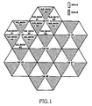
- the present invention will divide one cell into a total of six subsectors by dividing each individual sector into two subsectors. This division is illustrated in FIG. 1 .
- the present invention is not limited to the cell structure comprised of six subsectors. That is, the present invention can be applied in the same way to every cell structure in which one cell is comprised of a predetermined number of subsectors, the number being greater than six and a multiple of 2.
- the term "subsector” will be used herein for convenience of description, it will be construed that this has the same meaning as the term "sector” used previously.
- the subsector can be distinguished in a physical concept like the existing sector, or can be distinguished by two antenna beams within one physical sector. In order to distinguish the subsector in the physical concept, it is necessary to divide one cell into six sectors and allocate one antenna beam to each individual sector. Otherwise, it is necessary to divide one cell into three sectors and allocate two antenna beams to each individual sector. However, there is no difference in structure between the two cases to which the present invention is applied.
- each cell is comprised of three sectors and each of the sectors is divided into two subsectors. As described above, however, it would be obvious to those skilled in the art that the present invention can be applied in the same way even to the case where one cell is divided into six sectors.
- the present invention divides a full subcarrier band used in an OFDM/OFDMA system into two subcarrier regions having the same size.
- the two subcarrier regions will be called a "first subcarrier region” and a “second subcarrier region.”
- Downlink resources can be allocated to each individual subsector from any one of the first subcarrier region and the second subcarrier region.
- the subsectors are divided into subsectors allocated resources from the first subcarrier region and subsectors allocated resources from the second subcarrier region. Resources from the same subcarrier region should not be allocated to neighboring subsectors. This allocates resources from different subcarrier regions to the neighboring subsectors, thereby minimizing interference therebetween.
- the present invention selects subcarriers from a subcarrier region corresponding to 1/2 of the full subcarrier region and configures a subchannel with the selected subcarriers for each individual service zone. Selecting subchannels to configure a subchannel is a technique known to those skilled in the art, so a detailed description thereof will be omitted herein for simplicity.
- FIG. 1 is a diagram illustrating an exemplary cell structure proposed in the present invention, and downlink resources allocated for the cell structure. It is assumed in FIG. 1 that cells have an ideal type and the number of the cells is limited to seven.
- each cell is divided into a plurality of zones, e.g., zones A and B.
- the zones divided from the sectors become subsectors. Therefore, when one sector is divided into two zones, each cell is comprised of six subsectors.
- one of the two subsectors included in a sector is hatched, and another is not hatched, because downlink resources allocated to the individual subsectors are divided into two types.
- the downlink resources can be divided into downlink resources allocated to non-hatched subsectors denoted by 'zone A' (hereinafter referred to as a "first service zone") and downlink resources allocated to hatched subsectors denoted by 'zone B' (hereinafter referred to as a "second service zone").
- first service zone downlink resources allocated to hatched subsectors denoted by 'zone B'
- orthogonal downlink resources are allocated to the neighboring subsectors in the same cell.
- orthogonal indicates that there is no interference between the downlink resources.
- interference between the neighboring cells should also be considered when allocating the downlink resources.
- the hatched subsectors i.e., those in zone B, take the interference between the neighboring cells into consideration.
- the downlink resources should be allocated taking orthogonality into consideration. Therefore, the subsector #6 of the cell #1 is hatched but the subsector #3 of the cell #2 is not hatched. That is, the subsector #6 of the cell #1 belongs to the second service zone and the subsector #3 of the cell #2 belongs to the first service zone.
- FIG. 2 is a diagram illustrating an exemplary method for distributing downlink resources for the cell structure illustrated in FIG. 1 .
- the full subcarrier bandwidth used in the OFDM/OFDMA system is divided into a plurality of intervals having a predetermined bandwidth. It is assumed herein that the full subcarrier bandwidth includes M subcarriers and the predetermined bandwidth indicates an interval including m subcarriers.
- the full subcarrier band is divided into 16 intervals, by way of example. However, it would be obvious to those skilled in the art that the present invention can be applied in the same way to any subcarrier band structure in which the full subcarrier band is divided into a predetermined number of intervals, the number being a multiple of 2, other than sixteen.
- the 16 intervals are divided into two subcarrier regions having the same bandwidth of mx8. These will be called a "first subcarrier region” and a “second subcarrier region.”
- first subcarrier region is not-hatched and the second subcarrier region is hatched.
- the full subcarrier band the intervals belonging to the first subcarrier region and the intervals belonging to the second subcarrier region are alternately allocated. That is, the 16 intervals corresponding to the full subcarrier band are paired into 8 groups.
- a set of odd groups may be defined as the first subcarrier region and a set of even groups may be defined as the second subcarrier region.
- the downlink resources are allocated to the individual service zones illustrated in FIG. 1 . That is, among the service zones illustrated in FIG. 1 , the first service zone is allocated downlink resources from the subcarriers existing in the first subcarrier region in the full subcarrier band. Among the service zones shown in FIG. 1 , the second service zone is allocated downlink resources from the subcarriers existing in the second subcarrier region in the full subcarrier band. Therefore, the first service zone can use only 1/2 of the resources allocable in the OFDM/OFDMA system, and the second service zone can use only the remaining 1/2 resources.
- the present invention enables a detailed scheme for allocating downlink resources in subcarrier regions being mapped to the individual service zones to follow a common scheme for allocating downlink resources in the existing OFDM/OFDMA system. That is, in a particular subsector, a frequency allocation pattern is defined for each individual subchannel, and subcarriers selected from a corresponding subcarrier region are allocated as resources for the corresponding subchannel according to the defined frequency allocation pattern.
- the frequency allocation pattern can be defined in the same way for the subsectors belonging to the same service zone. That is, the frequency allocation pattern for each individual subchannel is defined in the same way for all subsectors belonging to the first service zone, and the frequency allocation pattern for each individual subchannel is defined in the same way for all subsectors belonging to the second service zone.
- the frequency allocation pattern for each individual subchannel can be defined in either the same way or different ways for all subsectors belonging to the first and second service zones.
- the frequency allocation pattern for each individual subchannel is defined in different ways for each subsector because it is effective to define different frequency allocation patterns in order to apply the load balancing scheme for individual subsectors.
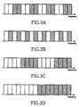
- FIGs. 3A through 3D are diagrams illustrating exemplary methods for dividing subcarrier regions to allocate downlink resources according to an embodiment of the present invention. It can be noted from FIGs. 3A through 3D that an embodiment of the present invention divides the full subcarrier region into two subcarrier regions having the same bandwidth.
- the full subcarrier region is divided into a plurality of intervals, and the intervals are designated as a first subcarrier region and a second subcarrier region in units of two intervals, by way of example.
- the full subcarrier region is divided into a plurality of intervals, and the intervals are designated as the first subcarrier region and the second subcarrier region in units of one interval, by way of example.
- the full subcarrier region is divided into a plurality of intervals, and the intervals are designated as the first subcarrier region and the second subcarrier region in units of four intervals, by way of example.
- the full subcarrier region is divided into a plurality of intervals, and the intervals are designated as the first subcarrier region and the second subcarrier region in units of half intervals, by way of example.
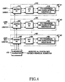
- FIG. 4 is a block diagram illustrating a transmission apparatus included in one cell according to an embodiment of the present invention. As described above, it is assumed in FIG. 4 that one cell is comprised of six subsectors. That is, the individual subsectors have their own unique transmission antennas.
- the transmission apparatus for a base station includes six transmitters 410 through 460 for transmitting user data for the individual subsectors, and a subcarrier allocator 470.
- the transmitters 410 through 460 include mappers 412, 422, and 462, IFFT blocks 414, 424, and 464, and parallel-to-serial (P/S) conversion and guard interval insertion blocks 416, 426, and 466, respectively.
- FIG. 4 user data separated for the individual subsectors is provided to their associated transmitters 410 through 460. It is noted that while FIG. 4 proposes a structure in which K users are transmitted by each of the transmitters 410 through 460, the number of users allocated to each individual transmitter is subject to change according to resource reallocation that will be described later.
- User data for user #1 through user #K is input to the first mapper 412
- user data for user #K+1 through user #2K is input to the second mapper 422
- user data for user #2K+1 through user #3K is input to the third mapper 462.
- the individual mappers 412, 422, and 462 map the user data provided for the individual users to the downlink subcarriers allocated for the individual users. That is, the mappers 412, 422, and 462 map the user data to input points of the IFFT blocks 414, 424, and 464 by the subcarriers allocated for the individual users.
- the subcarrier allocation for the mappers 412, 422, and 462 is achieved by the subcarrier allocator 470.
- the subcarrier allocator 470 allocates downlink subcarriers for the individual subsectors constituting one cell. For example, the subcarrier allocator 470 divides the full subcarrier band used in the OFDM/OFDMA system into a first subcarrier region and a second subcarrier region having the same bandwidth.
- the exemplary methods for dividing the full subcarrier band into the first subcarrier region and the second subcarrier region are illustrated in FIGs. 2 , and 3A through 3D . In FIGs. 2 , and 3A through 3D , the first subcarrier region is not hatched, and the second subcarrier region is hatched.
- mappers included in the odd transmitters are allocated subcarriers from the second subcarrier region, and mappers included in the even transmitters are allocated subcarriers from the first subcarrier region.
- the subcarrier allocation is achieved according to a predetermined subcarrier allocation pattern. The same subcarrier allocation pattern can be used for the mappers included in the odd transmitters, and the same subcarrier allocation pattern can be used even for the mappers included in the even transmitters.
- the odd transmitters cover odd subsectors among the subsectors included in one cell
- the even transmitters cover even subsectors among the subsectors included in one cell.
- the odd subsectors are hatched
- the even subsectors are not hatched.
- the subcarrier allocator 470 is provided with resource allocation information for the individual subsectors from the outside.
- the subcarrier allocator 470 measures a load at each subsector according to the resource allocation information, and then performs resource reallocation for balancing the loads of the subsectors.
- the resource reallocation can be achieved by changing the subcarrier allocation pattern for the subsectors or adjusting a beamwidth of the antennas covering the subsectors. That is, for the subsector being greater in load than other subsectors, the subcarrier allocator 470 may reduce the load by additionally allocating subcarriers or narrowing the beamwidth formed by the antenna.
- the subcarrier allocator 470 additionally allocates subcarriers for the subsector having the greater load
- the subcarrier allocator 470 withdraws the subcarriers allocated for subsectors neighboring the corresponding subsector, thereby maintaining the allocated subcarrier resources as a whole.
- the subcarrier allocator 470 narrows the beamwidth for the subsector having the greater load
- the subcarrier allocator widens a beamwidth of the subsectors neighboring the corresponding subsector.
- the user data mapped to the individual subcarriers by the mappers 412, 422, and 462 is provided to the IFFT blocks 414, 424, and 464 associated with the mappers 412, 422, and 462.
- the IFFT blocks 414, 424, and 464 perform IFFT modulation on the individual user data, and output time-domain user signals to the P/S conversion and guard interval insertion blocks 416, 426, and 466.
- the P/S conversion and guard interval insertion blocks 416, 426, and 466 convert parallel user signals into serial user signals, and insert guard intervals (or cyclic prefixes) in the serial user signals.
- the guard interval-inserted user signals are transmitted through transmission antennas Ant#1, Ant#2, ⁇ , Ant#6 associated with the P/S conversion and guard interval insertion blocks 416, 426, and 466.
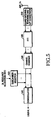
- FIG. 5 is a block diagram illustrating a reception apparatus for receiving user data transmitted through the allocated downlink resources according to an embodiment of the present invention.
- the reception apparatus for a mobile terminal includes a guard interval removing and serial-to-parallel (S/P) conversion block 510, an FFT block 520, a channel combiner 530, a subcarrier selector 550, and a demodulator 540.
- S/P serial-to-parallel
- user data transmitted through a downlink is received via a reception antenna ANT_Tx.
- the user data received via the reception antenna is provided to the guard interval removing and S/P conversion block 510.
- the guard interval removing and S/P conversion block 510 removes the guard interval inserted in the user data and converts the guard interval-removed user data into parallel user data.
- the guard interval-removed parallel user data is provided to the FFT block 520.
- the FFT block 520 performs FFT transform on the individual user data and outputs frequency-domain signals.
- the user data transformed into the frequency-domain signals are provided to the channel combiner 530.
- the channel combiner 530 combines the user data for individual channels.
- the subcarrier selector 550 receives downlink resource allocation information from a base station, and selects subcarriers allocated thereto according to the downlink resource allocation information.
- the subcarriers selected by the subcarrier selector 550 and the channel-combined user data are provided to the demodulator 540.
- the demodulator 540 demodulates the user data using the selected subcarriers.
- the present invention divides sectors constituting one cell into a plurality of subsectors in order to allocate uplink resources.
- the present invention will divide one cell into a total of six subsectors by dividing each individual sector into two subsectors, as is illustrated in FIG. 6 .
- the present invention is not limited to the cell structure comprised of six subsectors. That is, the present invention can be applied in the same way to every cell structure in which one cell is comprised of a predetermined number of subsectors, the number being greater than six and a multiple of 2.
- a first uplink resource allocation scheme additionally divides subcarrier regions divided for downlink resource allocation to allocate uplink resources.
- a second uplink resource allocation scheme allocates uplink resources using the intact subcarrier regions divided for downlink resource allocation.
- FIG. 6 is a diagram illustrating an exemplary cell structure proposed in the present invention for uplink resource allocation and an exemplary method for allocating uplink resources for the cell structure according to an embodiment of the present invention. It is assumed in FIG. 6 that cells have an ideal type and the number of the cells is limited to seven.
- each cell is comprised of six subsectors, and the individual subsectors are distinguished by different marks. This indicates that the individual subsectors are allocated different uplink resources. That is, the six subsectors correspond to six service zones denoted by 'zone A' through 'zone F'.
- the six service zones can be divided into a first service zone indicating a set of non-hatched service zones zone A, zone C, and zone E, and a second service zone indicating a set of hatched service zones zone B, zone D, and zone F.
- orthogonal uplink resources are allocated to neighboring subsectors in the same cell.
- the term "orthogonal" indicates that there is no interference between the uplink resources.
- interference between the neighboring cells should also be taken into account in the process of allocating the uplink resources.
- subsectors in different cells, to which the same subcarriers are allocated as uplink resources should be spaced apart as far as possible in order to minimize interference between the neighboring cells.
- subcarriers allocated to a subsector #6 of a cell #1 can be reused in a subsector #6 in a cell #2, which is spaced apart farthest from the subsector #6 of the cell #1. That is, the same subcarriers are reused as uplink resources for the subsectors having the same index in the respective cells. Therefore, it can be considered that the subsectors having the same index in the different cells belong to the same service zone.
- the first embodiment divides the full subcarrier band into a first subcarrier region and a second subcarrier region having the same size.
- the first embodiment divides the first subcarrier region into subintervals associated with the subsectors in the first service zone in the same cell, and allocates subcarriers selected in the divided subintervals as uplink resources for the subsectors in the first service zone.
- the first embodiment divides the second subcarrier region into subintervals associated with the subsectors in the second service zone in the same cell, and allocates subcarriers selected in the divided subintervals as uplink resources for the subsectors in the second service zone.
- FIG. 7 is a diagram illustrating an exemplary method for distributing uplink resources according to the first embodiment for uplink resource allocation.
- the full subcarrier bandwidth (including M subcarriers) used in the OFDM/OFDMA system is divided into two subcarrier regions, i.e., a "first subcarrier region" and a "second subcarrier region.”
- the first subcarrier region is not hatched and the second subcarrier region is hatched.
- the first subcarrier region and the second subcarrier region are each divided into a plurality of intervals having a predetermined bandwidth m.
- the first subcarrier region and the second subcarrier region are each divided into eight intervals, by way of example.
- the exemplary uplink resource allocation is equal to the downlink resource allocation in terms of the method for dividing the full subcarrier band.
- the individual intervals are additionally divided.
- the additionally divided intervals will be referred to as "subintervals").
- the number of the subintervals can be defined as a quotient obtained by dividing, by two, a positive multiple of the number of subsectors constituting one cell.
- one interval is divided into three subintervals, by way of example.
- the full subcarrier band allocated as uplink resources is comprised of six different types of subintervals.
- three subintervals are divided from the first subcarrier region, and the remaining three subintervals are divided from the second subcarrier region.
- the divided subintervals become subcarrier bands for the zone A through the zone F defined in FIG. 6 . Therefore, in FIG. 7 , six different types of subintervals are illustrated.
- the marks for distinguishing the subintervals are mapped to the marks for distinguishing the subsectors in one cell on a one-to-one basis. That is, the individual subsectors in FIG. 6 are allocated subcarriers from the subintervals having their own unique mark among the marks illustrated in FIG. 7 . By distinguishing the subcarrier regions (subintervals) that can be allocated as uplink resources for the individual subsectors in this manner, it is possible to prevent the interference between neighboring subsectors and also the interference from downlink resources used the neighboring cells.
- the full subcarrier band is divided into six different types of subintervals, by way of example.
- the full subcarrier band is divided into six types of subintervals, a particular user may use only one particular frequency band, making it difficult to obtain frequency diversity gain. Therefore, it is preferable to divide the full subcarrier band into 12 types of subintervals.
- the second embodiment for uplink resource allocation like the first embodiment, divides the full subcarrier band into a first subcarrier region and a second subcarrier region. Further, the second embodiment divides the total subchannels allocable in the first subcarrier region into as many subchannel groups as the number of subsectors belonging to the first service zone in one cell. This is applied in the same way even for the second subcarrier region. Therefore, it is preferable to determine the total number of channels as an integer that can be divided by the number of the subsectors.
- the total number of subchannels allocable in each of the first subcarrier region and the second subcarrier region is 60. Therefore, assuming that the total number of subchannels is 120 in this way, if the first and second service zones are each comprised of three subsectors, 20 subchannels (or a subchannel group) are allocated as uplink resources for each individual subsector.
- 60 subchannels allocated from the first subcarrier region are divided into three subchannel groups. That is, 1 st through 20 th subchannels are divided into a first subchannel group, 21 st through 40 th subchannels are divided into a second subchannel group, and 41 st through 60 th subchannels are divided into a third subchannel group.
- the 1 st through 20 th subchannels belonging to the first subchannel group are allocated as uplink resources for a subsector #1
- the 21 st through 40 th subchannels belonging to the second subchannel group are allocated as uplink resources for a subsector #3
- the 41 st through 60 th subchannels belonging to the third subchannel group are allocated as uplink resources for a subsector #5.
- 60 subchannels allocated from the second subcarrier region are divided into three subchannel groups. That is, 1 st through 20 th subchannels are divided into a first subchannel group, 21 st through 40 th subchannels are divided into a second subchannel group, and 41 st through 60 th subchannels are divided into a third subchannel group.
- the 1 st through 20 th subchannels belonging to the first subchannel group are allocated as uplink resources for a subsector #2
- the 21 st through 40 th subchannels belonging to the second subchannel group are allocated as uplink resources for a subsector #4
- the 41 st through 60 th subchannels belonging to the third subchannel group are allocated as uplink resources for a subsector #6.
- the uplink resource allocation scheme divides subchannels.
- the uplink resource allocation scheme can divide subcarrier allocation patterns used for configuring subchannels, and allocate the divided subcarrier allocation patterns for the individual subsectors.
- the subcarrier allocation patterns in the first subcarrier region and the subcarrier allocation patterns in the second subcarrier region can be determined as the same subcarrier allocation patterns.
- the subcarrier allocation patterns in the first subcarrier region and the subcarrier allocation patterns in the second subcarrier region can be determined as different subcarrier allocation patterns.
- the frequency reuse efficiency can be high because a frequency reuse distance is maximized at a frequency reuse factor of 1. That is, the frequency reuse is possible in a low-interference condition.
- a first load balancing scheme is a fixed beam scheme for redistributing downlink and uplink resources allocated for each individual subsector for load balancing. That is, the fixed beam scheme borrows resources from a neighboring beam if traffic is concentrated on a particular beam.
- a second load balancing scheme is an adjustable-beamwidth scheme for adjusting a service zone of each subsector. That is, the adjustable-beamwidth scheme induces softer handoff to a neighboring beam by reducing a width of a particular beam on which traffic is concentrated.
- the first load balancing scheme and the second load balancing scheme should be simultaneously performed to solve a problem that loads are concentrated on a particular subsector.
- FIG 8 is a diagram illustrating an exemplary method for balancing loads by redistributing uplink and downlink resources using the fixed beam scheme.
- FIG 8 illustrates an exemplary method for redistributing resources in one sector divided into two subsectors 820 and 840.
- antenna beams 810 and 830 are provided to the subsectors 820 and 840, respectively, and the antenna beams 810 and 830 are fixed to the same beamwidth.
- a load at the first subsector 820 is greater than a load at the second subsector 840.
- uplink and downlink resource allocation at the first subsector 820 and the second subsector 840 is performed by the resource allocation schemes proposed above.
- a load in the first subsector 820 is assumed to be equal to a load in the second subsector 840, so the same sized resources would be allocated for each of them.
- Users in the first subsector 820 and the second subsector 840 transmit/receive user data using the allocated uplink and downlink resources.
- an increase in load in the first subsector 820 causes a lack of resources allocated to the first subsector 820.
- the causes may include an increase in the number of users in the first subsector 820 and a user's demand for an improved quality-of-service (QoS).
- QoS quality-of-service
- This embodiment borrows resources allocated to the second subsector 840, i.e., a neighboring subsector, and additionally allocates the borrowed resources to the first subsector 820.
- the embodiment should take into account a load, i.e., the presence/absence of surplus resources, in the second subsector 840, instead of taking into account only the increase in load in the first subsector 820.
- a first transmission apparatus for generating a first antenna beam 810 covering the first subsector 820 performs an operation of periodically monitoring a load in the first subsector 820.
- the transmission apparatus can monitor the load depending on a use factor of resources allocated thereto. For example, the first transmission apparatus detects a lack of resources, if the used amount of resources allocated thereto is greater than a predetermined threshold.
- the first transmission apparatus sends a request for required resources to a second transmission apparatus (not shown), i.e., a neighboring transmission apparatus, upon detecting a lack of uplink or downlink resources due to an increase in its load.
- the second transmission apparatus generates a second antenna beam 830 covering the second subsector 840.
- the second transmission apparatus Upon receiving a resource reallocation request from the first transmission apparatus, the second transmission apparatus sends an approval for the use of surplus resources among the resources allocated thereto to the first transmission apparatus. That is, the second transmission apparatus provides the first transmission apparatus with information indicating subcarriers corresponding to the surplus resources. The first transmission apparatus transmits/receives user data using the resources, or subcarriers, reallocated from the second transmission apparatus.
- the resource redistribution may be performed by an upper layer, e.g., a base station controller (BSC), that controls resource management of the subsectors.
- BSC base station controller
- a subsector that requires additional resource allocation sends a resource allocation request to the upper layer.
- the upper layer withdraws resources of any subsector having surplus resources among the subsectors managed by itself, and reallocates the withdrawn resources to the subsector from which an additional resource allocation request was received.
- the foregoing resource redistribution reduces interference between beams in the same sector, but cannot prevent interference from neighboring beams of neighboring sectors or neighboring cells.
- the interference is insignificant compared with that occurring in the conventional scheme.
- FIG. 9 is a diagram illustrating an exemplary method for balancing loads by redistributing uplink and downlink resources using the adjustable-beamwidth scheme. More specifically, FIG. 9 illustrates an exemplary method for redistributing resources in one sector divided into two subsectors 920 and 940.
- antenna beams 910 and 930 are provided to the subsectors 920 and 940, respectively, and the antenna beams 910 and 930 are fixed to the same beamwidth.
- a load at the first subsector 920 is greater than a load at the second subsector 940.
- uplink and downlink resource allocation at the first subsector 920 and the second subsector 940 is performed by the resource allocation schemes proposed above.
- a load in the first subsector 920 is assumed to be equal to a load in the second subsector 940, so the same sized resources would be allocated for each of them.
- Users in the first subsector 920 and the second subsector 940 transmit/receive user data using the allocated uplink and downlink resources.
- an increase in load in the first subsector 920 causes a lack of resources allocated to the first subsector 920.
- the causes may include an increase in the number of users in the first subsector 920 and a user's demand for an improved QoS.
- a load reduction process will be processed.
- this embodiment decreases a width of the first antenna beam 910. The decrease in the width of the first antenna beam 910 narrows a corresponding service zone, thereby reducing the load.
- the width of the first antenna beam 910 is narrowed, some users may fail to transmit and receive user data with the first antenna beam 910. In this case, it is necessary to allow such users to be able to continuously transmit/receive user data with the second antenna beam 930, i.e., a neighboring antenna beam. In order to apply the foregoing method, it is necessary to take into account the increase in the load of the first subsector 920 and also the load of the second subsector 940.
- a first transmission apparatus for generating the first antenna beam 910 covering the first subsector 920 performs an operation of periodically monitoring a load in the first subsector 920.
- the transmission apparatus can monitor the load depending on a use factor of resources allocated thereto. For example, the first transmission apparatus detects a lack of resources, if the used amount of resources allocated thereto is greater than a predetermined threshold.
- the first transmission apparatus sends a request for widening the current antenna beamwidth to a second transmission apparatus (not shown), i.e., a neighboring transmission apparatus, upon detecting a lack of uplink or downlink resources due to an increase in its load.
- the second transmission apparatus generates a second antenna beam 930 covering the second subsector 940.
- the second transmission apparatus Upon receiving the request from the first transmission apparatus, the second transmission apparatus determines if it can widen the second antenna beam 930 taking its load into account. Widening the antenna beam is equivalent to increasing its load.
- the second transmission apparatus sends an approval for narrowing the antenna beamwidth to the first transmission apparatus, if it is determined that it can widen the second antenna beam 930. Thereafter, the second transmission apparatus widens the second antenna beam 930, thereby increasing its own load.
- the first transmission apparatus Upon receipt of the approval from the second transmission apparatus, the first transmission apparatus narrows the width of the first antenna beam 910, thereby reducing its own load.
- the user terminal that can no longer transmit and receive user data using the first transmission antenna beam 910, will attempt softer handoff to the second subsector 940 to transmit/receive user data using the second antenna beam 930. After the successful softer handoff, the user terminal can continue to transmit and receive user data using the second antenna beam 930.
- the resource redistribution may be performed by an upper layer, e.g., a BSC that takes charge of resource management of the subsectors.
- a subsector that has a great load, such that resources currently allocated thereto are insufficient sends a beamwidth adjust request to the upper layer.
- the upper layer sends a request for widening a beamwidth of a subsector having surplus resources among the neighboring subsectors of the subsector from which the beamwidth adjust request was received.
- the upper layer sends a beamwidth adjust approval to the subsector from which the beamwidth adjust request was received.
- a cross time slot (CTS) phenomenon occurs.
- Application of the present invention can moderate the CTS phenomenon by using subcarriers, which may serve as interference to each other, for the subsectors in neighboring cells, which are spaced apart farthest from each other.
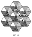
- FIG. 10 is a diagram illustrating a CTS phenomenon given for a description of an embodiment of the present invention. It is assumed in FIG. 10 that a cell #4 is transmitting user data through a downlink, and the other cells of cell #1, cell #2, cell #3, cell #5, cell #6, and cell #7 are transmitting user data through an uplink.
- main interference to a first terminal 1010 that is receiving user data through the downlink from a particular subsector in the cell #4 is caused by a terminal located in a neighboring subsector.
- the neighboring subsector includes subsectors included in the same cell #4, and subsectors included in neighboring cell #1, cell #3, and cell #7.
- the present invention allocates subcarriers in different subcarrier regions for the neighboring subsectors. Therefore, the first terminal 1010 can avoid interference caused by a terminal located in a neighboring sector of its subsector.
- interferences 1022, 1032, and 1042 occur, which are caused by terminals 1020, 1030, and 1040, located in subsectors allocated subcarriers from the same subcarrier region as the subsector in which the terminal 1010 is located among the subsectors included in the neighboring cell #1, cell #3, and cell #7.
- interferences do not act as considerable interferences to the first terminal 1010.
- the present invention can be applied to a system using a Space Division Multiple Access (SDMA) scheme (hereinafter referred to as an "SDMA system").
- SDMA system uses a plurality of narrow beams for a base station in order to increase its capacity.
- each of 6 subsectors included in one cell can be formed of a predetermined number K of beams.
- FIG. 11 is a diagram illustrating an exemplary method for applying the present invention to an SDMA system. It is assumed in FIG. 11 that each individual subsector is allocated M subcarriers and each subsector is formed of K narrow beams. Therefore, each individual narrow beam is allocated M/K subchannels. The subchannels allocated to each individual narrow beam are orthogonal with each other. The operation of allocating the subchannels to each individual narrow beam is performed using the above intact resource allocation scheme.
- Load control between beams formed in the same subsector is performed through variable channel borrowing.
- the variable channel borrowing can be implemented in the same way as the first embodiment of the load balancing scheme. In this case, there are two possible channel borrowings, i.e., channel borrowing between beams in the same subsector, and channel borrowing with a beam in a neighboring subsector.
- the neighboring subsector can be either a subsector located in the same cell or a subsector located in a neighboring cell.
- load balancing is performed through channel borrowing between neighboring beams as is denoted by a solid line.
- Such channel borrowing can be achieved because orthogonal subchannels are allocated for the beams in the same subsector.
- a channel is borrowed from a beam to which subchannels being orthogonal with its neighboring beams among the beams in the neighboring subsector.
- the neighboring beams can include the beams existing in the same cell as its own cell and also the beams forming a neighboring cell facing its own cell.
- subsectors included in the same cell as its own cell or subsectors facing its own cell there are two possible neighboring subsectors, i.e., subsectors included in the same cell as its own cell or subsectors facing its own cell. If a channel is to be borrowed from a subsector included in the same cell, a channel is borrowed from a beam in the same location as its own location in the subsector. Otherwise, if a channel is to be borrowed from a subsector facing its own cell, a channel is borrowed from a beam located in a diagonal direction from its own location in the subsector.
- the exemplary methods for borrowing channels from the neighboring subsectors are denoted by dotted line in FIG. 11 .
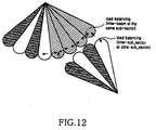
- FIG. 12 is a diagram illustrating another exemplary method for applying the present invention to an SDMA system. It is assumed in FIG. 12 that each individual subsector is allocated M subcarriers and each subsector is formed of K narrow beams, where K is an even number. In addition, M subchannels are divided into two orthogonal subgroups, and the orthogonal subgroups are sequentially allocated for the individual beams. That is, the subchannels are allocated for the individual beams in units of M/2 subchannels in an orthogonal manner. Allocating the subchannels to each individual narrow beam is performed using the above intact resource allocation scheme.
- load balancing is performed through channel borrowing between neighboring beams, as is denoted by a solid line.
- Such channel borrowing can be achieved because M subchannels are divided into two subgroups and subchannels in different subgroups are allocated for neighboring beams in the same subsector. Therefore, the neighboring beams are orthogonal with each other.
- a channel is borrowed from a particular beam in subsectors in the same cell or from a facing beam.
- the facing beam belongs to a cell neighboring its own cell. Therefore, a beam located in a boundary of a subsector can borrow a channel from both a beam defining a boundary with itself and a beam facing itself.
- the exemplary methods for borrowing channels from the neighboring subsectors are denoted by dotted line in FIG. 12 .
- the load control between multiple beams in the same subsector is performed through variable channel borrowing.
- the load balancing scheme through channel borrowing between neighboring sectors in the same cell or neighboring cells, borrows subchannels being orthogonal with allocated subchannels for the facing beams in the neighboring cell from the neighboring subsector in the same cell or the facing subsector in the neighboring cell.
- the resources borrowed from the neighboring beam or neighboring subsector are necessarily allocated to a terminal having a good path gain or channel condition, thereby reducing interference between the borrowed channels.
- the foregoing novel sectorization and resource allocation can:
Landscapes
- Engineering & Computer Science (AREA)
- Computer Networks & Wireless Communication (AREA)
- Signal Processing (AREA)
- Mobile Radio Communication Systems (AREA)
Claims (16)
- Verfahren zum Vergeben von Ressourcen für einzelne Sektoren in einem mobilen Kommunikationssystem, in dem orthogonales Frequenzmultiplexen, OFDM, angewendet wird, wobei das Verfahren folgende Schritte umfasst:Unterteilen eines vollständigen Subträgerbandes in einen ersten Subträgerbereich und einen zweiten Subträgerbereich gleicher Größe;Vergeben von Subträgern, die aus dem ersten Subträgerbereich gewählt werden, auf der Basis eines ersten Subträger-Vergabemusters als Downlink-Ressourcen für Sektoren in einer ersten Dienstzone aus einer Vielzahl von Sektoren, die in einer Zelle enthalten sind; undVergeben von Subträgern, die aus dem zweiten Subträgerbereich gewählt werden, auf der Basis eines Zweiten Subträger-Vergabemusters als Downlink-Ressourcen für Sektoren in einer zweiten Dienstzone;gekennzeichnet durch,sofern eine Auslastung in einem der Sektoren größer ist als eine Auslastung in einem benachbarten Sektor, Verschmälern einer ersten Antennenstrahlbreite, die den einen der Sektoren bildet, und verbreitern einer zweiten Antennenstrahlbreite, die den benachbarten Sektor bildet, sowie Freigeben von Ressourcen, die für den benachbarten Sektor vergeben waren, und anschließendes Neuvergeben der freigegebenen Ressourcen als Ressourcen für den einen der Sektoren,wobei, wenn es wenigstens einem Benutzer durch Verschmälern der ersten Antennenstrahlbreite nicht gelingt, Benutzerdaten zu senden und zu empfangen, der wenigstens eine Benutzer Benutzerdaten mit dem zweiten Antennenstrahl sendet und empfängt, um fortwährend Benutzerdaten zu senden und zu empfangen,wobei die Zelle eine vorbestimmte Anzahl von Sektoren enthält, die vorbestimmte Anzahl ein Vielfaches von 2 und wenigstens gleich 6 ist und die Sektoren in der ersten Dienstzone an die Sektoren in der zweiten Dienstzone grenzen.
- Verfahren nach Anspruch 1, bei dem der erste Subträgerebereich und der zweite Subträgerbereich in eine Vielzahl von Subträgerbänder unterteilt werden, die eine vorbestimmte Größe haben.
- Verfahren nach Anspruch 1, bei dem der erste Subträgerbereich und der zweite Subträgerbereich einheitlich über das gesamte Subträgerband verteilt werden.
- Verfahren nach Anspruch 1, bei dem Subträger, die aus unterschiedlichen Subträgerbereichen gewählt werden, als Downlink-Ressourcen für Sektoren vergeben werden, die in unterschiedlichen Zellen enthalten sind, jedoch aneinander grenzen.
- Verfahren nach Anspruch 1, bei dem der erste Subträgerbereich in Subintervalle unterteilt wird, die auf Sektoren in der ersten Dienstzone abgestimmt sind, und Subträger, die aus den unterteilten Subintervallen gewählt werden, als Uplink-Ressourcen für die Sektoren in der ersten Dienstzone vergeben werden.
- Verfahren nach Anspruch 5, bei dem der zweite Subträgerbereich in Subintervalle unterteilt wird, die auf Sektoren in der zweiten Dienstzone abgestimmt sind, und Subträger, die aus den unterteilten Subintervallen gewählt werden, als Uplink-Ressourcen für die Sektoren in der zweiten Dienstzone vergeben werden.
- Verfahren nach Anspruch 6, bei dem die freigegebenen Ressourcen Uplink-Ressourcen sind.
- Verfahren nach Anspruch 1, bei dem die freigegebenen Ressourcen Downlink-Ressourcen sind.
- Sendegerät zum Senden von Benutzerdaten für einzelne Sektoren in einem mobilen Kommunikationssystem, in dem orthogonales Frequenzmultiplexen, OFDM, angewendet wird, wobei das Gerät enthält:eine Subträger-Vergabeeinrichtung, die dazu eingerichtet ist, ein vollständiges Subträgerband in einen ersten Subträgerbereich und einen zweiten Subträgerbereich gleicher Größe zu unterteilen, Subträger, die aus dem ersten Subträgerbereich gewählt werden, auf der Basis eines ersten Subträger-Vergabemusters als Downlink-Ressourcen für Sektoren in einer ersten Dienstzone zu vergeben und Subträger, die aus dem zweiten Subträgerbereich gewählt werden, auf der Basis eines zweiten Subträger-Vergabemusters als Downlink-Ressourcen für Sektoren in einer zweiten Service-Zone zu vergeben, dadurch gekennzeichnet, dass, wenn eine Auslastung in einem der Sektoren größer ist als eine Auslastung in einem benachbarten Sektor, sie eine erste Antennenstrahlbreite verschmälert, die den einen der Sektoren bildet, und eine zweite Antennenstrahlbreite verbreitert, die den benachbarten Sektor bildet, und Ressourcen freigibt, die für den benachbarten Sektor zugewiesen waren, und anschließend die freigegebenen Ressourcen als Ressourcen für den einen der Sektoren erneut vergibt;wobei in Erwiderung darauf, dass es nicht gelingt, Benutzerdaten mit dem ersten Antennenstrahl durch Verschmälerung der ersten Antennenstrahlbreite zu senden und zu empfangen, die Sendevorrichtung dazu eingerichtet ist, Benutzerdaten mit dem zweiten Antennenstrahl zu senden und zu empfangen, um fortwährend Benutzerdaten zu senden und zu empfangen,eine Vielzahl von Abstimmungseinrichtungen (412, 422, 462), die dazu eingerichtet sind, Benutzerdaten zu empfangen, die für die einzelnen Sektoren zu senden sind, und die Benutzerdaten auf die Subträger entsprechend den Downlink-Ressourcen abzustimmen, die für die einzelnen Sektoren zugeordnet sind;eine Vielzahl von Blöcken (414, 424, 464) für eine inverse, schnelle Fouriertransformation, IFFT, die dazu eingerichtet sind, die Benutzerdaten, die auf die einzelnen Subträger abgestimmt sind, in Zeitdomänen-Benutzersignale umzuwandeln; undeine Vielzahl von Schutzintervall-Einfügeeinrichtungen (416, 426, 466), die dazu eingerichtet sind, ein Schutzintervall in jedes der Zeitdomänen-Benutzersignale einzufügen und die Benutzersignale, in die ein Schutzintervall eingefügt ist, über Sendeantennen zu senden, die den einzelnen Sektoren zugeordnet sind;wobei die Sektoren in der ersten Dienstzone nicht angrenzende Sektoren unter den Sektoren haben und die Sektoren in der zweiten Dienstzone die übrigen Sektoren mit Ausnahme der Sektoren in der ersten Dienstzone enthalten.
- Sendegerät nach Anspruch 9, bei dem der erste Subträgerbereich und der zweite Subträgerbereich in eine Vielzahl von Subträgerbändern unterteilt sind, die eine vorbestimmte Größe haben.
- Sendegerät nach Anspruch 10, bei dem der erste Subträgerbereich und der zweite Subträgerbereich gleichmäßig über das vollständige Subträgerband verteilt sind.
- Sendegerät nach Anspruch 9, bei dem die Subträger-Vergabeeinrichtung (470) dazu eingerichtet ist, Subträger, die aus unterschiedlichen Subträgerbereichen gewählt sind, als Downlink-Ressourcen für Sektoren zu vergeben, die in unterschiedlichen Zellen enthalten, jedoch einander benachbart sind.
- Sendegerät nach Anspruch 9, bei dem die Subträger-Vergabeeinrichtung (470) dazu eingerichtet ist, den ersten Subträgerbereich in Subintervalle zu unterteilen, die auf Sektoren in der ersten Dienstzone abgestimmt sind, und Subträger, die aus den unterteilten Subintervallen gewählt sind, als Uplink-Ressourcen für die Sektoren in der ersten Dienstzone zu vergeben.
- Sendegerät nach Anspruch 13, bei dem die Subträger-Vergabeeinrichtung (470) dazu eingerichtet ist, den zweiten Subträgerbereich in Subintervalle zu unterteilen, die auf Sektoren in der ersten Dienstzone abgestimmt sind, und Subträger, die aus den unterteilten Subintervallen gewählt sind, als Uplink-Ressourcen für die Sektoren in der zweiten Dienstzone zu vergeben.
- Sendegerät nach Anspruch 14, bei dem die freigegebenen Ressourcen Uplink-Ressourcen sind.
- Sendegerät nach Anspruch 9, bei dem die freigegebenen Ressourcen Downlink-Ressourcen sind.
Applications Claiming Priority (1)
| Application Number | Priority Date | Filing Date | Title |
|---|---|---|---|
| KR1020040097135A KR100957318B1 (ko) | 2004-11-24 | 2004-11-24 | 다중 반송파 시스템에서의 자원할당 방법 및 장치 |
Publications (2)
| Publication Number | Publication Date |
|---|---|
| EP1662825A1 EP1662825A1 (de) | 2006-05-31 |
| EP1662825B1 true EP1662825B1 (de) | 2012-02-01 |
Family
ID=35892583
Family Applications (1)
| Application Number | Title | Priority Date | Filing Date |
|---|---|---|---|
| EP05025686A Expired - Lifetime EP1662825B1 (de) | 2004-11-24 | 2005-11-24 | Verfahren zur Zuweisung von Betriebsmitteln in einem Mehrträgersystem und dieses benutzendes Übertragungsvorrichtung |
Country Status (3)
| Country | Link |
|---|---|
| US (1) | US7593420B2 (de) |
| EP (1) | EP1662825B1 (de) |
| KR (1) | KR100957318B1 (de) |
Families Citing this family (51)
| Publication number | Priority date | Publication date | Assignee | Title |
|---|---|---|---|---|
| EP1814345A1 (de) * | 2006-01-26 | 2007-08-01 | Mitsubishi Electric Information Technology Centre Europe B.V. | Verfahren zur Signalübertragung in Sektoren durch eine Basisstation in einem drahtlosen Telekommunikationsnetzwerk |
| US20070177545A1 (en) * | 2006-01-30 | 2007-08-02 | Natarajan Kadathur S | System and method for allocating sub-channels in a network |
| KR101035083B1 (ko) * | 2006-04-26 | 2011-05-19 | 재단법인서울대학교산학협력재단 | 다중 셀 통신 시스템에서 자원 이용 방법 및 시스템 |
| EP1868400B1 (de) * | 2006-06-13 | 2008-08-13 | Alcatel Lucent | Verfahren zum Zuteilen von Funkbetriebsmitteln eines zellularen Kommunikationsnetzwerks |
| JP4793569B2 (ja) * | 2006-06-19 | 2011-10-12 | 日本電気株式会社 | 帯域割当方法および無線通信システム |
| KR100745086B1 (ko) * | 2006-08-21 | 2007-08-01 | 한국전자통신연구원 | Ofdm 기반 이동통신 시스템에서 자원 할당 방법 |
| KR101023833B1 (ko) * | 2006-08-31 | 2011-03-22 | 아주대학교산학협력단 | 통신 시스템에서 자원 이용 시스템 및 방법 |
| CN101146343B (zh) * | 2006-09-13 | 2010-05-19 | 联想(北京)有限公司 | 一种移动通信系统中的带宽资源分配方法及装置 |
| CN100591151C (zh) | 2006-09-22 | 2010-02-17 | 联想(北京)有限公司 | 蜂窝网络及其实现广播通信和数据通信的方法 |
| JP2008160720A (ja) * | 2006-12-26 | 2008-07-10 | Fujitsu Ltd | 複数のセクタ対応の送信部を備えた無線基地局及び複数のセクタ用の信号の送信方法 |
| EP2104370B1 (de) | 2007-01-09 | 2020-08-12 | Sun Patent Trust | Funkkommunikations-basisstationsvorrichtung und steuersignalzuweisungsverfahren dafür |
| KR20080089728A (ko) * | 2007-04-02 | 2008-10-08 | 엘지전자 주식회사 | 다중 부 반송파 시스템에서의 부 반송파 간격 적용 방법 및이를 지원하는 이동 단말 |
| US20080233966A1 (en) * | 2007-03-22 | 2008-09-25 | Comsys Communication & Signal Processing Ltd. | Resource allocation apparatus and method in an orthogonal frequency division multiple access communication system |
| US7706323B2 (en) * | 2007-05-02 | 2010-04-27 | Alvarion Ltd. | Wireless communications in a multi-sector network |
| EP2152013A1 (de) * | 2007-05-31 | 2010-02-10 | Nec Corporation | Basisstation, funkkommunikationssystem, frequenzbandsteuerungsverfahren |
| US8130780B2 (en) | 2007-06-15 | 2012-03-06 | Futurewei Technologies, Inc. | Method and apparatus for assigning resources in a wireless system with multiple regions |
| US8614985B2 (en) * | 2007-06-15 | 2013-12-24 | Futurewei Technologies, Inc. | Method and apparatus for sharing a group resource in a wireless SDMA system |
| US8073085B1 (en) * | 2007-07-07 | 2011-12-06 | Redpine Signals, Inc. | Analog to digital converter bit width and gain controller for a wireless receiver |
| US9544911B2 (en) * | 2007-08-10 | 2017-01-10 | Futurewei Technologies, Inc. | System and method for assigning communications resources in a wireless communications system |
| US8526371B2 (en) | 2007-08-13 | 2013-09-03 | Qualcomm Incorporated | Frequency diverse transmissions in a wireless communication system |
| EP2811803B1 (de) * | 2007-11-30 | 2019-09-25 | Alcatel Lucent | Verfahren zur Durchführung der Ressourcenzuweisung in einem drahtlosen Kommunikationsnetzwerk und Basisstation |
| KR100930998B1 (ko) * | 2008-01-28 | 2009-12-10 | 연세대학교 산학협력단 | Mimo-ofdm 시스템과 상기 mimo-ofdm시스템에서 사용자 단말을 위한 부반송파 할당 방법 및자원 할당 방법 |
| US8054790B2 (en) | 2008-05-05 | 2011-11-08 | Alcatel Lucent | Frequency mapping for a wireless communication system |
| EP2129178A1 (de) * | 2008-05-06 | 2009-12-02 | Alcatel Lucent | Verfahren zur Zuweisung von Frequenzunterkanälen auf einer Luftschnittstelle eines drahtlosen Kommunikationssystems und entsprechendes Funkressourcenzuweisungsmodul |
| US8194623B2 (en) * | 2008-06-27 | 2012-06-05 | Ntt Docomo, Inc. | Evolving-type user resource structure/channelization with enhanced diversity for OFDMA based time-varying channels |
| US9078138B2 (en) * | 2008-11-20 | 2015-07-07 | Board Of Regents, The University Of Texas System | Interference management and decentralized channel access schemes in hotspot-aided cellular networks |
| KR101151048B1 (ko) * | 2008-11-25 | 2012-06-01 | 한국전자통신연구원 | 부분 주파수 재사용 기법을 적용한 지상보조장치를 포함하는 이동 위성 통신 장치 및 방법 |
| US8243648B2 (en) * | 2008-12-19 | 2012-08-14 | Intel Corporation | Spatial reuse techniques with wireless network relays |
| EP2374296B8 (de) * | 2008-12-23 | 2012-11-21 | Telecom Italia S.p.A. | Verfahren zur dimensionierung von funkzugangsnetzen, entsprechendes system und computerprogrammprodukt |
| WO2010101385A2 (ko) * | 2009-03-02 | 2010-09-10 | 엘지전자 주식회사 | 무선 통신 시스템에서 서브밴드/미니밴드 맵핑 방법 및 이를 위한 장치 |
| US8218420B2 (en) * | 2009-03-26 | 2012-07-10 | Ntt Docomo, Inc. | Non-cyclic evolving-type user resource structure for OFDMA based system with null guard tones |
| US20110053628A1 (en) * | 2009-08-27 | 2011-03-03 | Electronics And Telecommunications Research Institute | Service providing system and method in satellite communication system |
| KR101336881B1 (ko) * | 2009-08-27 | 2013-12-04 | 한국전자통신연구원 | 위성 통신 시스템에서 서비스 제공 시스템 및 방법 |
| JP4740365B2 (ja) | 2009-10-26 | 2011-08-03 | シャープ株式会社 | 移動局装置、基地局装置、無線通信システム、通信制御方法、通信制御プログラム、及びプロセッサ |
| US8886755B1 (en) * | 2009-12-09 | 2014-11-11 | Marvell International Ltd. | Method and apparatus for facilitating simultaneous transmission from multiple stations |
| KR20120116016A (ko) * | 2010-02-12 | 2012-10-19 | 알까뗄 루슨트 | 중계 보조 셀룰러 네트워크에서의 셀간 간섭 조정을 위한 장비 및 방법 |
| JP5073021B2 (ja) * | 2010-07-28 | 2012-11-14 | 株式会社エヌ・ティ・ティ・ドコモ | クラスタ内協調及びクラスタ間干渉回避方法、無線通信システム、集約局及び無線基地局 |
| US8824267B2 (en) * | 2010-08-13 | 2014-09-02 | Telefonaktiebolaget L M Ericsson (Publ) | Systems and methods for transmit diversity for DFT precoded channels |
| KR101286586B1 (ko) | 2011-10-18 | 2013-07-22 | 한국과학기술원 | 효율적 자원할당을 위한 bdma 기반 하이브리드 통신망 시스템 및 그 제공방법 |
| EP3761518A1 (de) * | 2013-07-11 | 2021-01-06 | Interdigital Patent Holdings, Inc. | Verfahren und vorrichtung zur unterstützung von sektorisierungskoordination |
| WO2015010286A1 (zh) * | 2013-07-24 | 2015-01-29 | 华为技术有限公司 | 对频谱资源进行频分复用的方法、装置及系统 |
| CN105792360B (zh) * | 2014-12-24 | 2020-02-14 | 中兴通讯股份有限公司 | 超级小区下资源分配的方法及装置 |
| WO2016123551A1 (en) | 2015-01-30 | 2016-08-04 | C&D Zodiac, Inc. | Ceiling panel assembly and mounting system therefor |
| KR101784595B1 (ko) | 2016-01-15 | 2017-10-11 | 한국과학기술원 | Bdma 기반 통신시스템에서 자원 재사용 방법 |
| WO2017122882A1 (ko) * | 2016-01-15 | 2017-07-20 | 한국과학기술원 | Bdma 기반 통신시스템에서 자원 재사용 방법 |
| HK1257408A1 (zh) | 2016-05-24 | 2019-10-18 | Oppo广东移动通信有限公司 | 用於消除小区间干扰的方法和装置 |
| JP2019530994A (ja) * | 2016-08-17 | 2019-10-24 | グァンドン オッポ モバイル テレコミュニケーションズ コーポレーション リミテッドGuangdongoppo Mobile Telecommunications Corp., Ltd. | リソース割り当て方法及び装置 |
| EP3468248B1 (de) * | 2016-10-14 | 2020-10-07 | Guangdong Oppo Mobile Telecommunications Corp., Ltd. | Kommunikationsverfahren und -vorrichtung |
| CN110192353B (zh) * | 2017-01-18 | 2022-02-18 | 瑞典爱立信有限公司 | 网络节点及调度网络节点与无线设备之间的传输的方法 |
| CN109392047B (zh) * | 2017-08-10 | 2021-03-23 | 普天信息技术有限公司 | 正交频分复用系统中子带切换的指示方法 |
| KR102463661B1 (ko) * | 2020-12-08 | 2022-11-04 | 한국전자통신연구원 | 무선 통신 시스템에서의 변조 및 복조 방법 및 장치 |
Citations (1)
| Publication number | Priority date | Publication date | Assignee | Title |
|---|---|---|---|---|
| EP0837523A2 (de) * | 1996-10-18 | 1998-04-22 | Kabushiki Kaisha Toshiba | Adaptive Antenne |
Family Cites Families (10)
| Publication number | Priority date | Publication date | Assignee | Title |
|---|---|---|---|---|
| US4144496A (en) * | 1976-03-17 | 1979-03-13 | Harris Corporation | Mobile communication system and method employing frequency reuse within a geographical service area |
| US5073971A (en) * | 1989-09-05 | 1991-12-17 | Motorola, Inc. | Cellular radiotelephone communications system |
| US5276907A (en) * | 1991-01-07 | 1994-01-04 | Motorola Inc. | Method and apparatus for dynamic distribution of a communication channel load in a cellular radio communication system |
| EP1336260A4 (de) * | 2000-11-24 | 2009-01-21 | Sk Telecom Co Ltd | Vorrichtung zur verteilung/zusammenührung eines mehrfachstrahls in einem mobilenkommunikationssystem |
| WO2002049385A2 (en) * | 2000-12-15 | 2002-06-20 | Broadstorm Telecommunications, Inc. | Multi-carrier communications with adaptive cluster configuration and switching |
| US6907246B2 (en) * | 2001-11-20 | 2005-06-14 | Navini Networks, Inc. | Method and system for reducing wireless multi-cell interferences through segregated channel assignments and segregated antenna beams |
| KR100490324B1 (ko) * | 2003-01-24 | 2005-05-17 | 주식회사 매커스 | 무선 셀룰러 통신망 시스템에서 사용되는 송신방법 및송신장치 |
| JP3898681B2 (ja) * | 2003-09-30 | 2007-03-28 | 株式会社東芝 | 携帯端末、通信システムおよび通信方法 |
| US7771777B2 (en) * | 2004-06-14 | 2010-08-10 | Acushnet Company | Apparatus and method for inspecting golf balls using infrared radiation |
| US7372913B2 (en) * | 2004-07-22 | 2008-05-13 | Qualcomm Incorporated | Pilot tones in a multi-transmit OFDM system usable to capture transmitter diversity benefits |
-
2004
- 2004-11-24 KR KR1020040097135A patent/KR100957318B1/ko not_active Expired - Fee Related
-
2005
- 2005-11-24 EP EP05025686A patent/EP1662825B1/de not_active Expired - Lifetime
- 2005-11-25 US US11/286,728 patent/US7593420B2/en active Active
Patent Citations (1)
| Publication number | Priority date | Publication date | Assignee | Title |
|---|---|---|---|---|
| EP0837523A2 (de) * | 1996-10-18 | 1998-04-22 | Kabushiki Kaisha Toshiba | Adaptive Antenne |
Also Published As
| Publication number | Publication date |
|---|---|
| US7593420B2 (en) | 2009-09-22 |
| KR100957318B1 (ko) | 2010-05-12 |
| KR20060057937A (ko) | 2006-05-29 |
| EP1662825A1 (de) | 2006-05-31 |
| US20060109865A1 (en) | 2006-05-25 |
Similar Documents
| Publication | Publication Date | Title |
|---|---|---|
| EP1662825B1 (de) | Verfahren zur Zuweisung von Betriebsmitteln in einem Mehrträgersystem und dieses benutzendes Übertragungsvorrichtung | |
| KR101067772B1 (ko) | 직교 주파수 분할 다중화 방식에 적용되는 부반송파 할당방법 | |
| EP1408710B1 (de) | Vorrichtung und Verfahren zur Zuweisung von Ressourcen einer virtuellen Zelle in einem OFDM-Mobilkommunikationssystem | |
| KR100617729B1 (ko) | 셀룰러 통신 시스템에서 다중 주파수 재사용율 기반의 주파수 자원 할당 시스템 및 방법 | |
| KR100575434B1 (ko) | 직교주파수 분할 다중 접속 기반 셀룰러 시스템에서의 자원 공간 분할 및 물리 채널 할당 방법 | |
| US7764662B2 (en) | System and method for allocating frequency resource in a multicell communication system | |
| KR100965338B1 (ko) | Ofdm 셀룰러 환경에서 셀간 간섭 저감을 위한부반송파 할당방법 | |
| CN1902972B (zh) | 用于无线通信系统的分层重用 | |
| CN1943143B (zh) | 在使用正交频分多址方案的通信系统中控制传输功率的装置和方法 | |
| US8009549B2 (en) | Carrier allocation method in multi cell orthogonal frequency division multiple access system | |
| US20050265222A1 (en) | Method for inter-cell interference coordination with power planning for OFDM mobile communication system | |
| CN101507159B (zh) | 发送装置及通信方法 | |
| WO2005125262A1 (en) | Intra-cell common reuse for a wireless communication system | |
| JP2006515141A (ja) | 通信システムの同一チャネル干渉を低減させる方法及び装置 | |
| KR20080090918A (ko) | 직교 주파수 분할 다중 접속 방식의 분산 안테나시스템에서 부반송파 할당을 위한 서브 셀 선택 장치 및방법 | |
| WO2008020623A1 (en) | Wireless communication base station device and control channel arranging method | |
| KR20090032628A (ko) | 직교 주파수 분할 다중 방식의 분산 안테나 시스템에서무선 자원 할당 방법 및 장치 | |
| KR101235670B1 (ko) | 무선 통신 시스템의 무선 인터페이스에 대한 주파수 서브채널들을 할당하기 위한 방법 및 대응하는 라디오 리소스 할당 모듈 | |
| CN101193086B (zh) | 一种正交频分复用系统频率规划的方法 | |
| KR100747600B1 (ko) | 직교 주파수 분할 다중접속 시스템을 위한 주파수 재사용율분할 방식에 기반을 둔 동적 자원 할당 방법 및 그를 위한프레임 전송 방법 | |
| KR100477471B1 (ko) | 고속 무선 통신에서의 다중 접속 방법 | |
| KR20080096966A (ko) | 직교 주파수 분할 다중 접속 방식의 분산 안테나시스템에서 주파수 재사용율 기반의 부반송파 할당 방법 | |
| Lee et al. | Virtual-cell frequency reuse scheme to support seamless service in femtocell environments | |
| KR20060056141A (ko) | 직교 주파수 다중 접속 방식의 무선 통신 시스템에서자원할당 방법 및 시스템 |
Legal Events
| Date | Code | Title | Description |
|---|---|---|---|
| PUAI | Public reference made under article 153(3) epc to a published international application that has entered the european phase |
Free format text: ORIGINAL CODE: 0009012 |
|
| 17P | Request for examination filed |
Effective date: 20051125 |
|
| AK | Designated contracting states |
Kind code of ref document: A1 Designated state(s): AT BE BG CH CY CZ DE DK EE ES FI FR GB GR HU IE IS IT LI LT LU LV MC NL PL PT RO SE SI SK TR |
|
| AX | Request for extension of the european patent |
Extension state: AL BA HR MK YU |
|
| 17Q | First examination report despatched |
Effective date: 20060804 |
|
| AKX | Designation fees paid |
Designated state(s): DE FI FR GB IT SE |
|
| REG | Reference to a national code |
Ref country code: DE Ref legal event code: R079 Ref document number: 602005032476 Country of ref document: DE Free format text: PREVIOUS MAIN CLASS: H04Q0007360000 Ipc: H04W0016020000 |
|
| RIC1 | Information provided on ipc code assigned before grant |
Ipc: H04W 16/02 20090101AFI20110421BHEP |
|
| GRAP | Despatch of communication of intention to grant a patent |
Free format text: ORIGINAL CODE: EPIDOSNIGR1 |
|
| GRAS | Grant fee paid |
Free format text: ORIGINAL CODE: EPIDOSNIGR3 |
|
| GRAA | (expected) grant |
Free format text: ORIGINAL CODE: 0009210 |
|
| AK | Designated contracting states |
Kind code of ref document: B1 Designated state(s): DE FI FR GB IT SE |
|
| REG | Reference to a national code |
Ref country code: GB Ref legal event code: FG4D |
|
| REG | Reference to a national code |
Ref country code: DE Ref legal event code: R096 Ref document number: 602005032476 Country of ref document: DE Effective date: 20120329 |
|
| REG | Reference to a national code |
Ref country code: SE Ref legal event code: TRGR |
|
| RAP2 | Party data changed (patent owner data changed or rights of a patent transferred) |
Owner name: SAMSUNG ELECTRONICS CO., LTD. |
|
| PLBE | No opposition filed within time limit |
Free format text: ORIGINAL CODE: 0009261 |
|
| STAA | Information on the status of an ep patent application or granted ep patent |
Free format text: STATUS: NO OPPOSITION FILED WITHIN TIME LIMIT |
|
| 26N | No opposition filed |
Effective date: 20121105 |
|
| REG | Reference to a national code |
Ref country code: DE Ref legal event code: R097 Ref document number: 602005032476 Country of ref document: DE Effective date: 20121105 |
|
| REG | Reference to a national code |
Ref country code: FR Ref legal event code: PLFP Year of fee payment: 12 |
|
| REG | Reference to a national code |
Ref country code: FR Ref legal event code: PLFP Year of fee payment: 13 |
|
| REG | Reference to a national code |
Ref country code: FR Ref legal event code: PLFP Year of fee payment: 14 |
|
| PGFP | Annual fee paid to national office [announced via postgrant information from national office to epo] |
Ref country code: FI Payment date: 20191021 Year of fee payment: 15 Ref country code: SE Payment date: 20191022 Year of fee payment: 15 Ref country code: DE Payment date: 20191021 Year of fee payment: 15 |
|
| PGFP | Annual fee paid to national office [announced via postgrant information from national office to epo] |
Ref country code: IT Payment date: 20191121 Year of fee payment: 15 Ref country code: FR Payment date: 20191023 Year of fee payment: 15 |
|
| PGFP | Annual fee paid to national office [announced via postgrant information from national office to epo] |
Ref country code: GB Payment date: 20191023 Year of fee payment: 15 |
|
| REG | Reference to a national code |
Ref country code: DE Ref legal event code: R119 Ref document number: 602005032476 Country of ref document: DE |
|
| REG | Reference to a national code |
Ref country code: FI Ref legal event code: MAE |
|
| REG | Reference to a national code |
Ref country code: SE Ref legal event code: EUG |
|
| GBPC | Gb: european patent ceased through non-payment of renewal fee |
Effective date: 20201124 |
|
| PG25 | Lapsed in a contracting state [announced via postgrant information from national office to epo] |
Ref country code: FI Free format text: LAPSE BECAUSE OF NON-PAYMENT OF DUE FEES Effective date: 20201124 |
|
| PG25 | Lapsed in a contracting state [announced via postgrant information from national office to epo] |
Ref country code: SE Free format text: LAPSE BECAUSE OF NON-PAYMENT OF DUE FEES Effective date: 20201125 |
|
| PG25 | Lapsed in a contracting state [announced via postgrant information from national office to epo] |
Ref country code: IT Free format text: LAPSE BECAUSE OF NON-PAYMENT OF DUE FEES Effective date: 20201124 Ref country code: FR Free format text: LAPSE BECAUSE OF NON-PAYMENT OF DUE FEES Effective date: 20201130 |
|
| PG25 | Lapsed in a contracting state [announced via postgrant information from national office to epo] |
Ref country code: GB Free format text: LAPSE BECAUSE OF NON-PAYMENT OF DUE FEES Effective date: 20201124 Ref country code: DE Free format text: LAPSE BECAUSE OF NON-PAYMENT OF DUE FEES Effective date: 20210601 |