EP1663772B1 - Dispositif pour le mecanisme des sections d'ecoutille d'un bateau - Google Patents
Dispositif pour le mecanisme des sections d'ecoutille d'un bateau Download PDFInfo
- Publication number
- EP1663772B1 EP1663772B1 EP04775355A EP04775355A EP1663772B1 EP 1663772 B1 EP1663772 B1 EP 1663772B1 EP 04775355 A EP04775355 A EP 04775355A EP 04775355 A EP04775355 A EP 04775355A EP 1663772 B1 EP1663772 B1 EP 1663772B1
- Authority
- EP
- European Patent Office
- Prior art keywords
- attached
- aforementioned
- link
- arrangement
- accordance
- Prior art date
- Legal status (The legal status is an assumption and is not a legal conclusion. Google has not performed a legal analysis and makes no representation as to the accuracy of the status listed.)
- Expired - Lifetime
Links
Images


Classifications
-
- B—PERFORMING OPERATIONS; TRANSPORTING
- B63—SHIPS OR OTHER WATERBORNE VESSELS; RELATED EQUIPMENT
- B63B—SHIPS OR OTHER WATERBORNE VESSELS; EQUIPMENT FOR SHIPPING
- B63B19/00—Arrangements or adaptations of ports, doors, windows, port-holes, or other openings or covers
- B63B19/12—Hatches; Hatchways
- B63B19/14—Hatch covers
- B63B19/18—Hatch covers slidable
-
- B—PERFORMING OPERATIONS; TRANSPORTING
- B63—SHIPS OR OTHER WATERBORNE VESSELS; RELATED EQUIPMENT
- B63B—SHIPS OR OTHER WATERBORNE VESSELS; EQUIPMENT FOR SHIPPING
- B63B19/00—Arrangements or adaptations of ports, doors, windows, port-holes, or other openings or covers
- B63B19/12—Hatches; Hatchways
Definitions
- the present invention relates to an arrangement for a mechanism for the actuation of movable hatch cover sections of a ship respectively between the closed and open position and the open and closed position, which also comprises pivoting link elements movably attached to the respective hatch cover section that are capable of being influenced by force by means of an actuating cylinder hydraulic jack.
- Mechanisms for respectively opening and closing and locking hatch cover sections of the kind in question on board ships customarily consist of hydraulically actuated piston cylinder jacks or hydraulic motors and chains.
- the aforementioned hatch cover sections are caused in this way to be displaced on wheels to the desired positions along tracks intended for the purpose.
- Previously disclosed solutions for effecting the actual opening and closing and locking of the hatch cover sections comprise pivoting link arms which are connected together and actuated by a common jack in such a way, with the help of gripping devices, as to cause the hatch cover sections to be displaced respectively in a direction away from one another and in a direction towards one another for the purpose of opening and closing access to a lockable cargo space of the kind in question on board.
- a separate locking arrangement needs to be provided in this case.
- WO 02/090175 A1 representing the closest prior art as stated by the preamble of claim 1, for example, is a mechanism for actuating hatch cover sections on board a ship. Pairs of gear segments are utilized for this purpose, which are capable of being actuated by a jack causing them to pivot to intended positions. A special locking arrangement is required, however, in order to retain the hatch cover sections in place in the closed position, although the aforementioned locking arrangement is connected in such a way as to act between the jack and the gear segment.
- the principal object of the present invention is thus, in the first instance, to solve the aforementioned problems, among others, in a simple and effective fashion.
- pairs of pivoting link arms which are mounted on a common part of the ship, are each attached at their respective one end, preferably via claw connections, to a corresponding hatch cover section, and are attached at their respective other end to a divided link connection that is capable of being influenced by force by an aforementioned jack, and in that both link arms are attached to one another by means of a distance piece, whereby the application of force by means of the jack causes the link arms, by the forced interaction of the link connection parts, to pivot from the lowered and retracted locked position to the open position, in which position the respective attached hatch cover section is retained in the raised and parted position.
- This mechanism is to lift/operate and lower/operate the two hatch cover sections respectively from the closed to the open position and vice versa, when the hatch cover sections are simultaneously battened down and locked in their closed position.
- This new solution is a further development of previously disclosed solutions. Its characteristics compared with previously disclosed solutions are: the links are equivalent to the gear segments, although they require simpler manufacturing.
- the mechanism consists of a number of links and involves a saving in weight compared with gear rack segments. The entire mechanism can be built and installed as a unit without the need for adaptation between the deck and the frame.
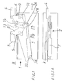
- a mechanism 2 for effecting the actuation of the movable hatch cover sections 3,4 of a ship respectively between the closed position A and the open position B and between the open position B and the closed position A which also comprises pivoting link elements 5,6 movably attached to the respective hatch cover sections 3,4 that are capable of being influenced by force by means of an actuating cylinder hydraulic jack 7, exhibits pivoting link arms 8,9 capable of interacting in pairs.
- Quite small parts of the respective intended hatch cover sections 3,4 are illustrated only schematically in the drawings, because such hatch cover sections normally cover the entire cargo width and longitudinal extent
- the aforementioned link arms 8,9 are supported on a common part 10 of the ship and are each attached at their respective one end 8A,9A to their corresponding hatch cover section 3,4, preferably via so-called claw connections.
- the link arms 8,9 are attached at their respective other end 8B,9B to a divided link connection 11.
- the aforementioned link connection 11 is influenced by force FF,FB by an aforementioned jack 7.
- Both link arms 8,9 are also attached to one another by means of a distance piece 12.
- the link arms 8, 9 are caused to pivot in this way, when force is applied by means of the jack 7, by the forced interaction of the link connection parts 13,14, from the lowered and retracted locked position C to the open position D.
- the respective attached hatch cover section 3,4 is retained in the raised and parted position B.
- the aforementioned divided link connections 11 are formed, as shown in the drawings, by pairs of interacting articulated arms 13,14, which are attached to one another in an articulated fashion at their respective one end 13A,14A via a common articulation 15. At a distance from the aforementioned common articulation 15, each of the two articulated arms 13,14 is attached in an articulated fashion to its corresponding link arm 5,6 via articulations 16,17.
- the aforementioned common articulation 15 is so arranged as to be capable of passing an imaginary straight line 18, which runs between the articulations 16,17 belonging to the respective link arm 8,9, at a given angle X in order to achieve so-called over-centre locking of the two links 8,9 in conjunction with passing the aforementioned imaginary line 18 and in order to permit the release of the locking in conjunction with the return of the aforementioned common articulation 15 past the aforementioned imaginary line 18.
- Both of the respective link arms 8,9 are pivotally mounted via articulations 19,31 and are supported by a common supporting part 10 on the ship.
- An aforementioned supporting part 10 is preferably formed by an elongated beam and/or plate 23, by which the mechanism 2 is supported as a unit 24, which can easily be transported and securely mounted rapidly and simply on the deck of the ship on the frame 21 of the opening alongside its frame top 22 without the need for complicated operations.
- One articulated arm 13 exhibits an angled pivot arm 25, which is directly or indirectly attached to an aforementioned jack 7.
- the aforementioned angled pivot arm 25 is so arranged as to extend at an obtuse angle Z from the remaining part 20 of the associated articulated arm 13, preferably between 100° and 140°.
- the articulation 16 between the aforementioned articulated arm 13 and one of the link arms 8 is situated for this purpose in the area of both pivot arms 20,25 of the aforementioned articulated arm 13, whereby the desired locking and unlocking of the mechanism 2 can be effected simply by respectively retracting and extending the jack 7.
- the two link arms 8,9 are also attached to one another via a rigid arm 12, which functions as a distance piece and is attached in an articulated fashion to fixing lugs 27,28 on the respective link arm 8,9 at its respective one end 8B,9A, as illustrated by way of example in Fig. 4 .
- the link arms 8,9 preferably exhibit triangular form with the articulations 29,30; 16,17 for the hatch cover sections 3,4 and the articulated arm 13 situated at its respective extremities.
- the link attachment parts 13,14 are double, with a pair of links each situated on its own side I, II of the two link arms 8,9.
- the aforementioned mechanism 2 is constructed as a common unit which is so arranged as to be capable of being installed in the position intended for its use simply by being attached to the ship by means of welding and/or bolted joints.
- the aforementioned jack 7 is supported by the aforementioned unit 24 and is pivotally attached at its one end 7A to a pivot 32 that is supported by the aforementioned plate 23 and/or beam 10 and is pivotally attached at its other opposing end 7B to a pivot 26.
Landscapes
- Chemical & Material Sciences (AREA)
- Engineering & Computer Science (AREA)
- Combustion & Propulsion (AREA)
- Mechanical Engineering (AREA)
- Ocean & Marine Engineering (AREA)
- Ship Loading And Unloading (AREA)
- Power-Operated Mechanisms For Wings (AREA)
- Jib Cranes (AREA)
- Load-Engaging Elements For Cranes (AREA)
- Filling Or Discharging Of Gas Storage Vessels (AREA)
- Superstructure Of Vehicle (AREA)
Claims (10)
- Dispositif (1) pour un mécanisme (2) d'actionnement de parties mobiles d'écoutille (3, 4) d'un bateau respectivement entre une position fermée et ouverte (A, B) et entre une position ouverte et fermée (B, A), qui comprend également des éléments pivotants de liaison (5, 6) reliés de manière mobile à la partie d'écoutille respective (3, 4) qui sont susceptibles d'être actionnés de force au moyen d'un vérin hydraulique d'actionnement (7), caractérisé en ce que des paires de bras pivotants de liaison (8, 9), montés sur une partie commune (10) du bateau, sont chacun raccordés au niveau d'une première extrémité respective (8A, 9A), de préférence par l'intermédiaire de connexions à serrage, à la partie d'écoutille correspondante (3, 4), et sont fixés au niveau de leur autre extrémité (8B, 9B) à un raccordement de liaison divisée (11) qui est susceptible d'être actionné de force (FF, FB) par le vérin (7) susmentionné, et en ce que les deux bras de liaison (8, 9) sont fixés l'un à l'autre au moyen d'une pièce d'écartement (12), par laquelle l'application de la force par le vérin provoque, par l'interaction forcée des pièces de raccordement de liaison (13. 14), le pivotement des bras de liaison (8, 9) depuis une position abaissée et verrouillée rétractée (C) vers une position d'ouverture (D), position (D) dans laquelle la partie correspondante de l'écoutille (3, 4) est maintenue dans la position relevée et séparée (B).
- Dispositif selon la revendication 1, caractérisé en ce que les raccordements de liaison divisée (11) sont constitués d'une paire de bras articulés (13, 14) interagissant l'un avec l'autre, qui sont fixés l'un à l'autre de manière articulée au niveau d'une de leur extrémité respective (13A, 14A) par l'intermédiaire d'une articulation commune (15) et sont chacun fixés de manière articulée au bras de liaison correspondant (5, 6) à distance de l'articulation commune (15) susmentionnée,
- Dispositif selon la revendication 2, caractérisé en ce que l'articulation commune (15) susmentionnée est prévue pour pouvoir franchir une ligne droite imaginaire (18), qui court entre les articulations (16, 17) appartenant au bras de liaison respectif (8, 9) afin de réaliser un verrouillage excentré des deux raccordements (8, 9) en même temps que le franchissement de la ligne imaginaire (18) susmentionnée, et afin de permettre le relâchement du verrouillage en même temps que le retour de l'articulation commune (15) susmentionnée au-delà de la ligne imaginaire (18).
- Dispositif selon l'une quelconque des revendications 2 à 3, caractérisé en ce qu'un bras articulé (13) comprend un bras de pivotement coudé (25), raccordé directement ou indirectement au vérin (7) susmentionné.
- Dispositif selon la revendication 4, caractérisé en ce que le bras de pivotement coudé (25) susmentionné se prolonge selon un angle obtus (Z) à partir de la partie restante (20) du bras articulé (13) associé, de préférence compris entre 100° et 140°.
- Dispositif selon l'une quelconque des revendications 4 à 5, caractérisé en ce que le bras articulé (13) susmentionné est fixé au vérin (7) par l'intermédiaire de son bras de pivotement coudé (25).
- Dispositif selon l'une quelconque des revendications précédentes, caractérisé en ce que les deux bras de liaison (8, 9) sont fixés l'un à l'autre par l'intermédiaire d'un bras rigide (12) qui est fixé de manière articulée à des pattes de fixation (27, 28) sur le bras de liaison respectif (8, 9) au niveau de sa première extrémité respective (8B, 9A).
- Dispositif selon l'une quelconque des revendications précédentes, caractérisé en ce que les bras de liaison (8, 9) présentent une forme triangulaire avec les articulations (29, 30 ; 16, 17) pour les parties d'écoutille (3, 4) et le bras articulé (13) situé au niveau de sa zone d'extrémité respective.
- Dispositif selon l'une quelconque des revendications précédentes, caractérisé en ce que les pièces de raccordement de liaison (13, 14) sont doubles comprenant une paire de liens situés chacun de son propre côté (I, II) des deux bras de liaison (8, 9).
- Dispositif selon l'une quelconque des revendications précédentes, caractérisé en ce que le mécanisme (2) susmentionné est construit en tant qu'unité commune (24) pour être installée dans la position d'utilisation prévue en étant simplement fixée au bateau.
Applications Claiming Priority (2)
| Application Number | Priority Date | Filing Date | Title |
|---|---|---|---|
| SE0302466A SE0302466L (sv) | 2003-09-16 | 2003-09-16 | Anordning vid mekanism för fartygs lucksektioner |
| PCT/SE2004/001249 WO2005025977A1 (fr) | 2003-09-16 | 2004-08-31 | Dispositif pour le mecanisme des sections d'ecoutille d'un bateau |
Publications (2)
| Publication Number | Publication Date |
|---|---|
| EP1663772A1 EP1663772A1 (fr) | 2006-06-07 |
| EP1663772B1 true EP1663772B1 (fr) | 2009-06-10 |
Family
ID=29212473
Family Applications (1)
| Application Number | Title | Priority Date | Filing Date |
|---|---|---|---|
| EP04775355A Expired - Lifetime EP1663772B1 (fr) | 2003-09-16 | 2004-08-31 | Dispositif pour le mecanisme des sections d'ecoutille d'un bateau |
Country Status (7)
| Country | Link |
|---|---|
| EP (1) | EP1663772B1 (fr) |
| JP (1) | JP4277043B2 (fr) |
| KR (1) | KR101122320B1 (fr) |
| CN (1) | CN100586790C (fr) |
| NO (1) | NO335481B1 (fr) |
| SE (1) | SE0302466L (fr) |
| WO (1) | WO2005025977A1 (fr) |
Families Citing this family (8)
| Publication number | Priority date | Publication date | Assignee | Title |
|---|---|---|---|---|
| SE532596C2 (sv) * | 2006-05-30 | 2010-03-02 | Tts Ships Equipment Ab | Anordning vid mekanism för manövrering av fartygs förskjutbart rörliga lucksektioner |
| KR101138170B1 (ko) * | 2009-09-03 | 2012-04-25 | 현대중공업 주식회사 | 해치 커버용 링크식 승하강 구동장치 |
| CN102050200B (zh) * | 2009-10-29 | 2013-04-10 | 范茂荣 | 侧开双片防浪门 |
| RU2571531C1 (ru) | 2012-04-04 | 2015-12-20 | Бикон Финлэнд Лтд Ой | Устройство, узел и способ фиксации подводного люка или другой съемной конструкции |
| CN103061635B (zh) * | 2013-01-18 | 2015-03-25 | 上海科得威船舶技术工程有限公司 | 一种舱盖开启装置 |
| CN107842534A (zh) * | 2017-09-29 | 2018-03-27 | 江苏威和海洋工程设备有限公司 | 一种舱口盖液压油缸组 |
| CN111661244B (zh) * | 2020-05-13 | 2021-07-23 | 上海海事大学 | 一种船舶安全舱盖 |
| KR102729257B1 (ko) * | 2023-12-26 | 2024-11-13 | 유한회사 케이조선앤특수선 | 멀티 링크 구조의 선박용 매립형 해치커버 |
Family Cites Families (8)
| Publication number | Priority date | Publication date | Assignee | Title |
|---|---|---|---|---|
| US3272255A (en) * | 1954-04-12 | 1966-09-13 | Macgregor & Company Naval Arch | Power operating means for opening and closing hatch covers |
| US3330329A (en) * | 1965-09-13 | 1967-07-11 | David R Ligh | Hatch cover operating arrangement |
| US3335783A (en) * | 1965-10-22 | 1967-08-15 | David R Ligh | Actuator for folding closure |
| FR2529162B1 (fr) * | 1982-06-25 | 1986-12-26 | Kone Oy | Dispositif pour le verrouillage automatique d'un panneau d'ecoutille en position de fermeture ou d'ouverture |
| SE468940B (sv) * | 1989-03-17 | 1993-04-19 | Kvaerner Ships Equipment | Anordning vid ledarrangemang foer en lucka eller annat liknande tillslutningsorgan |
| FI110178B (fi) * | 1998-03-09 | 2002-12-13 | Macgregor Fin Oy | Rahtilaivan lastitilan aukon peittävän lastiluukun kääntölaite |
| JP4721506B2 (ja) * | 2000-11-24 | 2011-07-13 | カヤバ システム マシナリー株式会社 | 船舶のハッチ開閉構造 |
| FI109985B (fi) * | 2001-05-07 | 2002-11-15 | Macgregor Fin Oy | Rahtilaivan lastiluukun nostolaitteen lukitusmekanismi |
-
2003
- 2003-09-16 SE SE0302466A patent/SE0302466L/xx not_active IP Right Cessation
- 2003-11-04 CN CN200310104763A patent/CN100586790C/zh not_active Expired - Fee Related
-
2004
- 2004-08-31 JP JP2006526850A patent/JP4277043B2/ja not_active Expired - Fee Related
- 2004-08-31 EP EP04775355A patent/EP1663772B1/fr not_active Expired - Lifetime
- 2004-08-31 KR KR1020067005289A patent/KR101122320B1/ko not_active Expired - Fee Related
- 2004-08-31 WO PCT/SE2004/001249 patent/WO2005025977A1/fr not_active Ceased
-
2006
- 2006-01-25 NO NO20060393A patent/NO335481B1/no not_active IP Right Cessation
Also Published As
| Publication number | Publication date |
|---|---|
| KR101122320B1 (ko) | 2012-03-26 |
| NO20060393L (no) | 2006-06-07 |
| SE524479C2 (sv) | 2004-08-17 |
| CN1597441A (zh) | 2005-03-23 |
| SE0302466L (sv) | 2004-08-17 |
| KR20060076774A (ko) | 2006-07-04 |
| CN100586790C (zh) | 2010-02-03 |
| NO335481B1 (no) | 2014-12-15 |
| EP1663772A1 (fr) | 2006-06-07 |
| JP4277043B2 (ja) | 2009-06-10 |
| SE0302466D0 (sv) | 2003-09-16 |
| JP2007505785A (ja) | 2007-03-15 |
| WO2005025977A1 (fr) | 2005-03-24 |
Similar Documents
| Publication | Publication Date | Title |
|---|---|---|
| US5261779A (en) | Dual hydraulic, parallelogram arm wheelchair lift | |
| US6048021A (en) | Convertible top mechanism with powered rear row | |
| EP2352671B1 (fr) | Porte de travée du train d'atterrissage avec mécanisme à crochet double | |
| US4806062A (en) | Stowable lift for freight vehicles | |
| WO2011154527A1 (fr) | Dispositif de pivotement d'un ou de plusieurs rabats frontaux d'un véhicule se déplaçant sur une voie, et module de rabats frontaux | |
| EP3737633B1 (fr) | Structure de levage hydraulique à mouvement de levage vertical pour véhicules à moteur et véhicules similaires | |
| CA2045361A1 (fr) | Boite de caisse de camion | |
| CA1093260A (fr) | Dispositif servant a escamoter et a deployer une rampe d'acces mobile | |
| EP1663772A1 (fr) | Dispositif pour le mecanisme des sections d'ecoutille d'un bateau | |
| CA3009921A1 (fr) | Dispositif rail-route vertical | |
| HU222207B1 (hu) | Oldalfal egy jármű felépítményéhez | |
| US6273000B1 (en) | Rail switching system | |
| CN101092162B (zh) | 货轮舱盖的驱动器机构 | |
| EP0837814B1 (fr) | Dispositif pour un navire | |
| US5301626A (en) | Cargo hatch cover mechanism | |
| WO2001068442A1 (fr) | Dispositif destine a une rampe de chargement de bateaux | |
| JP4049573B2 (ja) | 壁面開閉装置付き車両荷台カバー構体 | |
| US6715235B2 (en) | Seal for a pivoting ship door | |
| WO1997008047A1 (fr) | Systeme de porte coulissante de bateau | |
| EP1062150A1 (fr) | Mecanisme rotatif pour panneaux de cale de navires de charge | |
| WO2000075011A1 (fr) | Guidage de porte | |
| EP2197779B1 (fr) | Bras mécanique articulé | |
| CN206202299U (zh) | 用于一个或多个车头活门的锁止装置 | |
| AT400945B (de) | Ladebrücke für ein lastfahrzeug | |
| SU998221A1 (ru) | Судовое люковое закрытие |
Legal Events
| Date | Code | Title | Description |
|---|---|---|---|
| PUAI | Public reference made under article 153(3) epc to a published international application that has entered the european phase |
Free format text: ORIGINAL CODE: 0009012 |
|
| 17P | Request for examination filed |
Effective date: 20060303 |
|
| AK | Designated contracting states |
Kind code of ref document: A1 Designated state(s): GB GR IT |
|
| DAX | Request for extension of the european patent (deleted) | ||
| RBV | Designated contracting states (corrected) |
Designated state(s): GB GR IT |
|
| RIN1 | Information on inventor provided before grant (corrected) |
Inventor name: WEITER, ANNA |
|
| GRAP | Despatch of communication of intention to grant a patent |
Free format text: ORIGINAL CODE: EPIDOSNIGR1 |
|
| GRAS | Grant fee paid |
Free format text: ORIGINAL CODE: EPIDOSNIGR3 |
|
| GRAA | (expected) grant |
Free format text: ORIGINAL CODE: 0009210 |
|
| AK | Designated contracting states |
Kind code of ref document: B1 Designated state(s): GB GR IT |
|
| REG | Reference to a national code |
Ref country code: GB Ref legal event code: FG4D |
|
| REG | Reference to a national code |
Ref country code: GR Ref legal event code: EP Ref document number: 20090401901 Country of ref document: GR |
|
| PLBE | No opposition filed within time limit |
Free format text: ORIGINAL CODE: 0009261 |
|
| STAA | Information on the status of an ep patent application or granted ep patent |
Free format text: STATUS: NO OPPOSITION FILED WITHIN TIME LIMIT |
|
| 26N | No opposition filed |
Effective date: 20100311 |
|
| GBPC | Gb: european patent ceased through non-payment of renewal fee |
Effective date: 20090910 |
|
| PG25 | Lapsed in a contracting state [announced via postgrant information from national office to epo] |
Ref country code: GB Free format text: LAPSE BECAUSE OF NON-PAYMENT OF DUE FEES Effective date: 20090910 |
|
| PG25 | Lapsed in a contracting state [announced via postgrant information from national office to epo] |
Ref country code: IT Free format text: LAPSE BECAUSE OF FAILURE TO SUBMIT A TRANSLATION OF THE DESCRIPTION OR TO PAY THE FEE WITHIN THE PRESCRIBED TIME-LIMIT Effective date: 20090610 |
|
| PGFP | Annual fee paid to national office [announced via postgrant information from national office to epo] |
Ref country code: GR Payment date: 20140828 Year of fee payment: 11 |
|
| PG25 | Lapsed in a contracting state [announced via postgrant information from national office to epo] |
Ref country code: GR Free format text: LAPSE BECAUSE OF NON-PAYMENT OF DUE FEES Effective date: 20160303 |
|
| REG | Reference to a national code |
Ref country code: GR Ref legal event code: ML Ref document number: 20090401901 Country of ref document: GR Effective date: 20160303 |