EP1664478B1 - Systeme de forage et procede associe - Google Patents
Systeme de forage et procede associe Download PDFInfo
- Publication number
- EP1664478B1 EP1664478B1 EP04766324A EP04766324A EP1664478B1 EP 1664478 B1 EP1664478 B1 EP 1664478B1 EP 04766324 A EP04766324 A EP 04766324A EP 04766324 A EP04766324 A EP 04766324A EP 1664478 B1 EP1664478 B1 EP 1664478B1
- Authority
- EP
- European Patent Office
- Prior art keywords
- pressure
- fluid
- injection
- drilling
- drilling fluid
- Prior art date
- Legal status (The legal status is an assumption and is not a legal conclusion. Google has not performed a legal analysis and makes no representation as to the accuracy of the status listed.)
- Expired - Lifetime
Links
- 238000005553 drilling Methods 0.000 title claims abstract description 163
- 238000000034 method Methods 0.000 title claims description 11
- 239000012530 fluid Substances 0.000 claims abstract description 283
- 238000002347 injection Methods 0.000 claims abstract description 160
- 239000007924 injection Substances 0.000 claims abstract description 160
- 230000015572 biosynthetic process Effects 0.000 claims abstract description 22
- 238000004891 communication Methods 0.000 claims abstract description 11
- 238000005086 pumping Methods 0.000 claims abstract description 7
- 230000001276 controlling effect Effects 0.000 claims description 23
- 238000012544 monitoring process Methods 0.000 claims description 13
- 230000001105 regulatory effect Effects 0.000 claims description 4
- 241000711981 Sais Species 0.000 abstract 1
- 238000005755 formation reaction Methods 0.000 description 19
- 239000007789 gas Substances 0.000 description 13
- 238000005520 cutting process Methods 0.000 description 8
- 239000000203 mixture Substances 0.000 description 7
- 230000006870 function Effects 0.000 description 6
- 230000002706 hydrostatic effect Effects 0.000 description 6
- 238000005259 measurement Methods 0.000 description 6
- 230000033001 locomotion Effects 0.000 description 5
- 239000007787 solid Substances 0.000 description 5
- 230000003068 static effect Effects 0.000 description 4
- 238000011144 upstream manufacturing Methods 0.000 description 4
- 238000010586 diagram Methods 0.000 description 3
- 230000035515 penetration Effects 0.000 description 3
- 239000011148 porous material Substances 0.000 description 3
- 238000000926 separation method Methods 0.000 description 3
- IJGRMHOSHXDMSA-UHFFFAOYSA-N Atomic nitrogen Chemical compound N#N IJGRMHOSHXDMSA-UHFFFAOYSA-N 0.000 description 2
- 239000000654 additive Substances 0.000 description 2
- 238000009530 blood pressure measurement Methods 0.000 description 2
- 238000012937 correction Methods 0.000 description 2
- 229910001873 dinitrogen Inorganic materials 0.000 description 2
- 229930195733 hydrocarbon Natural products 0.000 description 2
- 150000002430 hydrocarbons Chemical class 0.000 description 2
- 239000007788 liquid Substances 0.000 description 2
- 230000004044 response Effects 0.000 description 2
- 238000009825 accumulation Methods 0.000 description 1
- 230000008901 benefit Effects 0.000 description 1
- 230000005540 biological transmission Effects 0.000 description 1
- 230000008859 change Effects 0.000 description 1
- 230000006835 compression Effects 0.000 description 1
- 238000007906 compression Methods 0.000 description 1
- 238000001816 cooling Methods 0.000 description 1
- 238000006073 displacement reaction Methods 0.000 description 1
- 230000000694 effects Effects 0.000 description 1
- 230000006872 improvement Effects 0.000 description 1
- 239000011261 inert gas Substances 0.000 description 1
- 230000003993 interaction Effects 0.000 description 1
- 238000004519 manufacturing process Methods 0.000 description 1
- 230000008569 process Effects 0.000 description 1
- 238000003860 storage Methods 0.000 description 1
- 239000000126 substance Substances 0.000 description 1
- 230000001360 synchronised effect Effects 0.000 description 1
- 238000012546 transfer Methods 0.000 description 1
- XLYOFNOQVPJJNP-UHFFFAOYSA-N water Substances O XLYOFNOQVPJJNP-UHFFFAOYSA-N 0.000 description 1
Images


Classifications
-
- E—FIXED CONSTRUCTIONS
- E21—EARTH OR ROCK DRILLING; MINING
- E21B—EARTH OR ROCK DRILLING; OBTAINING OIL, GAS, WATER, SOLUBLE OR MELTABLE MATERIALS OR A SLURRY OF MINERALS FROM WELLS
- E21B21/00—Methods or apparatus for flushing boreholes, e.g. by use of exhaust air from motor
- E21B21/08—Controlling or monitoring pressure or flow of drilling fluid, e.g. automatic filling of boreholes, automatic control of bottom pressure
-
- E—FIXED CONSTRUCTIONS
- E21—EARTH OR ROCK DRILLING; MINING
- E21B—EARTH OR ROCK DRILLING; OBTAINING OIL, GAS, WATER, SOLUBLE OR MELTABLE MATERIALS OR A SLURRY OF MINERALS FROM WELLS
- E21B47/00—Survey of boreholes or wells
- E21B47/12—Means for transmitting measuring-signals or control signals from the well to the surface, or from the surface to the well, e.g. for logging while drilling
Definitions
- the present invention relates to a drilling system and method for drilling a bore hole into an earth formation.
- a drilling rig that is used to support and rotate a drill string, comprised of a series of drill tubulars with a drill bit mounted at the end.
- a pumping system is used to circulate a fluid, comprised of a base fluid, typically water or oil, and various additives down the drill string, the fluid then exits through the rotating drill bit and flows back to surface via the annular space formed between the borehole wall and the drill string.
- the drilling fluid serves the following purposes: (a) provide support to the borehole wall, (b) prevent or, in case of under balanced drilling (UBD), control formation fluids or gasses from entering the well, (c) transport the cuttings produced by the drill bit to surface, (d) provide hydraulic power to tools fixed in the drill string and (e) cooling of the bit.
- ULD under balanced drilling
- the drilling fluid flows back into a mud handling system, generally comprised of a shaker table, to remove solids, a mud pit and a manual or automatic means for addition of various chemicals or additives to keep the properties of the returned fluid as required for the drilling operation.
- a mud handling system generally comprised of a shaker table, to remove solids, a mud pit and a manual or automatic means for addition of various chemicals or additives to keep the properties of the returned fluid as required for the drilling operation.
- the drilling fluid exerts a pressure against the well bore inside wall that is mainly built-up of a hydrostatic part, related to the weight of the mud column, and a dynamic part related frictional pressure losses caused by, for instance, the fluid circulation rate or movement of the drill string.
- the fluid pressure in the well is selected such that, while the fluid is static or circulated during drilling operations, it does not exceed the formation fracture pressure or formation strength. If the formation strength is exceeded, formation fractures will occur which will create drilling problems such as fluid losses and borehole instability.
- the fluid density is chosen such that the pressure in the well is always maintained above the pore pressure to avoid formation fluids entering the well, while during UBD the pressure in the well is maintained just below the power pressure to controllably allow formation fluids entering the well (primary well control).
- the pressure margin with on one side the pore pressure and on the other side the formation strength is known as the "Operational Window”.
- BOP BlowOut Preventer
- a BlowOut Preventer can be mounted on the well head, below the rig floor, which BOP can shut off the wellbore in case formation fluids or gas should enter the wellbore (secondary well control) in an unwanted or uncontrolled way.
- Such unwanted inflows are commonly referred to as "kicks".
- the BOP will normally only be used in emergency i.e. well-control situations.
- a drilling system for drilling a bore hole into an earth formation the bore hole having an inside wall, and the system comprising:
- the invention also provides a drilling method for drilling a bore hole into an earth formation, the bore hole having an inside wall, the drilling method comprising the steps of:
- the injection fluid pressure in the injection fluid supply passage represents a relatively accurate indicator for the drilling fluid pressure in the drilling fluid gap at the depth where the injection fluid is injected into the drilling fluid gap. Therefore, a pressure signal generated by an injection fluid pressure sensor anywhere in the injection fluid supply passage can be suitably utilized, for instance as an input signal for controlling the back pressure means, for monitoring the drilling fluid pressure in the drilling fluid return passage.
- the pressure signal can, if so desired, optionally be compensated for the weight of the injection fluid column and/or for the dynamic pressure loss that may be generated in the injection fluid between the injection fluid pressure sensor in the injection fluid supply passage and where the injection into the drilling fluid return passage takes place, for instance, in order to obtain an exact value of the injection pressure in the drilling fluid return passage at the depth where the injection fluid is injected into the drilling fluid gap.
- the injection fluid supply passage can preferably be dedicated to one task, which is supplying the injection fluid for injection into the drilling fluid gap. This way, its hydrostatic and hydrodynamic interaction with the injection fluid can be accurately determined and kept constant during an operation, so that the weight of the injection fluid and dynamic pressure loss in the supply passage can be accurately established.
- the invention is at least applicable to pressure control during under-balanced drilling operations, at balance drilling operations, over-balance drilling operations or completion operations.
- the invention is enabled with only one injection fluid pressure sensor, but that a plurality of injection fluid pressure sensors can be utilized, if so desired, for instance positioned in mutually different locations.
- WO 02/084067 describes a drilling well configuration wherein the drilling fluid gap is formed by an inner well bore annulus, and an injection fluid supply passage is provided in the form of a second, outer annulus, for bringing the injection fluid from the surface level to a desired injection depth. Fluid is injected into the inner annulus for dynamically controlling bottom hole circulation pressure in the well bore wherein a high injection rate of a light fluid results in a low bottom hole pressure.
- the present patent application utilizes back pressure means for controlling the bottom hole pressure, whereby the injection fluid injection pressure is utilized for controlling the back pressure means.
- the preamble of the independent claims corresponds to US-A-3470971. It has been found that, by controlling back pressure means in response of the injection fluid injection pressure, the down hole pressure is more accurately controllable and more stable than by controlling the down hole pressure by directly regulating the injection fluid injection rate.
- the injection fluid injection rate may be controlled in concert with controlling the back pressure means. This is of particular advantage when starting or stopping circulation in order to avoid the injection fluid injection rate being maintained at unrealistic values.
- the pressure difference of the drilling fluid in the drilling fluid return passage in a lower part of the bore hole stretching between the injection fluid injection point and the bottom of the well bore can be calculated using a hydraulic model taking into account inter alia the well geometry. Since the hydraulic model is herewith only used for calculating the pressure differential over a relatively small section of the bore hole, the precision is expected to be much better than when the pressure differential over the entire well length must be calculated.
- the injection fluid is preferably injected as close as possible to the bottom of the bore hole.
- the injection fluid supply passage is preferably led to or close to the surface level from where the drill string reaches into the bore hole, thereby providing an opportunity to generate the pressure signal at surface or close to the surface. This is more convenient, and in particular allows for faster monitoring of the pressure signal, than when the pressure signal would be generated at great depth below the surface level.
- the injection fluid can be a liquid or a gas.
- the injection fluid injection system is arranged to inject an injection fluid having a mass density lower than that of the drilling fluid.
- the hydrostatic component to the down hole pressure is reduced. This allows for a higher dynamic range of control for the back pressure means.
- the injection fluid is preferably provided in the form of a gas, particularly an inert gas such as for example nitrogen gas (N2).
- a gas particularly an inert gas such as for example nitrogen gas (N2).
- N2 nitrogen gas
- the dynamic pressure loss of the gas in the injection fluid supply passage can optionally be taken into account, but its contribution to the pressure signal is expected to be low compared to the weight of the gas column.
- the gas pressure compensated for the weight of the gas column may for practical purposes be assumed to be almost equal to the drilling fluid pressure in the drilling fluid gap at the injection depth.
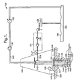
- FIG. 1 is a schematic view of a drilling apparatus according to an embodiment of the invention
- Fig. 1 is a schematic view depicting a surface drilling system 100 employing the current invention. It will be appreciated that an offshore drilling system may likewise employ the current invention.
- the drilling system 100 is shown as being comprised of a drilling rig 102 that is used to support drilling operations. Many of the components used on a rig 102, such as the kelly, power tongs, slips, draw works and other equipment are not shown for ease of depiction.
- the rig 102 is used to support drilling and exploration operations in a formation 104.
- a borehole 106 has already been partially drilled.
- a drill string 112 reaches into the bore bole 106, thereby forming a well bore annulus between the bore hole wall and the drill string 112, and/or between an optional casing 101 and the drill string 112.
- One of the functions of the drill string 112 is to convey a drilling fluid 150, the use of which is required in a drilling operation, to the bottom of the bore hole and into the well bore annulus.
- the drill string 112 supports a bottom hole assembly (BHA) 113 that includes a drill bit 120, a mud motor 118, a sensor package 119, a check valve (not shown) to prevent backflow of drilling fluid from the well bore annulus into the drill string.
- BHA bottom hole assembly
- the sensor package 119 may for instance be provided in the form of a MWD/LWD sensor suite. In particular it may include a pressure transducer 116 to determine the annular pressure of drilling fluid in or near the bottom of the hole.
- the BHA 113 in the shown embodiment also includes a telemetry package 122 that can be used to transmit pressure information, MWD/LWD information as well as drilling information to be received at the surface.
- a data memory including a pressure data memory may be provided for temporary storage of collected pressure data before transmittal of the information.
- the drilling fluid 150 may be stored in a reservoir 136, which in Fig. 1 is depicted in the form of a mud pit.
- the reservoir 136 is in fluid communications with pump means, particularly primary pump means, comprising one or more mud pumps 138 that, in operation, pump the drilling fluid 150 through a conduit 140.
- An optional flow meter 152 can be provided in series with one or more mud pumps, either upstream or downstream thereof.
- the conduit 140 is connected to the last joint of the drill string 112.
- the drilling fluid 150 is pumped down through the drill string 112 and the BHA 113 and exits the drill bit 120, where it circulates the cuttings away from the bit 120 and returns them up a drilling fluid return passage 115 which is typically formed by the well bore annulus-
- the drilling fluid 150 returns to the surface and goes through a side outlet, through drilling fluid discharge conduit 124 and optionally through various surge tanks and telemetry systems (not shown).
- An injection fluid supply passage is provided in the form of an outer annulus 141.
- the outer annulus 141 fluidly connects an injection fluid supply 143 with the drilling fluid return passage 115, in which gap an injection fluid can be injected through injection point 144.
- the injection fluid supply 143 is located on the surface.
- a variable flow-restricting device such as an injection choke or an injection valve, is optionally provided to separate the injection fluid supply passage 141 from the drilling fluid return passage 115.
- injection of the injection fluid into the drilling fluid can be interrupted while maintaining pressurisation of the injection fluid supply passage.
- the injection fluid has a lower density than the drilling fluid, such that the hydrostatic pressure in the bottom hole area, in the vicinity of the drill bit 120, is reduced due to a lower weight of the body of fluid present in the fluid return passage 115.
- the injection fluid is injected in the form of a gas, which can be, for example, nitrogen gas.
- An injection fluid pressure sensor 156 is provided, in fluid communication with the injection fluid supply passage, for monitoring a pressure of the injection fluid in the injection fluid supply passage 144.
- the injection fluid supply passage 141 is led to the surface level on the rig, so that the injection fluid pressure sensor 156 can be located at the surface level and the pressure data generated by the injection fluid pressure sensor 156 is readily available at surface.
- a mixture of drilling fluid 150, possibly including cuttings, and the injection fluid flows through an upper part 149 of the annulus 115, down stream of the injection point 144. Thereafter the mixture proceeds to what is generally referred to as the backpressure system 131.
- a pressure isolating seal is provided to seal against the drill string and contain a pressure in the well bore annulus.
- the pressure isolating seal is provided in the form of a rotating control head on top of the BOP 142, through which rotating control head the drill string passes.
- the rotating control head on top of the BOP forms, when activated, a seal around the drill string 112, isolating the pressure, but still permitting drill string rotation and reciprocation.
- a rotating BOP may be utilized.
- the pressure isolating seal can be regarded to be a part of the back pressure system.
- back pressure means arranged to provide an adjustable back pressure on the drilling fluid mixture contained in the well bore annulus 115.
- the back pressure means comprises a variable flow restrictive device, suitably in the form of a wear resistant choke 130. It will be appreciated that there exist chokes designed to operate in an environment where the drilling fluid 150 contains substantial drill cuttings and other solids. Choke 130 is one such type and is further capable of operating at variable pressures, flowrates and through multiple duty cycles.
- the drilling fluid 150 exits the choke 130 and flows through an optional flow meter 126 to be directed through an optional degasser 1 and solids separation equipment 129.
- Optional degasser 1 and solids separation equipment 129 are designed to remove excess gas and other contaminates, including cuttings, from the drilling fluid 150. After passing solids separation equipment 129, the drilling fluid 150 is returned to reservoir 136.
- Flow meter 126 may be a mass-balance type or other high-resolution flow meter.
- a back pressure sensor 147 can be optionally provided in the drilling fluid discharge conduit 124 upstream of the variable flow restrictive device.
- a flow meter, similar to flow meter 126, may be placed upstream of the back pressure means 131 in addition to the back pressure sensor 147.
- Back pressure control means including a pressure monitoring system 146 are provided for monitoring data relevant for the annulus pressure, and providing control signals to at least the back pressure system 131 and optionally also to the injection fluid injection system and/or to the primary pump means.
- the required back pressure to obtain the desired down hole pressure is determined by obtaining information on the existing down hole pressure of the drilling fluid in the vicinity of the BHA 113, referred to as the bottom hole pressure, comparing the information with a desired down hole pressure and utilizing the differential between these for determining a set-point back pressure and controlling the back pressure means in order to establish a back pressure close to the set-point back pressure.
- the pressure of the injection fluid in the injection fluid supply passage 141 is advantageously utilized for obtaining information relevant for determining the current bottom hole pressure. As long as the injection fluid is being injected into the drilling fluid return stream, the pressure of the injection fluid at the injection depth can be assumed to be equal to the drilling fluid pressure at the injection point 144. Thus, the pressure as determined by injection fluid pressure sensor 156 can advantageously be utilized to generate a pressure signal for use as a feedback signal for controlling or regulating the back pressure system.
- One possible way to utilize the pressure signal corresponding to the injection fluid pressure is to control the back pressure system so as to maintain the injection fluid pressure on a certain suitable constant value throughout the drilling or completion operation.
- the accuracy is increased when the injection point 144 is in close proximity to the bottom of the bore hole.
- the magnitude of the pressure differential over the part of the drilling fluid return passage stretching between the injection point 144 and the bottom of the hole is preferably to be established.
- a hydraulic model can be utilized as will be described below.
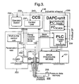
- FIG. 3 is a block diagram of a possible pressure monitoring system 146.
- System inputs to this monitoring system 146 include the injection fluid pressure 203 that has been measured by the injection fluid pressure sensor 156, and can include the down hole pressure 202 that has been measured by sensor package 119, transmitted by MWD pulser package 122 (or other telemetry system) and received by transducer equipment (not shown) on the surface.
- Other system inputs include pump pressure 200, input flow rate 204 from flow meter 152 or from mud pump strokes compensated for efficiency, penetration rate and string rotation rate, as well as weight on bit (WOB) and torque on bit (TOB) that may be transmitted from the BHA 113 up the annulus as a pressure pulse.
- Return flow is optionally measured using flow meter 126, if provided.
- Signals representative of the data inputs are transmitted to a control unit (CCS) 230, which is in it self comprised of a drill rig control unit 232, one or more drilling operator's stations 234, a dynamic annular pressure control (DAPC) processor 236 and a back pressure programmable logic controller (PLC) 238, all of which are connected by a common data network or industrial type bus 240.
- the CCS 230 is arranged to receive and collect data and make the data accessible via the common data network or industrial type bus 240 to the DAPC processor 236.
- the DAPC processor 236 can suitably be a personal computer based SCADA system running a hydraulic model and connected to the PLC 238.
- the DAPC processor 236 serves three functions, monitoring the state of the borehole pressure during drilling operations, predicting borehole response to continued drilling, and issuing commands to the backpressure PLC to control the back pressure means 131. In addition, commands may also be issued to one or more of the primary pump means 138 and the injection fluid injection system.
- the specific logic associated with the DAPC processor 236 will be discussed further below.
- a schematic model of the functionality of the DAPC pressure monitoring system 146 is set forth in Figure 4.
- the DAPC processor 236 includes programming to carry out control functions and Real Time Model Calibration functions.
- the DAPC processor receives input data from various sources and continuously calculates in real time the correct backpressure set-point to achieve the desired down hole pressure.
- the set-point is then transferred to the programmable logic controller 238, which generates the control signals for controlling the back pressure means 131.
- the pressure 263 in the annulus at the injection fluid injection depth is determined by means of a control module 259, thereby utilizing some fixed well parameters 250 including depth of the injection point 144, and some fixed injection fluid data 255 such as specific mass of the injection fluid, and some variable injection fluid injection data 257 including at least pressure signal 203 generated by injection fluid pressure sensor 156 and optionally data such as the injection fluid injection rate.
- the injection fluid supply passage 141 is led to the surface level on the rig, so that data generated by the injection fluid pressure sensor 156 is readily available as input signal for the back pressure control system.
- the pressure in the annulus 115 at the injection depth can be assumed to be equal to the injection fluid pressure at surface compensated for the weight of the injection fluid column.
- a dynamic pressure loss must be taken into account as well.
- the pressure differential 262 over a lower part of the annulus, the lower part stretching between the injection point 144 and the bottom hole vicinity, is added to the pressure 263 at the injection point 144.
- the input parameters for determining this pressure differential fall into three main groups.
- the first are relatively fixed parameters 250, including parameters such as well, drill string, hole and casing geometry, drill bit nozzle diameters, and well trajectory. While it is recognized that the actual well trajectory may vary from the planned trajectory, the variance may be taken into account with a correction to the planned trajectory.
- temperature profile of the fluid in the annulus and the fluid composition As with the geometrical parameters, these are generally known and do not vary quickly over the course of the drilling operations.
- one objective is keeping the drilling fluid 150 density and composition relatively constant, using backpressure to provide the additional pressure for control of the annulus pressure.
- the second group of parameters 252 are highly variable in nature and are sensed and logged in real time.
- the rig data acquisition system provides this information via common data network 240 to the DAPC processor 236.
- This information includes injection fluid pressure data 203 generated by injection fluid pressure sensor 156, flow rate data provided by both down hole and return flow meters 152 and 126 and/or by measurement of pump strokes, respectively, the drill string rate of penetration (ROP) or velocity, the drill string rotational velocity, the bit depth, and the well depth, all the latter being derived from direct rig sensor measurements.
- ROP drill string rate of penetration
- down hole pressure data 254 is provided by a pressure-sensing tool 116, optionally via pressure data memory 205, located in the bottom hole assembly 113. Data gathered with this tool is transmitted to surface by the down hole telemetry package 122. It is appreciated that most of current telemetry systems have limited data transmission capacity and/or velocity. The measured pressure data could therefore be received at surface with some delay. Other system input parameters are the desired set-point for the down hole pressure 256 and the depth at which the set-point should be maintained. This information is usually provided by the operator.
- a control module 258 calculates the pressure in the annulus over the lower part well bore length stretching between the injection point 144 and the bottom hole utilizing various models.
- the pressure differential in the well bore is a function not only of the static pressure or weight of the relevant fluid column in the well, but also includes pressures losses caused by drilling operations, including fluid displacement by the drill string, frictional pressure losses caused by fluid motion in the annulus, and other factors.
- the control module 258 considers the relevant part of the well as a finite number of elements, each assigned to a relevant segment of well bore length. In each of the elements the dynamic pressure and the fluid weight is calculated and used to determine the pressure differential 262 for the segment. The segments are summed and the pressure differential for at least the lower end of the well profile is determined.
- the velocity of the fluid in the well bore is proportional to the flow rate of the fluid 150 being pumped down hole plus the fluid flow produced from the formation 104 below the injection point 144, the latter contribution being relevant for under-balanced conditions.
- a measurement of the pumped flow and an estimate of the fluid produced from the formation 104 are used to calculate the total flow through the bore hole and the corresponding dynamic pressure loss.
- the calculation is made for a series of segments of the well, taking into account the fluid compressibility, estimated cutting loading and the thermal expansion of the fluid for the specified segment, which is itself related to the temperature profile for that segment of the well.
- the fluid viscosity at the temperature profile for the segment is also instrumental in determining dynamic pressure losses for the segment.
- the composition of the fluid is also considered in determining compressibility and the thermal expansion coefficient.
- the drill string movement in particular its rate of penetration (ROP), is related to the surge and swab pressures encountered during drilling operations as the drill string is moved into or out of the borehole.
- the drill string rotation is also used to determine dynamic pressure losses, as it creates a frictional force between the fluid in the annulus and the drill string.
- the bit depth, well depth, and well/string geometry are all used to help create the borehole segments to be modelled.
- the preferred embodiment considers not only the hydrostatic pressure exerted by fluid 150, but also the fluid compression, fluid thermal expansion and the cuttings loading of the fluid seen during operations. All of these factors go into a calculation of the "static pressure".
- Dynamic pressure considers many of the same factors in determining static pressure. However, it further considers a number of other factors. Among them is the concept of laminar versus turbulent flow. The flow characteristics are a function of the estimated roughness, hole and string geometry and the flow velocity, density and viscosity of the fluid. The above includes borehole eccentricity and specific drill pipe geometry (box/pin upsets) that affect the flow velocity seen in the borehole annulus. The dynamic pressure calculation further includes cuttings accumulation down hole, string movement's (axial movement and rotation) effect on dynamic pressure of the fluid.
- the pressure differential for the entire annulus is determined in accordance with the above, and compared to the set-point pressure 256 in the control module 264.
- the desired backpressure 266 is then determined and passed on to a programmable logic controller 238, which generates back pressure control signals.
- down hole pressure and estimates of fluid viscosity and fluid density.
- These parameters can be determined down hole, for instance using sensor package 119, and transmitted up the mud column using pressure pulses that travel to surface at approximately the speed of sound, for instance by means of telemetry system 122.
- This travelling speed and the limited bandwidth of such systems usually cause a delay between measuring the data down hole and receiving the data at surface. This delay can range from a few seconds up to several minutes. Consequently, down hole pressure measurements can often not be input to the DAPC model on a real time basis. Accordingly, it will be appreciated that there is likely to be a difference between the measured down hole pressure, when transmitted up to the surface, and the predicted down hole pressure for that depth at the time the data is received at surface.
- the down hole pressure data is preferably time stamped or depth stamped to allow the control system to synchronize the received pressure data with historical pressure predictions stored in memory.
- the DAPC system uses a regression method to compute adjustments to some input parameters to obtain the best correlation between predictions and measurements of down hole pressure.
- the corrections to input parameters may be made by varying any of the available variable input parameters.
- only the fluid density and the fluid viscosity are modified in order to correct the predicted down hole pressure.
- the actual down hole pressure measurement is used only to calibrate the calculated down hole pressure. It is not utilized to directly adjust the backpressure set-point.
- FIG. 5 shows an alternative embodiment of a drilling system employing the invention.
- the system of Fig. 5 includes a back pressure system 131 that is provided with pressurizing means, here shown in the form of back pressure pump 128, in parallel fluid communication with the drilling fluid return passage 115 and the choke 130, to pressurize the drilling fluid in the drilling fluid discharge conduit 124 upstream of the flow restrictive device 130.
- the low-pressure end of the back pressure pump 128 is connected, via conduit 119, to a drilling fluid supply which may be in communication with reservoir 136.
- Stop valve 125' may be provided in conduit 119 to isolate the back pressure pump 128 from the drilling fluid supply.
- valve 123 may be provided to.selectively isolate the back pressure pump 128 from the drilling fluid discharge system.
- Back pressure pump 128 can be engaged to ensure that sufficient flow passes the choke system 130 to be able to maintain backpressure, even when there is insufficient flow coming from the annulus 115 to maintain pressure on choke 130.
- the back pressure control means in this embodiment can generate the control signals for the back pressure system, suitably adjusting not only the variable choke 130 but also the back pressure pump 128 and/or valve 123.
- FIG. 6 shows still another embodiment of the drilling system, wherein in addition to the features of Fig. 5, the drilling fluid reservoir comprises a trip tank 2 in addition to the mud pit.
- a trip tank is normally used on a rig to monitor fluid gains and losses during tripping operations. It is remarked that the trip tank may not be utilized that much when drilling using a multiphase fluid system such as described hereinabove involving injection of a gas into the drilling fluid return stream, because the well may often remain alive or the drilling fluid level in the well drops when the injection gas pressure is bled off. However, in the present embodiment the functionality of the trip tank is maintained, for instance for occasions where a high-density drilling fluid is pumped down instead in highpressure wells.
- a manifold of valves is provided downstream of the back pressure system 131, to enable selection of the reservoir to which drilling mud returning from the well bore is directed.
- the manifold of valves includes two way valve 5, allowing drilling fluid returning from the well or to be directed to the mud pit 136 or the trip tank 2.
- the back pressure pump 128 and valve 123 are optionally added to this embodiment.
- the manifold of valves may also include a two way valve 125 provided for either feeding drilling fluid 150 from reservoir 136 via conduit 119A or from reservoir 2 via conduit 119B to a backpressure pump 128 optionally provided in parallel fluid communication with the drilling fluid return passage 115 and the choke 130.
- valve 125 would select either conduit 119A or conduit 119B, and the backpressure pump 128 engaged to ensure sufficient flow passes the choke system to be able to maintain backpressure, even when there is no flow coming from the annulus 115.
- the injection fluid supply passage is provided in the form of an outer annulus.
- the injection fluid supply passage may also be provided in a different form, for instance via a drill pipe gas injection system.
- This option is particularly advantageous when an outer annulus is no available for fluid injection. But more importantly, this option allows for the injection fluid injection point 144 to be located very close to the bottom of the hole so that the injection fluid pressure in the injection fluid supply passage gives an accurate parameter as a starting point for establishing an accurate value for the bottom hole pressure.
- an electro-magnetic MWD sensor suite may be employed for pressure readout to be used in the same manner as described above to calibrate a hydraulics model.
Landscapes
- Engineering & Computer Science (AREA)
- Geology (AREA)
- Mining & Mineral Resources (AREA)
- Life Sciences & Earth Sciences (AREA)
- Physics & Mathematics (AREA)
- General Life Sciences & Earth Sciences (AREA)
- Fluid Mechanics (AREA)
- Environmental & Geological Engineering (AREA)
- Geochemistry & Mineralogy (AREA)
- Geophysics (AREA)
- Remote Sensing (AREA)
- Mechanical Engineering (AREA)
- Earth Drilling (AREA)
- Consolidation Of Soil By Introduction Of Solidifying Substances Into Soil (AREA)
Abstract
Claims (8)
- Système de forage (100) pour forer un trou de forage dans une formation terrestre, le trou de forage ayant une paroi interne et le système comprenant :- un train de forage (112) entrant dans le trou de forage en laissant un passage de retour de fluide de forage entre le train de forage et la paroi interne du trou de forage;- une conduite de décharge de fluide de forage (124) en communication de fluide avec le passage de retour de fluide de forage (115);- des moyens de pompage (138) pour pomper un fluide de forage à travers le train de forage dans le trou et vers la conduite de décharge de fluide de forage via le passage de retour de fluide de forage;- des moyens de contre-pression (123, 126, 130) pour commander la contre-pression du fluide de forage;caractérisé par- un système d'injection de fluide d'injection (141, 143) comprenant un passage d'alimentation en fluide d'injection (141) raccordant en communication de fluide une alimentation en fluide d'injection au passage de retour de fluide de forage et comprenant en outre un capteur de pression de fluide d'injection (156), aménagé pour délivrer un signal de pression conformément à une pression du fluide d'injection dans le passage d'alimentation en fluide d'injection; et- des moyens de commande de contre-pression (238) pour commander les moyens de contre-pression (123, 120, 130), les moyen de commande de contre-pression étant aménagés pour recevoir le signal de pression et réguler les moyens de contre-pression en fonction d'au moins le signal de pression.
- Système selon la revendication 1, dans lequel le train de forage pénètre dans le trou de forage à partir d'un niveau de surface et le capteur de pression de fluide d'injection (156) est prévu au niveau de surface ou à proximité de celui-ci.
- Système selon la revendication 1 ou 2, dans lequel les moyens de contre-pression (123, 128, 130) sont aménagés pour commander la décharge de fluide de forage du passage de retour de fluide de forage.
- Système selon l'une quelconque des revendications 1 à 3, dans lequel les moyens de contre-pression comprennent un dispositif restrictif à flux variable aménagé dans un trajet destiné à l'écoulement de fluide de forage en aval d'un point où le passage d'alimentation en fluide d'injection se raccorde au passage de retour de fluide de forage.
- Système selon l'une quelconque des revendications précédentes, dans lequel les moyens d'injection de fluide sont aménagés pour injecter un fluide d'injection ayant une densité massique différente de celle du fluide de forage, le fluide d'injection ayant de préférence une densité massique plus basse que celle du fluide de forage.
- Système selon l'une quelconque des revendications précédentes, dans lequel les moyens de commande de contre-pression comprennent un système programmable de contrôle et de commande de pression aménagé pour calculer une pression prédite dans le trou descendant en employant un modèle et en utilisant de la sorte au moins le signal de pression, comparer la pression prédite dans le trou descendant à une pression souhaitée dans le trou descendant et exploiter la différence entre la pression calculée et la pression souhaitée pour commander lesdits moyens de contre-pression de fluide.
- Système selon la revendication 6, dans lequel un assemblage de trou de fond est prévu sur une extrémité inférieure du train de forage, l'assemblage de trou de fond comprenant un capteur de trou descendant (119) et un système télémétrique (122) de trou descendant pour transmettre des données, notamment des données de capteur de trou descendant, les données de capteur de trou descendant représentant au moins des données de pression de trou descendant, et le système comprend en outre un système télémétrique de surface pour recevoir les données de capteur de trou descendant, et le système programmable de contrôle et de commande de pression est aménagé pour comparer la pression prédite de trou descendant aux données de capteur de trou descendant.
- Procédé pour forer un trou de forage dans une formation terrestre, le trou de forage ayant une paroi interne, le procédé de forage comprenant les étapes suivantes :- on déploie un train de forage (112) dans le trou de forage et on forme un passage de retour de fluide de forage entre le train de forage et la paroi interne du trou de forage;- on pompe un fluide de forage à travers le train de forage dans le trou de forage et, via le passage de retour de fluide de forage, dans une conduite de décharge de fluide de forage, aménagée en communication de fluide avec le passage de retour de fluide de forage;- on commande une contre-pression de fluide de forage en commandant les moyens de contre-pression;caractérisé par- l'injection d'un fluide d'injection à partir d'une alimentation en fluide d'injection, via un passage d'alimentation en fluide d'injection (141), dans le passage de retour de fluide de forage;- la génération d'un signal de pression conformément à une pression de fluide d'injection dans le passage d'alimentation en fluide d'injection; et- la commande des moyens de contre-pression (123, 128, 130), ladite commande comprenant la régulation des moyens de contre-pression en fonction d'au moins le signal de pression.
Priority Applications (1)
| Application Number | Priority Date | Filing Date | Title |
|---|---|---|---|
| EP04766324A EP1664478B1 (fr) | 2003-08-19 | 2004-07-27 | Systeme de forage et procede associe |
Applications Claiming Priority (3)
| Application Number | Priority Date | Filing Date | Title |
|---|---|---|---|
| EP03077606 | 2003-08-19 | ||
| EP04766324A EP1664478B1 (fr) | 2003-08-19 | 2004-07-27 | Systeme de forage et procede associe |
| PCT/EP2004/051614 WO2005017308A1 (fr) | 2003-08-19 | 2004-07-27 | Systeme de forage et procede associe |
Publications (2)
| Publication Number | Publication Date |
|---|---|
| EP1664478A1 EP1664478A1 (fr) | 2006-06-07 |
| EP1664478B1 true EP1664478B1 (fr) | 2006-12-27 |
Family
ID=34178535
Family Applications (1)
| Application Number | Title | Priority Date | Filing Date |
|---|---|---|---|
| EP04766324A Expired - Lifetime EP1664478B1 (fr) | 2003-08-19 | 2004-07-27 | Systeme de forage et procede associe |
Country Status (13)
| Country | Link |
|---|---|
| US (2) | US7350597B2 (fr) |
| EP (1) | EP1664478B1 (fr) |
| CN (1) | CN100532780C (fr) |
| AR (1) | AR045266A1 (fr) |
| AU (1) | AU2004265457B2 (fr) |
| BR (1) | BRPI0413251B1 (fr) |
| CA (1) | CA2534502C (fr) |
| EA (1) | EA008422B1 (fr) |
| EG (1) | EG24101A (fr) |
| MX (1) | MXPA06001754A (fr) |
| NO (1) | NO328325B1 (fr) |
| OA (1) | OA13240A (fr) |
| WO (1) | WO2005017308A1 (fr) |
Cited By (12)
| Publication number | Priority date | Publication date | Assignee | Title |
|---|---|---|---|---|
| US8033335B2 (en) | 2006-11-07 | 2011-10-11 | Halliburton Energy Services, Inc. | Offshore universal riser system |
| US8201628B2 (en) | 2010-04-27 | 2012-06-19 | Halliburton Energy Services, Inc. | Wellbore pressure control with segregated fluid columns |
| US8281875B2 (en) | 2008-12-19 | 2012-10-09 | Halliburton Energy Services, Inc. | Pressure and flow control in drilling operations |
| US8739863B2 (en) | 2010-11-20 | 2014-06-03 | Halliburton Energy Services, Inc. | Remote operation of a rotating control device bearing clamp |
| US8820405B2 (en) | 2010-04-27 | 2014-09-02 | Halliburton Energy Services, Inc. | Segregating flowable materials in a well |
| US8833488B2 (en) | 2011-04-08 | 2014-09-16 | Halliburton Energy Services, Inc. | Automatic standpipe pressure control in drilling |
| US9080407B2 (en) | 2011-05-09 | 2015-07-14 | Halliburton Energy Services, Inc. | Pressure and flow control in drilling operations |
| US9163473B2 (en) | 2010-11-20 | 2015-10-20 | Halliburton Energy Services, Inc. | Remote operation of a rotating control device bearing clamp and safety latch |
| US9169700B2 (en) | 2010-02-25 | 2015-10-27 | Halliburton Energy Services, Inc. | Pressure control device with remote orientation relative to a rig |
| US9447647B2 (en) | 2011-11-08 | 2016-09-20 | Halliburton Energy Services, Inc. | Preemptive setpoint pressure offset for flow diversion in drilling operations |
| US9605507B2 (en) | 2011-09-08 | 2017-03-28 | Halliburton Energy Services, Inc. | High temperature drilling with lower temperature rated tools |
| WO2017127270A1 (fr) * | 2016-01-19 | 2017-07-27 | Nabors Drilling Technologies Usa, Inc. | Systèmes et procédés pour tester la pression d'équipement de commande de puits |
Families Citing this family (99)
| Publication number | Priority date | Publication date | Assignee | Title |
|---|---|---|---|---|
| US8955619B2 (en) * | 2002-05-28 | 2015-02-17 | Weatherford/Lamb, Inc. | Managed pressure drilling |
| AU2004265457B2 (en) * | 2003-08-19 | 2007-04-26 | @Balance B.V. | Drilling system and method |
| MY140447A (en) | 2004-09-22 | 2009-12-31 | Balance B V | Method of drilling a lossy formation |
| US7539548B2 (en) * | 2005-02-24 | 2009-05-26 | Sara Services & Engineers (Pvt) Ltd. | Smart-control PLC based touch screen driven remote control panel for BOP control unit |
| US7407019B2 (en) | 2005-03-16 | 2008-08-05 | Weatherford Canada Partnership | Method of dynamically controlling open hole pressure in a wellbore using wellhead pressure control |
| US7836973B2 (en) | 2005-10-20 | 2010-11-23 | Weatherford/Lamb, Inc. | Annulus pressure control drilling systems and methods |
| BRPI0617695B1 (pt) * | 2005-10-20 | 2017-08-01 | Transocean Sedco Forex Ventures Ltd. | Body of supine concentric ascension tube, concentric ascending tube system and drilling system |
| AU2007205225B2 (en) * | 2006-01-05 | 2010-11-11 | Prad Research And Development Limited | Method for determining formation fluid entry into or drilling fluid loss from a borehole using a dynamic annular pressure control system |
| US20070227774A1 (en) * | 2006-03-28 | 2007-10-04 | Reitsma Donald G | Method for Controlling Fluid Pressure in a Borehole Using a Dynamic Annular Pressure Control System |
| WO2007124330A2 (fr) * | 2006-04-20 | 2007-11-01 | At Balance Americas Llc | système de sécurisation de pression pour UNE utilisation avec un circuit de régulation de pression annulaire dynamique |
| US8622608B2 (en) * | 2006-08-23 | 2014-01-07 | M-I L.L.C. | Process for mixing wellbore fluids |
| MX2009004270A (es) * | 2006-10-23 | 2009-07-02 | Mi Llc | Metodo y aparato para controlar la presion del fondo de un pozo en una formacion subterranea durante la operacion de una bomba de plataforma petrolifera. |
| US9435162B2 (en) | 2006-10-23 | 2016-09-06 | M-I L.L.C. | Method and apparatus for controlling bottom hole pressure in a subterranean formation during rig pump operation |
| US8322460B2 (en) * | 2007-06-01 | 2012-12-04 | Horton Wison Deepwater, Inc. | Dual density mud return system |
| US20090140444A1 (en) * | 2007-11-29 | 2009-06-04 | Total Separation Solutions, Llc | Compressed gas system useful for producing light weight drilling fluids |
| US8073623B2 (en) * | 2008-01-04 | 2011-12-06 | Baker Hughes Incorporated | System and method for real-time quality control for downhole logging devices |
| US7857067B2 (en) | 2008-06-09 | 2010-12-28 | Schlumberger Technology Corporation | Downhole application for a backpressure valve |
| US7823656B1 (en) | 2009-01-23 | 2010-11-02 | Nch Corporation | Method for monitoring drilling mud properties |
| US8484003B2 (en) * | 2009-03-18 | 2013-07-09 | Schlumberger Technology Corporation | Methods, apparatus and articles of manufacture to process measurements of wires vibrating in fluids |
| GB0905633D0 (en) | 2009-04-01 | 2009-05-13 | Managed Pressure Operations Ll | Apparatus for and method of drilling a subterranean borehole |
| US9567843B2 (en) | 2009-07-30 | 2017-02-14 | Halliburton Energy Services, Inc. | Well drilling methods with event detection |
| AU2010297339B2 (en) * | 2009-09-15 | 2014-05-15 | Grant Prideco, Inc. | Method of drilling a subterranean borehole |
| US8899348B2 (en) * | 2009-10-16 | 2014-12-02 | Weatherford/Lamb, Inc. | Surface gas evaluation during controlled pressure drilling |
| CN102128011A (zh) * | 2010-01-20 | 2011-07-20 | 烟台杰瑞石油开发有限公司 | 一种用于岩屑环空回注的装置及其控制方法 |
| US20110189028A1 (en) * | 2010-01-29 | 2011-08-04 | Rod Shampine | Pressure pulse interaction management in a multiple pump system |
| GB2478119A (en) * | 2010-02-24 | 2011-08-31 | Managed Pressure Operations Llc | A drilling system having a riser closure mounted above a telescopic joint |
| US9284799B2 (en) * | 2010-05-19 | 2016-03-15 | Smith International, Inc. | Method for drilling through nuisance hydrocarbon bearing formations |
| NO338372B1 (no) * | 2010-06-03 | 2016-08-15 | Statoil Petroleum As | System og fremgangsmåte for å passere materie i en strømningspassasje |
| CN101892824B (zh) * | 2010-07-22 | 2013-07-03 | 中国石油天然气集团公司 | 一种组合式多级压力控制方法与装置 |
| AU2011293656B2 (en) * | 2010-08-26 | 2015-03-12 | Halliburton Energy Services, Inc. | System and method for managed pressure drilling |
| GB2483671B (en) * | 2010-09-15 | 2016-04-13 | Managed Pressure Operations | Drilling system |
| US8757272B2 (en) | 2010-09-17 | 2014-06-24 | Smith International, Inc. | Method and apparatus for precise control of wellbore fluid flow |
| US8622135B2 (en) * | 2010-10-05 | 2014-01-07 | Cooper Smartt | Apparatus and methods for separating sand from well fracturing return water |
| CN102454373A (zh) * | 2010-10-19 | 2012-05-16 | 中国石油化工集团公司 | 一种控制压力钻井用节流管汇 |
| CN102454372A (zh) * | 2010-10-19 | 2012-05-16 | 中国石油化工集团公司 | 一种井筒压力管理系统及方法 |
| US8684109B2 (en) | 2010-11-16 | 2014-04-01 | Managed Pressure Operations Pte Ltd | Drilling method for drilling a subterranean borehole |
| CA2829378A1 (fr) | 2011-03-09 | 2012-09-13 | Prad Research And Development Limited | Procede de caracterisation de formations souterraines utilisant une reponse de pression de fluide pendant des operations de forage |
| WO2012122468A1 (fr) * | 2011-03-09 | 2012-09-13 | Prad Research And Development Limited | Procédé de commande de pression automatique pendant le forage comprenant une correction de déplacement du train de tige de forage |
| US9016381B2 (en) | 2011-03-17 | 2015-04-28 | Hydril Usa Manufacturing Llc | Mudline managed pressure drilling and enhanced influx detection |
| US9249638B2 (en) | 2011-04-08 | 2016-02-02 | Halliburton Energy Services, Inc. | Wellbore pressure control with optimized pressure drilling |
| CN103061698B (zh) * | 2011-10-24 | 2016-02-10 | 中国石油化工股份有限公司 | 一种自动节流管汇系统 |
| CN102400653A (zh) * | 2011-11-09 | 2012-04-04 | 深圳市远东石油钻采工程有限公司 | 连续循环系统 |
| CA2876482C (fr) * | 2011-11-16 | 2019-04-09 | Weatherford/Lamb, Inc. | Cimentation par pression |
| CN103132968B (zh) * | 2011-12-01 | 2016-03-16 | 中国海洋石油总公司 | 射孔压裂测试系统的压力控制装置 |
| US9080427B2 (en) | 2011-12-02 | 2015-07-14 | General Electric Company | Seabed well influx control system |
| US20130153241A1 (en) * | 2011-12-14 | 2013-06-20 | Siemens Corporation | Blow out preventer (bop) corroborator |
| US9033048B2 (en) | 2011-12-28 | 2015-05-19 | Hydril Usa Manufacturing Llc | Apparatuses and methods for determining wellbore influx condition using qualitative indications |
| US9328575B2 (en) * | 2012-01-31 | 2016-05-03 | Weatherford Technology Holdings, Llc | Dual gradient managed pressure drilling |
| US20130220600A1 (en) * | 2012-02-24 | 2013-08-29 | Halliburton Energy Services, Inc. | Well drilling systems and methods with pump drawing fluid from annulus |
| EP2834459A2 (fr) | 2012-04-03 | 2015-02-11 | National Oilwell Varco, L.P. | Système d'information et de commande de forage |
| US9341556B2 (en) * | 2012-05-23 | 2016-05-17 | Halliburton Energy Systems, Inc. | Method and apparatus for automatically testing high pressure and high temperature sedimentation of slurries |
| AU2012384530B2 (en) * | 2012-07-02 | 2016-09-22 | Halliburton Energy Services, Inc | Pressure control in drilling operations with offset applied in response to predetermined conditions |
| US20140124265A1 (en) * | 2012-11-02 | 2014-05-08 | Saudi Arabian Oil Company | Systems and methods for expert systems for underbalanced drilling operations using bayesian decision networks |
| US9823373B2 (en) | 2012-11-08 | 2017-11-21 | Halliburton Energy Services, Inc. | Acoustic telemetry with distributed acoustic sensing system |
| WO2014087370A1 (fr) | 2012-12-05 | 2014-06-12 | Schlumberger Technology B.V. | Commande de forage sous pression gérée |
| MX360504B (es) | 2012-12-05 | 2018-11-06 | Schlumberger Technology Bv | Control de perforacion con presion controlada. |
| EP2938808B1 (fr) | 2012-12-31 | 2020-04-29 | Halliburton Energy Services Inc. | Régulation de la pression de fluide de forage dans un système de circulation de fluide de forage |
| US10072475B2 (en) | 2013-02-06 | 2018-09-11 | Schlumberger Technology Corporation | Integrated managed pressure drilling riser joint |
| CA2900935A1 (fr) * | 2013-03-13 | 2014-09-18 | Halliburton Energy Services, Inc. | Diversion de flux dans un systeme de circulation de fluide de forage pour reguler la pression de fluide de forage |
| WO2014151627A2 (fr) * | 2013-03-15 | 2014-09-25 | Fereidoun Abbassian | Système et console de gestion de fluide d'un site de forage au niveau de l'emplacement d'un puits |
| CN103206180B (zh) * | 2013-04-12 | 2015-11-18 | 中联煤层气国家工程研究中心有限责任公司 | 控制煤层气井的井底压力下降速度的系统和方法 |
| US9222319B1 (en) * | 2013-06-04 | 2015-12-29 | BlueStone Royalty, LLC | LCM recovery tank |
| WO2014204288A1 (fr) * | 2013-06-20 | 2014-12-24 | Palomares Alonzo Jesús | Machine d'extraction de pétrole |
| US9664003B2 (en) | 2013-08-14 | 2017-05-30 | Canrig Drilling Technology Ltd. | Non-stop driller manifold and methods |
| GB2521374A (en) | 2013-12-17 | 2015-06-24 | Managed Pressure Operations | Drilling system and method of operating a drilling system |
| GB2521373A (en) | 2013-12-17 | 2015-06-24 | Managed Pressure Operations | Apparatus and method for degassing drilling fluid |
| WO2015142819A1 (fr) * | 2014-03-21 | 2015-09-24 | Canrig Drilling Technology Ltd. | Système de commande de contre-pression |
| CN105089609B (zh) * | 2014-04-18 | 2017-09-08 | 中国石油化工集团公司 | 用于控制井筒压力的方法 |
| US10184305B2 (en) * | 2014-05-07 | 2019-01-22 | Halliburton Enery Services, Inc. | Elastic pipe control with managed pressure drilling |
| US9702209B2 (en) | 2014-05-27 | 2017-07-11 | Halliburton Energy Services, Inc. | Elastic pipe control and compensation with managed pressure drilling |
| US10077647B2 (en) | 2014-07-24 | 2018-09-18 | Schlumberger Technology Corporation | Control of a managed pressure drilling system |
| EP2985408A1 (fr) * | 2014-08-11 | 2016-02-17 | Services Petroliers Schlumberger | Appareil et procédés pour cimenter des puits |
| US9822776B2 (en) | 2014-08-20 | 2017-11-21 | Schlumberger Technology Corporation | Detecting and compensating for the effects of pump half-stroking |
| US9500035B2 (en) * | 2014-10-06 | 2016-11-22 | Chevron U.S.A. Inc. | Integrated managed pressure drilling transient hydraulic model simulator architecture |
| US10253235B2 (en) | 2014-12-05 | 2019-04-09 | Halliburton Energy Services, Inc. | Treatment fluids comprising calcium aluminate cement and methods of use |
| GB2541925B (en) * | 2015-09-04 | 2021-07-14 | Equinor Energy As | System and method for obtaining an effective bulk modulus of a managed pressure drilling system |
| WO2017096101A1 (fr) | 2015-12-03 | 2017-06-08 | Schlumberger Technology Corporation | Duse à orifice variable montée sur colonne montante |
| US11286413B2 (en) * | 2015-12-18 | 2022-03-29 | Halliburton Energy Services, Inc. | Modified biopolymers for diversion, conformance, and fluid loss control |
| GB2566403B (en) * | 2016-07-07 | 2021-12-22 | Nat Oilwell Varco Norway As | Systems and methods for managing fluid pressure in a borehole during drilling operations |
| CN106444563A (zh) * | 2016-12-12 | 2017-02-22 | 中国石油集团川庆钻探工程有限公司 | 适用于气体钻井的安全保障系统 |
| US11377917B2 (en) | 2016-12-22 | 2022-07-05 | Schlumberger Technology Corporation | Staged annular restriction for managed pressure drilling |
| EP3559396A4 (fr) | 2016-12-22 | 2020-07-29 | Services Petroliers Schlumberger | Restriction annulaire réglable de mâchoire d'obturateur pour forage sous pression à gestion contrôlée avec mâchoires interchangeables |
| BR112020002864B1 (pt) | 2017-08-11 | 2023-12-19 | Schlumberger Technology B.V. | Aparelho que inclui um tubo e método que inclui retornar a lama de um poço para dentro de um riser |
| EP3685005B1 (fr) | 2017-09-19 | 2023-07-12 | Services Pétroliers Schlumberger | Dispositif de commande rotatif |
| US10988997B2 (en) * | 2018-01-22 | 2021-04-27 | Safekick Americas Llc | Method and system for safe pressurized mud cap drilling |
| WO2020131735A1 (fr) | 2018-12-17 | 2020-06-25 | Saudi Arabian Oil Company | Inspection d'équipement de puits basée sur une image |
| US11047224B2 (en) * | 2019-08-28 | 2021-06-29 | Weatherford Technology Holdings, Llc | Automatic compensation for surge and swab during pipe movement in managed pressure drilling operation |
| US11401771B2 (en) | 2020-04-21 | 2022-08-02 | Schlumberger Technology Corporation | Rotating control device systems and methods |
| US11332987B2 (en) | 2020-05-11 | 2022-05-17 | Safekick Americas Llc | Safe dynamic handover between managed pressure drilling and well control |
| US11187056B1 (en) | 2020-05-11 | 2021-11-30 | Schlumberger Technology Corporation | Rotating control device system |
| US11274517B2 (en) | 2020-05-28 | 2022-03-15 | Schlumberger Technology Corporation | Rotating control device system with rams |
| US11525317B2 (en) | 2020-06-25 | 2022-12-13 | Halliburton Energy Services, Inc. | Open channel flow from multiple pressure sensors |
| US11732543B2 (en) | 2020-08-25 | 2023-08-22 | Schlumberger Technology Corporation | Rotating control device systems and methods |
| US11727555B2 (en) | 2021-02-25 | 2023-08-15 | Saudi Arabian Oil Company | Rig power system efficiency optimization through image processing |
| US11624265B1 (en) | 2021-11-12 | 2023-04-11 | Saudi Arabian Oil Company | Cutting pipes in wellbores using downhole autonomous jet cutting tools |
| US11982142B2 (en) | 2021-11-19 | 2024-05-14 | Saudi Arabian Oil Company | Method and apparatus of smart pressures equalizer near bit sub |
| US11867012B2 (en) | 2021-12-06 | 2024-01-09 | Saudi Arabian Oil Company | Gauge cutter and sampler apparatus |
| US20230184105A1 (en) * | 2021-12-10 | 2023-06-15 | Saudi Arabian Oil Company | Selectively predicting breakdown pressures and fracturing subterranean formations |
| US12203366B2 (en) | 2023-05-02 | 2025-01-21 | Saudi Arabian Oil Company | Collecting samples from wellbores |
Family Cites Families (96)
| Publication number | Priority date | Publication date | Assignee | Title |
|---|---|---|---|---|
| US296564A (en) | 1884-04-08 | Metallic bushing | ||
| US553128A (en) | 1896-01-14 | Heel-spring | ||
| JP3124720B2 (ja) | 1995-04-14 | 2001-01-15 | 株式会社リコー | 情報記録再生方法、情報記録再生装置及び情報記録媒体 |
| GB232870A (en) | 1924-10-28 | 1925-04-30 | C D Magirus Ag | Improvements in or relating to fire-escapes or mechanical ladders |
| US2169223A (en) | 1937-04-10 | 1939-08-15 | Carl C Christian | Drilling apparatus |
| US2628129A (en) | 1950-09-18 | 1953-02-10 | Hosmer Horace Wilmot | Additive proportioner for fluid lines |
| US2946565A (en) | 1953-06-16 | 1960-07-26 | Jersey Prod Res Co | Combination drilling and testing process |
| US3354970A (en) | 1965-02-08 | 1967-11-28 | Pan American Petroleum Corp | Controlling high-pressure wells while drilling |
| US3365009A (en) | 1966-07-12 | 1968-01-23 | Gerald E. Burnham | Drilling fluid circulation system having flow parameter regulating means |
| US3443643A (en) | 1966-12-30 | 1969-05-13 | Cameron Iron Works Inc | Apparatus for controlling the pressure in a well |
| US3429387A (en) | 1967-03-06 | 1969-02-25 | Cicero C Brown | Pump out drill bit |
| US3508577A (en) | 1967-04-05 | 1970-04-28 | Pan American Petroleum Corp | Blowout control valve for drilling well |
| US3470971A (en) * | 1967-04-28 | 1969-10-07 | Warren Automatic Tool Co | Apparatus and method for automatically controlling fluid pressure in a well bore |
| US3488765A (en) | 1967-12-21 | 1970-01-06 | Edwin A Anderson | Method and arrangement for selectively controlling fluid discharge from a drill bit on the lower end of a drill string |
| US3497020A (en) | 1968-05-20 | 1970-02-24 | Archer W Kammerer Jr | System for reducing hydrostatic pressure on formations |
| US3552402A (en) | 1968-10-15 | 1971-01-05 | Clairol Inc | Compact disc |
| US3559739A (en) | 1969-06-20 | 1971-02-02 | Chevron Res | Method and apparatus for providing continuous foam circulation in wells |
| US3677353A (en) | 1970-07-15 | 1972-07-18 | Cameron Iron Works Inc | Apparatus for controlling well pressure |
| US3738436A (en) | 1971-05-28 | 1973-06-12 | Smith International | Mud saver valve and method |
| US3827511A (en) | 1972-12-18 | 1974-08-06 | Cameron Iron Works Inc | Apparatus for controlling well pressure |
| US3868832A (en) | 1973-03-08 | 1975-03-04 | Morris S Biffle | Rotary drilling head assembly |
| US4258285A (en) | 1979-06-22 | 1981-03-24 | Gte Products Corporation | Two-component phosphor in a cool white lamp |
| US4310058A (en) * | 1980-04-28 | 1982-01-12 | Otis Engineering Corporation | Well drilling method |
| US4315553A (en) | 1980-08-25 | 1982-02-16 | Stallings Jimmie L | Continuous circulation apparatus for air drilling well bore operations |
| US4406595A (en) | 1981-07-15 | 1983-09-27 | Robertson William C | Free piston pump |
| US4460318A (en) | 1982-08-13 | 1984-07-17 | The United States Of America As Represented By The United States Department Of Energy | Apparatus and method for transferring slurries |
| US4739325A (en) | 1982-09-30 | 1988-04-19 | Macleod Laboratories, Inc. | Apparatus and method for down-hole EM telemetry while drilling |
| DE3316101C1 (de) | 1983-05-03 | 1984-08-23 | Forschungsgesellschaft für Biomedizinische Technik, 5100 Aachen | Redundante Kolbenpumpe zum Betrieb ein- oder mehrkammriger pneumatischer Blutpumpen |
| US4630691A (en) | 1983-05-19 | 1986-12-23 | Hooper David W | Annulus bypass peripheral nozzle jet pump pressure differential drilling tool and method for well drilling |
| DK150665C (da) | 1985-04-11 | 1987-11-30 | Einar Dyhr | Drosselventil til regujlering af gennemstroemning og dermed bagtryk i |
| US4683944A (en) | 1985-05-06 | 1987-08-04 | Innotech Energy Corporation | Drill pipes and casings utilizing multi-conduit tubulars |
| US4630675A (en) | 1985-05-28 | 1986-12-23 | Smith International Inc. | Drilling choke pressure limiting control system |
| US4700739A (en) | 1985-11-14 | 1987-10-20 | Smith International, Inc. | Pneumatic well casing pressure regulating system |
| US4653597A (en) | 1985-12-05 | 1987-03-31 | Atlantic Richfield Company | Method for circulating and maintaining drilling mud in a wellbore |
| IT1189160B (it) | 1986-06-11 | 1988-01-28 | Nuovopignone Ind Meccaniche & | Dispositivo perfezionanto di pompaggio,particolarmente adatto a comprimere fluidi in alti fondali |
| JP2554499B2 (ja) | 1987-07-06 | 1996-11-13 | 住友ゴム工業 株式会社 | 扁平ラジアルタイヤ |
| SU1579979A1 (ru) | 1988-05-12 | 1990-07-23 | Научно-исследовательский институт по проблемам Курской магнитной аномалии им.Л.Д.Шевякова | Способ бурени скважин |
| FR2641320B1 (fr) | 1988-12-30 | 1991-05-03 | Inst Francais Du Petrole | Dispositif d'actionnement a distance d'equipement comportant un systeme duse-aiguille |
| US5048620A (en) | 1989-08-07 | 1991-09-17 | Maher Kevin P | Method for air rotary drilling of test wells |
| GB2239279B (en) | 1989-12-20 | 1993-06-16 | Forex Neptune Sa | Method of analysing and controlling a fluid influx during the drilling of a borehole |
| US5010966A (en) | 1990-04-16 | 1991-04-30 | Chalkbus, Inc. | Drilling method |
| GB9016272D0 (en) | 1990-07-25 | 1990-09-12 | Shell Int Research | Detecting outflow or inflow of fluid in a wellbore |
| US5235285A (en) | 1991-10-31 | 1993-08-10 | Schlumberger Technology Corporation | Well logging apparatus having toroidal induction antenna for measuring, while drilling, resistivity of earth formations |
| US5305836A (en) | 1992-04-08 | 1994-04-26 | Baroid Technology, Inc. | System and method for controlling drill bit usage and well plan |
| FR2699222B1 (fr) | 1992-12-14 | 1995-02-24 | Inst Francais Du Petrole | Dispositif et méthode d'actionnement à distance d'un équipement comportant des moyens de temporisation - Application à une garniture de forage. |
| US5348107A (en) | 1993-02-26 | 1994-09-20 | Smith International, Inc. | Pressure balanced inner chamber of a drilling head |
| CA2094313C (fr) | 1993-04-19 | 1999-08-24 | Bobbie Joe Bowden | Systeme de formage automatique |
| US5447197A (en) | 1994-01-25 | 1995-09-05 | Bj Services Company | Storable liquid cementitious slurries for cementing oil and gas wells |
| AU3277495A (en) | 1995-07-25 | 1997-02-26 | Downhole Systems Technology Canada | Safeguarded method and apparatus for fluid communication usig coiled tubing, with application to drill stem testing |
| DE19607402C1 (de) | 1996-02-28 | 1997-07-10 | Welldone Engineering Gmbh | Vorrichtung zum Übertragen von Informationen innerhalb eines Bohrrohrstranges einer Bohrvorrichtung mittels Druckimpulsen in einer strömenden Flüssigkeit, insbesondere Bohrspülflüssigkeit |
| CA2252944C (fr) | 1996-05-03 | 2006-07-11 | Baker Hughes Incorporated | Systeme de manutention de fluides en boucle fermee utilise au cours du forage de puits |
| US6035952A (en) | 1996-05-03 | 2000-03-14 | Baker Hughes Incorporated | Closed loop fluid-handling system for use during drilling of wellbores |
| US5857522A (en) | 1996-05-03 | 1999-01-12 | Baker Hughes Incorporated | Fluid handling system for use in drilling of wellbores |
| WO1997049897A1 (fr) | 1996-06-23 | 1997-12-31 | Anglogold Limited | Systeme de transfert de liquide |
| CA2267426C (fr) | 1996-10-15 | 2007-10-09 | Laurence John Ayling | Procede de forage a circulation continue |
| US6105673A (en) | 1996-11-05 | 2000-08-22 | Harris; Todd K. | Patching of injection and production well annular casing leaks for restoring mechanical integrity |
| US5890549A (en) | 1996-12-23 | 1999-04-06 | Sprehe; Paul Robert | Well drilling system with closed circulation of gas drilling fluid and fire suppression apparatus |
| US5865261A (en) | 1997-03-03 | 1999-02-02 | Baker Hughes Incorporated | Balanced or underbalanced drilling method and apparatus |
| US6148912A (en) | 1997-03-25 | 2000-11-21 | Dresser Industries, Inc. | Subsurface measurement apparatus, system, and process for improved well drilling control and production |
| DE69828062T2 (de) * | 1997-04-08 | 2005-11-24 | Kitz Corp. | Kupferbasislegierung mit hervorragender korrosions- und spannungsrisskorrosionsbeständigkeit und verfahren zu eren herstellung |
| WO1999000575A2 (fr) | 1997-06-27 | 1999-01-07 | Baker Hughes Incorporated | Dispositifs de forage munis de capteurs permettant de mesurer les proprietes des boues de forage en fond de puits |
| US6119772A (en) | 1997-07-14 | 2000-09-19 | Pruet; Glen | Continuous flow cylinder for maintaining drilling fluid circulation while connecting drill string joints |
| US6177882B1 (en) | 1997-12-01 | 2001-01-23 | Halliburton Energy Services, Inc. | Electromagnetic-to-acoustic and acoustic-to-electromagnetic repeaters and methods for use of same |
| WO1999034090A1 (fr) | 1997-12-24 | 1999-07-08 | Well Engineering Partners B.V. | Circulation de boue en autonome pendant un forage de la lithosphere |
| US6367566B1 (en) | 1998-02-20 | 2002-04-09 | Gilman A. Hill | Down hole, hydrodynamic well control, blowout prevention |
| DE19813087A1 (de) | 1998-03-25 | 1999-09-30 | Guenter Klemm | Bohrvorrichtung |
| US6325159B1 (en) | 1998-03-27 | 2001-12-04 | Hydril Company | Offshore drilling system |
| US6102673A (en) | 1998-03-27 | 2000-08-15 | Hydril Company | Subsea mud pump with reduced pulsation |
| EP0947750A3 (fr) | 1998-04-03 | 2001-07-04 | Cemi Piscine Service S.r.l. | Robinet à papillon à trois voies |
| US6415877B1 (en) | 1998-07-15 | 2002-07-09 | Deep Vision Llc | Subsea wellbore drilling system for reducing bottom hole pressure |
| US6119779A (en) | 1998-11-09 | 2000-09-19 | Atlantic Richfield Company | Method and system for separating and disposing of solids from produced fluids |
| EG22117A (en) | 1999-06-03 | 2002-08-30 | Exxonmobil Upstream Res Co | Method and apparatus for controlling pressure and detecting well control problems during drilling of an offshore well using a gas-lifted riser |
| US6370082B1 (en) | 1999-06-14 | 2002-04-09 | Halliburton Energy Services, Inc. | Acoustic telemetry system with drilling noise cancellation |
| GC0000342A (en) | 1999-06-22 | 2007-03-31 | Shell Int Research | Drilling system |
| US6578637B1 (en) | 1999-09-17 | 2003-06-17 | Exxonmobil Upstream Research Company | Method and system for storing gas for use in offshore drilling and production operations |
| US6457529B2 (en) | 2000-02-17 | 2002-10-01 | Abb Vetco Gray Inc. | Apparatus and method for returning drilling fluid from a subsea wellbore |
| US6412554B1 (en) | 2000-03-14 | 2002-07-02 | Weatherford/Lamb, Inc. | Wellbore circulation system |
| WO2002002606A2 (fr) | 2000-07-03 | 2002-01-10 | Chiron S.P.A. | Immunisation contre une infection par chlamydia pneumoniae |
| US6374925B1 (en) | 2000-09-22 | 2002-04-23 | Varco Shaffer, Inc. | Well drilling method and system |
| US6394195B1 (en) | 2000-12-06 | 2002-05-28 | The Texas A&M University System | Methods for the dynamic shut-in of a subsea mudlift drilling system |
| US20020112888A1 (en) | 2000-12-18 | 2002-08-22 | Christian Leuchtenberg | Drilling system and method |
| GB0031451D0 (en) | 2000-12-21 | 2001-02-07 | Barnes Maurice | Flood barrier |
| US6484816B1 (en) | 2001-01-26 | 2002-11-26 | Martin-Decker Totco, Inc. | Method and system for controlling well bore pressure |
| AU2002253976A1 (en) | 2001-02-23 | 2002-09-12 | Exxonmobil Upstream Research Company | Method and apparatus for controlling bottom-hole pressure during dual-gradient drilling |
| CA2344627C (fr) | 2001-04-18 | 2007-08-07 | Weatherford Canada Ltd. | Methode permettant la commande dynamique de la pression de circulation de fond pendant le sondage d'un puits de forage |
| US6575244B2 (en) | 2001-07-31 | 2003-06-10 | M-I L.L.C. | System for controlling the operating pressures within a subterranean borehole |
| AU2002342698B2 (en) | 2001-09-14 | 2007-08-16 | @Balance B.V. | System for controlling the discharge of drilling fluid |
| GB2416559B (en) | 2001-09-20 | 2006-03-29 | Baker Hughes Inc | Active controlled bottomhole pressure system & method |
| US7185719B2 (en) * | 2002-02-20 | 2007-03-06 | Shell Oil Company | Dynamic annular pressure control apparatus and method |
| US6904981B2 (en) | 2002-02-20 | 2005-06-14 | Shell Oil Company | Dynamic annular pressure control apparatus and method |
| EP1488073B2 (fr) | 2002-02-20 | 2012-08-01 | @Balance B.V. | Appareil et procede de regulation de pression dynamique annulaire |
| US6926081B2 (en) | 2002-02-25 | 2005-08-09 | Halliburton Energy Services, Inc. | Methods of discovering and correcting subterranean formation integrity problems during drilling |
| CA2491925A1 (fr) | 2002-07-08 | 2004-01-15 | Shell Canada Limited | Duse de reglage du debit de boues de forage |
| US6957698B2 (en) | 2002-09-20 | 2005-10-25 | Baker Hughes Incorporated | Downhole activatable annular seal assembly |
| US6920942B2 (en) * | 2003-01-29 | 2005-07-26 | Varco I/P, Inc. | Method and apparatus for directly controlling pressure and position associated with an adjustable choke apparatus |
| AU2004265457B2 (en) * | 2003-08-19 | 2007-04-26 | @Balance B.V. | Drilling system and method |
-
2004
- 2004-07-27 AU AU2004265457A patent/AU2004265457B2/en not_active Ceased
- 2004-07-27 EA EA200600444A patent/EA008422B1/ru not_active IP Right Cessation
- 2004-07-27 BR BRPI0413251A patent/BRPI0413251B1/pt not_active IP Right Cessation
- 2004-07-27 EP EP04766324A patent/EP1664478B1/fr not_active Expired - Lifetime
- 2004-07-27 US US10/568,328 patent/US7350597B2/en not_active Expired - Lifetime
- 2004-07-27 CA CA2534502A patent/CA2534502C/fr not_active Expired - Lifetime
- 2004-07-27 WO PCT/EP2004/051614 patent/WO2005017308A1/fr not_active Ceased
- 2004-07-27 MX MXPA06001754A patent/MXPA06001754A/es active IP Right Grant
- 2004-07-27 OA OA1200600055A patent/OA13240A/en unknown
- 2004-07-27 CN CNB2004800235887A patent/CN100532780C/zh not_active Expired - Fee Related
- 2004-08-17 AR ARP040102938A patent/AR045266A1/es active IP Right Grant
-
2006
- 2006-01-18 US US11/334,142 patent/US7395878B2/en not_active Expired - Lifetime
- 2006-02-19 EG EGNA2006000166 patent/EG24101A/xx active
- 2006-03-17 NO NO20061233A patent/NO328325B1/no unknown
Cited By (26)
| Publication number | Priority date | Publication date | Assignee | Title |
|---|---|---|---|---|
| US8887814B2 (en) | 2006-11-07 | 2014-11-18 | Halliburton Energy Services, Inc. | Offshore universal riser system |
| US9127511B2 (en) | 2006-11-07 | 2015-09-08 | Halliburton Energy Services, Inc. | Offshore universal riser system |
| US9127512B2 (en) | 2006-11-07 | 2015-09-08 | Halliburton Energy Services, Inc. | Offshore drilling method |
| US9157285B2 (en) | 2006-11-07 | 2015-10-13 | Halliburton Energy Services, Inc. | Offshore drilling method |
| US9085940B2 (en) | 2006-11-07 | 2015-07-21 | Halliburton Energy Services, Inc. | Offshore universal riser system |
| US8033335B2 (en) | 2006-11-07 | 2011-10-11 | Halliburton Energy Services, Inc. | Offshore universal riser system |
| US8776894B2 (en) | 2006-11-07 | 2014-07-15 | Halliburton Energy Services, Inc. | Offshore universal riser system |
| US9051790B2 (en) | 2006-11-07 | 2015-06-09 | Halliburton Energy Services, Inc. | Offshore drilling method |
| US9376870B2 (en) | 2006-11-07 | 2016-06-28 | Halliburton Energy Services, Inc. | Offshore universal riser system |
| US8881831B2 (en) | 2006-11-07 | 2014-11-11 | Halliburton Energy Services, Inc. | Offshore universal riser system |
| US8281875B2 (en) | 2008-12-19 | 2012-10-09 | Halliburton Energy Services, Inc. | Pressure and flow control in drilling operations |
| US8286730B2 (en) | 2009-12-15 | 2012-10-16 | Halliburton Energy Services, Inc. | Pressure and flow control in drilling operations |
| US8397836B2 (en) | 2009-12-15 | 2013-03-19 | Halliburton Energy Services, Inc. | Pressure and flow control in drilling operations |
| US9169700B2 (en) | 2010-02-25 | 2015-10-27 | Halliburton Energy Services, Inc. | Pressure control device with remote orientation relative to a rig |
| US8820405B2 (en) | 2010-04-27 | 2014-09-02 | Halliburton Energy Services, Inc. | Segregating flowable materials in a well |
| US8261826B2 (en) | 2010-04-27 | 2012-09-11 | Halliburton Energy Services, Inc. | Wellbore pressure control with segregated fluid columns |
| US8201628B2 (en) | 2010-04-27 | 2012-06-19 | Halliburton Energy Services, Inc. | Wellbore pressure control with segregated fluid columns |
| US8739863B2 (en) | 2010-11-20 | 2014-06-03 | Halliburton Energy Services, Inc. | Remote operation of a rotating control device bearing clamp |
| US9163473B2 (en) | 2010-11-20 | 2015-10-20 | Halliburton Energy Services, Inc. | Remote operation of a rotating control device bearing clamp and safety latch |
| US8833488B2 (en) | 2011-04-08 | 2014-09-16 | Halliburton Energy Services, Inc. | Automatic standpipe pressure control in drilling |
| US9080407B2 (en) | 2011-05-09 | 2015-07-14 | Halliburton Energy Services, Inc. | Pressure and flow control in drilling operations |
| US9605507B2 (en) | 2011-09-08 | 2017-03-28 | Halliburton Energy Services, Inc. | High temperature drilling with lower temperature rated tools |
| US9447647B2 (en) | 2011-11-08 | 2016-09-20 | Halliburton Energy Services, Inc. | Preemptive setpoint pressure offset for flow diversion in drilling operations |
| US10233708B2 (en) | 2012-04-10 | 2019-03-19 | Halliburton Energy Services, Inc. | Pressure and flow control in drilling operations |
| WO2017127270A1 (fr) * | 2016-01-19 | 2017-07-27 | Nabors Drilling Technologies Usa, Inc. | Systèmes et procédés pour tester la pression d'équipement de commande de puits |
| US10316640B2 (en) | 2016-01-19 | 2019-06-11 | Nabors Drilling Technologies Usa, Inc. | Systems and methods for pressure testing well control equipment |
Also Published As
| Publication number | Publication date |
|---|---|
| EG24101A (en) | 2008-06-09 |
| OA13240A (en) | 2007-01-31 |
| MXPA06001754A (es) | 2006-05-12 |
| EA200600444A1 (ru) | 2006-08-25 |
| US20070151763A1 (en) | 2007-07-05 |
| CN1836089A (zh) | 2006-09-20 |
| BRPI0413251A (pt) | 2006-10-03 |
| AU2004265457A1 (en) | 2005-02-24 |
| EA008422B1 (ru) | 2007-04-27 |
| NO20061233L (no) | 2006-03-17 |
| CN100532780C (zh) | 2009-08-26 |
| NO328325B1 (no) | 2010-02-01 |
| CA2534502C (fr) | 2011-12-20 |
| BRPI0413251B1 (pt) | 2015-09-29 |
| US7395878B2 (en) | 2008-07-08 |
| WO2005017308A1 (fr) | 2005-02-24 |
| AR045266A1 (es) | 2005-10-19 |
| AU2004265457B2 (en) | 2007-04-26 |
| EP1664478A1 (fr) | 2006-06-07 |
| US7350597B2 (en) | 2008-04-01 |
| CA2534502A1 (fr) | 2005-02-24 |
| US20060175090A1 (en) | 2006-08-10 |
Similar Documents
| Publication | Publication Date | Title |
|---|---|---|
| EP1664478B1 (fr) | Systeme de forage et procede associe | |
| AU2003211155B9 (en) | Dynamic annular pressure control apparatus and method | |
| US6904981B2 (en) | Dynamic annular pressure control apparatus and method | |
| US7562723B2 (en) | Method for determining formation fluid entry into or drilling fluid loss from a borehole using a dynamic annular pressure control system | |
| US8567525B2 (en) | Method for determining fluid control events in a borehole using a dynamic annular pressure control system | |
| US20070227774A1 (en) | Method for Controlling Fluid Pressure in a Borehole Using a Dynamic Annular Pressure Control System | |
| US20070246263A1 (en) | Pressure Safety System for Use With a Dynamic Annular Pressure Control System |
Legal Events
| Date | Code | Title | Description |
|---|---|---|---|
| PUAI | Public reference made under article 153(3) epc to a published international application that has entered the european phase |
Free format text: ORIGINAL CODE: 0009012 |
|
| 17P | Request for examination filed |
Effective date: 20060309 |
|
| AK | Designated contracting states |
Kind code of ref document: A1 Designated state(s): GB NL |
|
| GRAP | Despatch of communication of intention to grant a patent |
Free format text: ORIGINAL CODE: EPIDOSNIGR1 |
|
| DAX | Request for extension of the european patent (deleted) | ||
| RBV | Designated contracting states (corrected) |
Designated state(s): GB NL |
|
| GRAS | Grant fee paid |
Free format text: ORIGINAL CODE: EPIDOSNIGR3 |
|
| GRAA | (expected) grant |
Free format text: ORIGINAL CODE: 0009210 |
|
| AK | Designated contracting states |
Kind code of ref document: B1 Designated state(s): GB NL |
|
| REG | Reference to a national code |
Ref country code: GB Ref legal event code: FG4D |
|
| PLBE | No opposition filed within time limit |
Free format text: ORIGINAL CODE: 0009261 |
|
| STAA | Information on the status of an ep patent application or granted ep patent |
Free format text: STATUS: NO OPPOSITION FILED WITHIN TIME LIMIT |
|
| 26N | No opposition filed |
Effective date: 20070928 |
|
| REG | Reference to a national code |
Ref country code: GB Ref legal event code: 732E |
|
| PGFP | Annual fee paid to national office [announced via postgrant information from national office to epo] |
Ref country code: NL Payment date: 20080724 Year of fee payment: 5 |
|
| NLV4 | Nl: lapsed or anulled due to non-payment of the annual fee |
Effective date: 20100201 |
|
| REG | Reference to a national code |
Ref country code: GB Ref legal event code: 732E Free format text: REGISTERED BETWEEN 20110609 AND 20110615 |
|
| PG25 | Lapsed in a contracting state [announced via postgrant information from national office to epo] |
Ref country code: NL Free format text: LAPSE BECAUSE OF NON-PAYMENT OF DUE FEES Effective date: 20100201 |
|
| PGFP | Annual fee paid to national office [announced via postgrant information from national office to epo] |
Ref country code: GB Payment date: 20160727 Year of fee payment: 13 |
|
| GBPC | Gb: european patent ceased through non-payment of renewal fee |
Effective date: 20170727 |
|
| PG25 | Lapsed in a contracting state [announced via postgrant information from national office to epo] |
Ref country code: GB Free format text: LAPSE BECAUSE OF NON-PAYMENT OF DUE FEES Effective date: 20170727 |