EP1664536B1 - Dispositif de raccord de manchon - Google Patents
Dispositif de raccord de manchon Download PDFInfo
- Publication number
- EP1664536B1 EP1664536B1 EP04775311A EP04775311A EP1664536B1 EP 1664536 B1 EP1664536 B1 EP 1664536B1 EP 04775311 A EP04775311 A EP 04775311A EP 04775311 A EP04775311 A EP 04775311A EP 1664536 B1 EP1664536 B1 EP 1664536B1
- Authority
- EP
- European Patent Office
- Prior art keywords
- carrier
- coupling
- connecting device
- hose
- supportive
- Prior art date
- Legal status (The legal status is an assumption and is not a legal conclusion. Google has not performed a legal analysis and makes no representation as to the accuracy of the status listed.)
- Expired - Lifetime
Links
- 230000002572 peristaltic effect Effects 0.000 title claims abstract description 4
- 230000003319 supportive effect Effects 0.000 claims abstract description 23
- 238000001802 infusion Methods 0.000 claims abstract description 4
- 238000010168 coupling process Methods 0.000 claims description 41
- 230000008878 coupling Effects 0.000 claims description 40
- 238000005859 coupling reaction Methods 0.000 claims description 40
- 238000000034 method Methods 0.000 description 3
- 230000000694 effects Effects 0.000 description 2
- 239000003292 glue Substances 0.000 description 2
- 230000001154 acute effect Effects 0.000 description 1
- 239000000853 adhesive Substances 0.000 description 1
- 238000004140 cleaning Methods 0.000 description 1
- 230000000295 complement effect Effects 0.000 description 1
- 230000001419 dependent effect Effects 0.000 description 1
- 230000002708 enhancing effect Effects 0.000 description 1
- 230000004927 fusion Effects 0.000 description 1
- 230000002779 inactivation Effects 0.000 description 1
- 238000012986 modification Methods 0.000 description 1
- 230000004048 modification Effects 0.000 description 1
- 230000000717 retained effect Effects 0.000 description 1
Images

Classifications
-
- F—MECHANICAL ENGINEERING; LIGHTING; HEATING; WEAPONS; BLASTING
- F04—POSITIVE - DISPLACEMENT MACHINES FOR LIQUIDS; PUMPS FOR LIQUIDS OR ELASTIC FLUIDS
- F04B—POSITIVE-DISPLACEMENT MACHINES FOR LIQUIDS; PUMPS
- F04B43/00—Machines, pumps, or pumping installations having flexible working members
- F04B43/12—Machines, pumps, or pumping installations having flexible working members having peristaltic action
-
- A—HUMAN NECESSITIES
- A61—MEDICAL OR VETERINARY SCIENCE; HYGIENE
- A61M—DEVICES FOR INTRODUCING MEDIA INTO, OR ONTO, THE BODY; DEVICES FOR TRANSDUCING BODY MEDIA OR FOR TAKING MEDIA FROM THE BODY; DEVICES FOR PRODUCING OR ENDING SLEEP OR STUPOR
- A61M5/00—Devices for bringing media into the body in a subcutaneous, intra-vascular or intramuscular way; Accessories therefor, e.g. filling or cleaning devices, arm-rests
- A61M5/14—Infusion devices, e.g. infusing by gravity; Blood infusion; Accessories therefor
- A61M5/142—Pressure infusion, e.g. using pumps
- A61M5/14212—Pumping with an aspiration and an expulsion action
- A61M5/14232—Roller pumps
-
- F—MECHANICAL ENGINEERING; LIGHTING; HEATING; WEAPONS; BLASTING
- F04—POSITIVE - DISPLACEMENT MACHINES FOR LIQUIDS; PUMPS FOR LIQUIDS OR ELASTIC FLUIDS
- F04B—POSITIVE-DISPLACEMENT MACHINES FOR LIQUIDS; PUMPS
- F04B43/00—Machines, pumps, or pumping installations having flexible working members
- F04B43/0009—Special features
- F04B43/0054—Special features particularities of the flexible members
- F04B43/0072—Special features particularities of the flexible members of tubular flexible members
-
- A—HUMAN NECESSITIES
- A61—MEDICAL OR VETERINARY SCIENCE; HYGIENE
- A61M—DEVICES FOR INTRODUCING MEDIA INTO, OR ONTO, THE BODY; DEVICES FOR TRANSDUCING BODY MEDIA OR FOR TAKING MEDIA FROM THE BODY; DEVICES FOR PRODUCING OR ENDING SLEEP OR STUPOR
- A61M39/00—Tubes, tube connectors, tube couplings, valves, access sites or the like, specially adapted for medical use
- A61M39/10—Tube connectors; Tube couplings
- A61M39/12—Tube connectors; Tube couplings for joining a flexible tube to a rigid attachment
Definitions
- the present invention relates to the medical field and more particularly to a hose connecting device as specified in the preamble of claim 1.
- a hose connecting device as specified in the preamble of claim 1.
- Such a device is known eg from US-A-5 131 823 .
- This known device comprises a support which includes a seating that is open on one side for receiving a coupling segment connected to the hose.
- the coupling segment has fixedly connected thereto an axial abutment element that is pressed against a supportive surface on said support, wherewith the abutment element defines an acute angle with the direction of the tension force exerted by the pump on the coupling element.
- This tension force is the result of a tension force exerted by the pump on the hose and/or by virtue of the hose being elastically extensible.
- This known device is thus based on the exertion of some form of tension force on the hose and therewith also on the segment to which the abutment element is fixed.
- the abutment element is pressed against said supportive surface as a result of this tension force.
- this tension force is necessary in order for the coupling to function satisfactorily.
- One object of the present invention is to provide an improved hose connecting device that is independent of the forces generated by the pump or by the elasticity of the hose.
- the coupling shall retain the hose connected to the pump in an unchanged position even though the pump should stop or the hose be subjected to an elastic change in shape.
- the hose shall, thus, not loosen spontaneously during use.
- Another object is to provide a connecting device that can be readily manoeuvred manually both when mutually connecting and separating the coupling components.
- Yet another object of the invention is to provide a connecting device that can co-act with a plurality of existing pump connections without needing to make expensive modifications thereto.
- the fastening techniques described in the exemplifying devices are achieved with touch and clothes fasteners, magnetic fasteners, self-adhesive glue tape, and shape locking techniques, such as snap acting, clamp acting or wedge acting techniques.
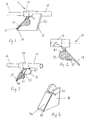
- Figure 1 illustrates a hose connecting device 11 that includes a carrier 13 which is firmly connected to an infusion hose 15.
- the carrier 13 is preferably in the form of a tubular element that has at one end a first internal diameter for attachment to the infusion hose and at its other end a second internal diameter for attachment to a supply hose 16.
- the carrier 13 also includes an angled part 17 that has an abutment surface 18 on one side thereof.
- the abutment surface 18 coacts with a coupling surface 19 on a supportive part 41.
- the supportive part is fixed to a peristaltic pump (not shown) in a conventional manner, via mounting means 42.
- Figure 1 thus shows the state of the hose connecting device when coupled to the supportive part.
- Figure 2 illustrates solely the hose connecting device 11 with the angled part 17 firmly connected to the carrier 13, said angled part defining an angled ⁇ with the carrier sign 13 wherein 180° ⁇ ⁇ ⁇ 90°.
- the illustrated angled part 17 is fixed to the carrier 13, said part may, alternatively be hinged to the carrier for angular movement within said angular range.
- the angled part 17 also includes gripping means 21 which extend at right angles outwardly from the angled part 17.
- the outwardly facing gripping surfaces 23 of the gripping means 21 are provided with friction enhancing means 25, for instance in the form of serrations.
- Figure 3 illustrates the carrier 13 with the fusion hose 15 and the supply hose 16 connected thereto.
- the figure also shows that the gripping means 21 connected to the angled part 17 include inwardly facing guide surfaces 31 that extend at right angles to the abutment surface 18.
- the abutment surface 18 of the angled part 17 is provided with a first coupling element 33.
- the supportive part 41 includes a coupling surface 43 which, in turn, is provided with a second coupling element 44.
- the first coupling element 33 on the abutment surface 18 is intended for co-action with the second coupling element 44 on said coupling surface such as to provide a coupling which will function to prevent relative movement between the coupling elements 33, 44 in a direction parallel with the coupling surface 43.
- inactivation of the coupling is permitted at a force which is at least equal to the tension force generated by the pump in said hose in a direction that has a mutual separating effect on the abutment surface and the coupling surface. Compare the assembled connected device 11 according to figure 1.
- the device also includes a slot 45 whose use originates from earlier coupling methods and which is preferably blocked to avoid cleaning problems.
- Figure 5 illustrates a hose connecting device in which the angled part 17 of the carrier 13 is provided with a gripping portion 51 in the form of an end piece protruding out from the angled part 17.
- This gripping portion enables the coupling to be readily released by drawing the abutment surface away from the coupling surface.
- the abutment surface 18 also includes a first coupling element 55.
- the gripping means 21 connected to the angled part 17 have smaller surfaces than the gripping means 21 of the first hose connecting device of figures 1-4.
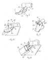
- Figure 6 illustrates a hose connecting device in which the carrier 13 includes two supply connections 61, 63 which merge with a pump connection 65.
- the angled part 17 of this hose connection device has the form shown in figure 5 in other respects, i.e. it includes a corresponding gripping part 51 and gripping means 21.
- Figure 7 illustrates a hose connecting device which, similar to the carrier 13 of the figure 6 device, includes two supply connections 61, 63 which merge with a pump connection 65.
- the angled part 17 of the figure 7 device has the form of the angled part shown in figures 1-3.
- the first and the second coupling devices shown in figures 1-7 are comprised of touch and close fasteners or of glue/tape applied to the coupling surface.
- the first and second coupling devices may comprise a magnet placed on either the abutment surface or on the coupling surface.
- Figure 8 illustrates a hose connecting device in which the carrier 13 includes a modified angled part 81, which also includes an abutment surface corresponding to that earlier described.
- the gripping means described with respect to the earlier devices function as guide surfaces 83 for centring an adapter sleeve 88 when mounting said sleeve to the supportive part 41.
- the adapter sleeve 88 includes a first coupling device 85 in the form of a pocket which defines, together with supportive part 41, a slot into which the angled part 81 can be pressed and retained so as to fixate the carrier to the coupling surface 43 of the supportive part 41.
- the guide surfaces 83 and the coupling device 85 are both arranged in the adapter sleeve 88, which is a permanent fixture on the supportive part 41.
- this device provides a hose coupling having a negative radial projection that is pushed down into a slot on the fixated adapter, wherewith the angle between carrier 13 and abutment surface 43 is ⁇ , where 180° ⁇ ⁇ ⁇ 90°.
- FIG. 9 illustrates an embodiment of a hose connecting device 91 according to the invention.
- the device is intended to be fitted to the coupling surface 43 of an existing supportive part 41 in accordance with each of the earlier described and illustrated devices, although fixedly mounted in the case of this embodiment.
- the device comprises a carrier 13 to which the hose (not shown) is connected, and an adapter sleeve 98 which is fixedly mounted to the supportive part 41.
- the adapter sleeve includes guide surfaces 93 and a cylindrical abutment surface 94 in a coupling part 92, into which the carrier 13 can be pressed and therewith fastened.
- the cylindrical fitting forms a clamping joint and may be provided internally with axial support means 95 in the form of an abutment surface against which the carrier abuts the bottom when fitted.
- Figure 10 illustrates a hose-connecting device that is intended to be fitted to the coupling surface 43 of an existing supportive part 41.
- a carrier 13 is intended for connection to an adapter sleeve 108 that includes guide surfaces 103 for centred fixed mounting of the sleeve to the supportive part 41.
- the adapter sleeve 108 includes two or more outwardly projecting corners, three such corners 104'. 104", 104'" in the case of the illustrated device, which are formed to abut the barrel surface of the carrier and/or engage with grooves 107 that include ring-shaped collars 105 formed in the carrier.
- the outer corners 104' are formed to abut the barrel surface of the carrier and/or engage with grooves 107 that include ring-shaped collars 105 formed in the carrier.
- abutment surface is formed between a collar 105 and one or more corners 104', 104", 104"'.
Landscapes
- Engineering & Computer Science (AREA)
- Health & Medical Sciences (AREA)
- Mechanical Engineering (AREA)
- General Engineering & Computer Science (AREA)
- Hematology (AREA)
- General Health & Medical Sciences (AREA)
- Biomedical Technology (AREA)
- Heart & Thoracic Surgery (AREA)
- Vascular Medicine (AREA)
- Life Sciences & Earth Sciences (AREA)
- Animal Behavior & Ethology (AREA)
- Anesthesiology (AREA)
- Public Health (AREA)
- Veterinary Medicine (AREA)
- Infusion, Injection, And Reservoir Apparatuses (AREA)
- Non-Disconnectible Joints And Screw-Threaded Joints (AREA)
- Reciprocating Pumps (AREA)
- Feeding And Controlling Fuel (AREA)
- Pipe Accessories (AREA)
Claims (3)
- Dispositif de raccordement de tuyaux (91) comprenant un élément porteur (13) fixé sur une tubulure de perfusion (15), élément porteur (13) qui est monté sur une partie de support (41) montée fixement sur une pompe péristaltique, caractérisé en ce que le dispositif de raccordement (91) comprend une partie de couplage (92) située sur un manchon (98), ce manchon (98) présentant la forme d'une partie qui forme un angle par rapport à l'axe de la partie de couplage (92), la partie formant un angle étant équipée d'un premier élément de couplage (33) coopérant avec un deuxième élément de couplage (44) sur une surface de couplage (43) fixée sur la partie de support (41) afin d'assurer une liaison fixe entre le manchon (98) et la partie de support (41), la partie de couplage (92) comprenant une surface de butée cylindrique (94) située dans l'élément de couplage (92) et destinée à coopérer avec l'élément porteur (13) afin de constituer une jonction par serrage.
- Dispositif de raccordement de tuyaux selon la revendication 1, caractérisé en ce que la surface de butée cylindrique (94) est pourvue, à l'intérieur, de moyens de support axiaux (95).
- Dispositif de raccordement de tuyaux selon l'une quelconque des revendications 1-2, caractérisé en ce que l'angle entre la direction axiale de l'élément porteur et la direction de la surface de butée (94) ou d'une surface de support présente sur le moyen de support (95) qui coopère avec l'élément porteur, est compris entre 90° et 180°.
Applications Claiming Priority (2)
| Application Number | Priority Date | Filing Date | Title |
|---|---|---|---|
| SE0302261A SE527048C2 (sv) | 2003-08-21 | 2003-08-21 | Slanganslutningsdon vid en peristaltisk pump |
| PCT/SE2004/001198 WO2005019648A1 (fr) | 2003-08-21 | 2004-08-16 | Dispositif de raccord de manchon |
Publications (2)
| Publication Number | Publication Date |
|---|---|
| EP1664536A1 EP1664536A1 (fr) | 2006-06-07 |
| EP1664536B1 true EP1664536B1 (fr) | 2007-10-17 |
Family
ID=28450274
Family Applications (1)
| Application Number | Title | Priority Date | Filing Date |
|---|---|---|---|
| EP04775311A Expired - Lifetime EP1664536B1 (fr) | 2003-08-21 | 2004-08-16 | Dispositif de raccord de manchon |
Country Status (5)
| Country | Link |
|---|---|
| EP (1) | EP1664536B1 (fr) |
| AT (1) | ATE376123T1 (fr) |
| DE (1) | DE602004009593T2 (fr) |
| SE (1) | SE527048C2 (fr) |
| WO (1) | WO2005019648A1 (fr) |
Cited By (2)
| Publication number | Priority date | Publication date | Assignee | Title |
|---|---|---|---|---|
| US11167081B2 (en) | 2016-06-16 | 2021-11-09 | Smiths Medical Asd, Inc. | Assemblies and methods for infusion pump system administration sets |
| US11801342B2 (en) | 2017-07-19 | 2023-10-31 | Smiths Medical Asd, Inc. | Housing arrangements for infusion pumps |
Families Citing this family (1)
| Publication number | Priority date | Publication date | Assignee | Title |
|---|---|---|---|---|
| ITMI20060766A1 (it) * | 2006-04-18 | 2007-10-19 | Mikai S P A | Sistema di collegamento dei tubi ad una pompa peristalica |
Family Cites Families (9)
| Publication number | Priority date | Publication date | Assignee | Title |
|---|---|---|---|---|
| US4184815A (en) * | 1977-03-14 | 1980-01-22 | Extracorporeal Medical Specialties, Inc. | Roller pump rotor with integral spring arms |
| DE8406203U1 (de) * | 1984-02-29 | 1984-05-30 | B. Braun Melsungen Ag, 3508 Melsungen | Infusions- und Transfusionsvorrichtung |
| US4997421A (en) * | 1986-12-10 | 1991-03-05 | Dale Medical Products, Inc. | IV connector lock and stabilizer |
| US4976590A (en) * | 1988-06-08 | 1990-12-11 | Baldwin Brian E | Fluid conduit-responsively adjustable pump arrangement and pump/conduit arrangement and method, and fluid conduits therefor |
| US5192273A (en) * | 1989-07-24 | 1993-03-09 | Steven F. Bierman | Catheterization system |
| ES2046760T3 (es) * | 1990-03-28 | 1994-02-01 | Fms Future Medical System Sa | Dispositivo para el montaje de una tuberia sobre una bomba peristaltica. |
| DE4222501C1 (fr) * | 1992-07-09 | 1993-07-01 | B. Braun Melsungen Ag, 3508 Melsungen, De | |
| GB2349431B (en) * | 1999-04-29 | 2002-06-12 | Watson Marlow Ltd | Peristaltic pumps |
| US6494864B1 (en) * | 2000-08-29 | 2002-12-17 | Sherwood Services, Ag | Inner lumen anti-free flow device |
-
2003
- 2003-08-21 SE SE0302261A patent/SE527048C2/sv unknown
-
2004
- 2004-08-16 DE DE602004009593T patent/DE602004009593T2/de not_active Expired - Lifetime
- 2004-08-16 EP EP04775311A patent/EP1664536B1/fr not_active Expired - Lifetime
- 2004-08-16 AT AT04775311T patent/ATE376123T1/de not_active IP Right Cessation
- 2004-08-16 WO PCT/SE2004/001198 patent/WO2005019648A1/fr not_active Ceased
Cited By (2)
| Publication number | Priority date | Publication date | Assignee | Title |
|---|---|---|---|---|
| US11167081B2 (en) | 2016-06-16 | 2021-11-09 | Smiths Medical Asd, Inc. | Assemblies and methods for infusion pump system administration sets |
| US11801342B2 (en) | 2017-07-19 | 2023-10-31 | Smiths Medical Asd, Inc. | Housing arrangements for infusion pumps |
Also Published As
| Publication number | Publication date |
|---|---|
| DE602004009593T2 (de) | 2008-07-31 |
| WO2005019648A1 (fr) | 2005-03-03 |
| SE0302261L (sv) | 2005-02-22 |
| ATE376123T1 (de) | 2007-11-15 |
| SE527048C2 (sv) | 2005-12-13 |
| DE602004009593D1 (de) | 2007-11-29 |
| EP1664536A1 (fr) | 2006-06-07 |
| SE0302261D0 (sv) | 2003-08-21 |
Similar Documents
| Publication | Publication Date | Title |
|---|---|---|
| US6173998B1 (en) | Plug-in coupling for connecting two fluid conduits | |
| US4786085A (en) | Coupling device for tubular members | |
| JP2758949B2 (ja) | 管継手スリーブ | |
| US6186561B1 (en) | Retainer for piping connector | |
| GB2263144A (en) | A plug-in pipe coupling with locking fingers and safety sleeve | |
| GB2236567A (en) | A hose coupling | |
| JPS62220794A (ja) | 解放可能な押込み式接手具 | |
| CN101201138A (zh) | 软管箍 | |
| CA2310770A1 (fr) | Raccord pivotant de tuyau flexible | |
| CA2114292A1 (fr) | Raccord a emboitement | |
| TW200907209A (en) | A coupling device for a fluid line | |
| EP1072837A3 (fr) | Raccord de tuyaux | |
| US20080100062A1 (en) | Coupling Device | |
| EP1664536B1 (fr) | Dispositif de raccord de manchon | |
| JP2007514108A (ja) | 波形管の端部に結合するための装置 | |
| DK0448909T3 (da) | Anordning til montering af en slange på en peristaltisk pumpe | |
| CN114127457B (zh) | 联接系统 | |
| US20040068846A1 (en) | Ring part comprising at least two partial rings and method for joining the partial rings to form a closed ring part | |
| PT941724E (pt) | Aparelhagem para ostomia | |
| RU2742514C1 (ru) | Быстроразъемный соединитель | |
| WO2000014445A1 (fr) | Ensemble de raccordement a raccorder a un tuyau | |
| TW200907210A (en) | A coupling device for a fluid line | |
| RU2715948C1 (ru) | Быстроразъемный соединитель | |
| CN207251835U (zh) | 扬声器或放大器框架的固定套件 | |
| US4696495A (en) | Pipe fitting assembly |
Legal Events
| Date | Code | Title | Description |
|---|---|---|---|
| PUAI | Public reference made under article 153(3) epc to a published international application that has entered the european phase |
Free format text: ORIGINAL CODE: 0009012 |
|
| 17P | Request for examination filed |
Effective date: 20060321 |
|
| AK | Designated contracting states |
Kind code of ref document: A1 Designated state(s): AT BE BG CH CY CZ DE DK EE ES FI FR GB GR HU IE IT LI LU MC NL PL PT RO SE SI SK TR |
|
| DAX | Request for extension of the european patent (deleted) | ||
| 17Q | First examination report despatched |
Effective date: 20061121 |
|
| RIN1 | Information on inventor provided before grant (corrected) |
Inventor name: MOELLSTAM, ANDERS Inventor name: PETTERSSON, INGVAR |
|
| GRAP | Despatch of communication of intention to grant a patent |
Free format text: ORIGINAL CODE: EPIDOSNIGR1 |
|
| RIN1 | Information on inventor provided before grant (corrected) |
Inventor name: MOELLSTAM, ANDERS Inventor name: PETTERSSON, INGVAR |
|
| GRAS | Grant fee paid |
Free format text: ORIGINAL CODE: EPIDOSNIGR3 |
|
| GRAA | (expected) grant |
Free format text: ORIGINAL CODE: 0009210 |
|
| AK | Designated contracting states |
Kind code of ref document: B1 Designated state(s): AT BE BG CH CY CZ DE DK EE ES FI FR GB GR HU IE IT LI LU MC NL PL PT RO SE SI SK TR |
|
| REG | Reference to a national code |
Ref country code: GB Ref legal event code: FG4D |
|
| REG | Reference to a national code |
Ref country code: CH Ref legal event code: EP |
|
| REG | Reference to a national code |
Ref country code: IE Ref legal event code: FG4D |
|
| REF | Corresponds to: |
Ref document number: 602004009593 Country of ref document: DE Date of ref document: 20071129 Kind code of ref document: P |
|
| ET | Fr: translation filed | ||
| NLV1 | Nl: lapsed or annulled due to failure to fulfill the requirements of art. 29p and 29m of the patents act | ||
| PG25 | Lapsed in a contracting state [announced via postgrant information from national office to epo] |
Ref country code: LI Free format text: LAPSE BECAUSE OF FAILURE TO SUBMIT A TRANSLATION OF THE DESCRIPTION OR TO PAY THE FEE WITHIN THE PRESCRIBED TIME-LIMIT Effective date: 20071017 Ref country code: CH Free format text: LAPSE BECAUSE OF FAILURE TO SUBMIT A TRANSLATION OF THE DESCRIPTION OR TO PAY THE FEE WITHIN THE PRESCRIBED TIME-LIMIT Effective date: 20071017 Ref country code: NL Free format text: LAPSE BECAUSE OF FAILURE TO SUBMIT A TRANSLATION OF THE DESCRIPTION OR TO PAY THE FEE WITHIN THE PRESCRIBED TIME-LIMIT Effective date: 20071017 Ref country code: ES Free format text: LAPSE BECAUSE OF FAILURE TO SUBMIT A TRANSLATION OF THE DESCRIPTION OR TO PAY THE FEE WITHIN THE PRESCRIBED TIME-LIMIT Effective date: 20080128 Ref country code: SE Free format text: LAPSE BECAUSE OF FAILURE TO SUBMIT A TRANSLATION OF THE DESCRIPTION OR TO PAY THE FEE WITHIN THE PRESCRIBED TIME-LIMIT Effective date: 20080117 |
|
| REG | Reference to a national code |
Ref country code: CH Ref legal event code: PL |
|
| PG25 | Lapsed in a contracting state [announced via postgrant information from national office to epo] |
Ref country code: PT Free format text: LAPSE BECAUSE OF FAILURE TO SUBMIT A TRANSLATION OF THE DESCRIPTION OR TO PAY THE FEE WITHIN THE PRESCRIBED TIME-LIMIT Effective date: 20080317 Ref country code: PL Free format text: LAPSE BECAUSE OF FAILURE TO SUBMIT A TRANSLATION OF THE DESCRIPTION OR TO PAY THE FEE WITHIN THE PRESCRIBED TIME-LIMIT Effective date: 20071017 Ref country code: SI Free format text: LAPSE BECAUSE OF FAILURE TO SUBMIT A TRANSLATION OF THE DESCRIPTION OR TO PAY THE FEE WITHIN THE PRESCRIBED TIME-LIMIT Effective date: 20071017 Ref country code: BG Free format text: LAPSE BECAUSE OF FAILURE TO SUBMIT A TRANSLATION OF THE DESCRIPTION OR TO PAY THE FEE WITHIN THE PRESCRIBED TIME-LIMIT Effective date: 20080117 |
|
| PG25 | Lapsed in a contracting state [announced via postgrant information from national office to epo] |
Ref country code: AT Free format text: LAPSE BECAUSE OF FAILURE TO SUBMIT A TRANSLATION OF THE DESCRIPTION OR TO PAY THE FEE WITHIN THE PRESCRIBED TIME-LIMIT Effective date: 20071017 |
|
| PG25 | Lapsed in a contracting state [announced via postgrant information from national office to epo] |
Ref country code: CZ Free format text: LAPSE BECAUSE OF FAILURE TO SUBMIT A TRANSLATION OF THE DESCRIPTION OR TO PAY THE FEE WITHIN THE PRESCRIBED TIME-LIMIT Effective date: 20071017 Ref country code: DK Free format text: LAPSE BECAUSE OF FAILURE TO SUBMIT A TRANSLATION OF THE DESCRIPTION OR TO PAY THE FEE WITHIN THE PRESCRIBED TIME-LIMIT Effective date: 20071017 |
|
| PLBE | No opposition filed within time limit |
Free format text: ORIGINAL CODE: 0009261 |
|
| STAA | Information on the status of an ep patent application or granted ep patent |
Free format text: STATUS: NO OPPOSITION FILED WITHIN TIME LIMIT |
|
| PG25 | Lapsed in a contracting state [announced via postgrant information from national office to epo] |
Ref country code: SK Free format text: LAPSE BECAUSE OF FAILURE TO SUBMIT A TRANSLATION OF THE DESCRIPTION OR TO PAY THE FEE WITHIN THE PRESCRIBED TIME-LIMIT Effective date: 20071017 Ref country code: BE Free format text: LAPSE BECAUSE OF FAILURE TO SUBMIT A TRANSLATION OF THE DESCRIPTION OR TO PAY THE FEE WITHIN THE PRESCRIBED TIME-LIMIT Effective date: 20071017 Ref country code: RO Free format text: LAPSE BECAUSE OF FAILURE TO SUBMIT A TRANSLATION OF THE DESCRIPTION OR TO PAY THE FEE WITHIN THE PRESCRIBED TIME-LIMIT Effective date: 20071017 |
|
| 26N | No opposition filed |
Effective date: 20080718 |
|
| PG25 | Lapsed in a contracting state [announced via postgrant information from national office to epo] |
Ref country code: GR Free format text: LAPSE BECAUSE OF FAILURE TO SUBMIT A TRANSLATION OF THE DESCRIPTION OR TO PAY THE FEE WITHIN THE PRESCRIBED TIME-LIMIT Effective date: 20080118 |
|
| PG25 | Lapsed in a contracting state [announced via postgrant information from national office to epo] |
Ref country code: FI Free format text: LAPSE BECAUSE OF FAILURE TO SUBMIT A TRANSLATION OF THE DESCRIPTION OR TO PAY THE FEE WITHIN THE PRESCRIBED TIME-LIMIT Effective date: 20071017 |
|
| PG25 | Lapsed in a contracting state [announced via postgrant information from national office to epo] |
Ref country code: MC Free format text: LAPSE BECAUSE OF NON-PAYMENT OF DUE FEES Effective date: 20080831 |
|
| PG25 | Lapsed in a contracting state [announced via postgrant information from national office to epo] |
Ref country code: EE Free format text: LAPSE BECAUSE OF FAILURE TO SUBMIT A TRANSLATION OF THE DESCRIPTION OR TO PAY THE FEE WITHIN THE PRESCRIBED TIME-LIMIT Effective date: 20071017 |
|
| PG25 | Lapsed in a contracting state [announced via postgrant information from national office to epo] |
Ref country code: CY Free format text: LAPSE BECAUSE OF FAILURE TO SUBMIT A TRANSLATION OF THE DESCRIPTION OR TO PAY THE FEE WITHIN THE PRESCRIBED TIME-LIMIT Effective date: 20071017 Ref country code: IE Free format text: LAPSE BECAUSE OF NON-PAYMENT OF DUE FEES Effective date: 20080818 |
|
| PG25 | Lapsed in a contracting state [announced via postgrant information from national office to epo] |
Ref country code: LU Free format text: LAPSE BECAUSE OF NON-PAYMENT OF DUE FEES Effective date: 20080816 Ref country code: HU Free format text: LAPSE BECAUSE OF FAILURE TO SUBMIT A TRANSLATION OF THE DESCRIPTION OR TO PAY THE FEE WITHIN THE PRESCRIBED TIME-LIMIT Effective date: 20080418 |
|
| PG25 | Lapsed in a contracting state [announced via postgrant information from national office to epo] |
Ref country code: TR Free format text: LAPSE BECAUSE OF FAILURE TO SUBMIT A TRANSLATION OF THE DESCRIPTION OR TO PAY THE FEE WITHIN THE PRESCRIBED TIME-LIMIT Effective date: 20071017 |
|
| PG25 | Lapsed in a contracting state [announced via postgrant information from national office to epo] |
Ref country code: IT Free format text: LAPSE BECAUSE OF NON-PAYMENT OF DUE FEES Effective date: 20080831 |
|
| REG | Reference to a national code |
Ref country code: DE Ref legal event code: R082 Ref document number: 602004009593 Country of ref document: DE Representative=s name: GRUENECKER, KINKELDEY, STOCKMAIR & SCHWANHAEUS, DE Ref country code: DE Ref legal event code: R082 Ref document number: 602004009593 Country of ref document: DE Representative=s name: GRUENECKER PATENT- UND RECHTSANWAELTE PARTG MB, DE |
|
| REG | Reference to a national code |
Ref country code: FR Ref legal event code: PLFP Year of fee payment: 13 |
|
| PGFP | Annual fee paid to national office [announced via postgrant information from national office to epo] |
Ref country code: GB Payment date: 20160810 Year of fee payment: 13 Ref country code: DE Payment date: 20160809 Year of fee payment: 13 |
|
| PGFP | Annual fee paid to national office [announced via postgrant information from national office to epo] |
Ref country code: FR Payment date: 20160712 Year of fee payment: 13 |
|
| REG | Reference to a national code |
Ref country code: DE Ref legal event code: R119 Ref document number: 602004009593 Country of ref document: DE |
|
| GBPC | Gb: european patent ceased through non-payment of renewal fee |
Effective date: 20170816 |
|
| REG | Reference to a national code |
Ref country code: FR Ref legal event code: ST Effective date: 20180430 |
|
| PG25 | Lapsed in a contracting state [announced via postgrant information from national office to epo] |
Ref country code: GB Free format text: LAPSE BECAUSE OF NON-PAYMENT OF DUE FEES Effective date: 20170816 Ref country code: DE Free format text: LAPSE BECAUSE OF NON-PAYMENT OF DUE FEES Effective date: 20180301 |
|
| PG25 | Lapsed in a contracting state [announced via postgrant information from national office to epo] |
Ref country code: FR Free format text: LAPSE BECAUSE OF NON-PAYMENT OF DUE FEES Effective date: 20170831 |