EP1664593B1 - Embrayage de pontage pour composants hydrodynamiques - Google Patents
Embrayage de pontage pour composants hydrodynamiques Download PDFInfo
- Publication number
- EP1664593B1 EP1664593B1 EP04786967A EP04786967A EP1664593B1 EP 1664593 B1 EP1664593 B1 EP 1664593B1 EP 04786967 A EP04786967 A EP 04786967A EP 04786967 A EP04786967 A EP 04786967A EP 1664593 B1 EP1664593 B1 EP 1664593B1
- Authority
- EP
- European Patent Office
- Prior art keywords
- countershaft
- lockup clutch
- output
- wheel
- clutch arrangement
- Prior art date
- Legal status (The legal status is an assumption and is not a legal conclusion. Google has not performed a legal analysis and makes no representation as to the accuracy of the status listed.)
- Expired - Lifetime
Links
Images


Classifications
-
- F—MECHANICAL ENGINEERING; LIGHTING; HEATING; WEAPONS; BLASTING
- F16—ENGINEERING ELEMENTS AND UNITS; GENERAL MEASURES FOR PRODUCING AND MAINTAINING EFFECTIVE FUNCTIONING OF MACHINES OR INSTALLATIONS; THERMAL INSULATION IN GENERAL
- F16H—GEARING
- F16H47/00—Combinations of mechanical gearing with fluid clutches or fluid gearing
- F16H47/06—Combinations of mechanical gearing with fluid clutches or fluid gearing the fluid gearing being of the hydrokinetic type
Definitions
- the invention relates to a bridging circuit for hydrodynamic components, in particular for coupling with downstream gear ratios of a transmission, in detail with the features of the preamble of claim 1.
- Die FR-A-1000870 is considered the closest prior art.
- Hydrodynamic components as starting components are known in a variety of designs for a wide variety of transmission types. All have in common, however, that they are usually effective only over part of the entire operating range of the transmission, that is transmitted power.
- the advantageous properties of the hydrodynamic components which may take the form of hydrodynamic clutches or hydrodynamic speed / torque converters, are utilized during the starting process. If the disadvantageous properties over the mechanical power transmission predominate, the hydrodynamic components are bypassed, ie the power flow no longer takes place via the hydrodynamic component.
- the bridging takes place by coupling the secondary wheel to the primary wheel, preferably non-rotatable rigid coupling, but also slippy embodiments are conceivable.
- bridging clutches are generally used, which are preferably designed in lamella type.
- the hydrodynamic component is no longer involved in the power transmission, but is dragged along because of the rigid coupling. This can either remain filled when removed from the power flow or is preferably emptied. It is usually necessary for the manufacturer of the hydrodynamic component to take into account the space for the lock-up clutch with. Furthermore, the manufacturer of the lock-up clutch is bound to the present circumstances of the hydrodynamic component. The entire element is delivered as a so-called starting unit completely pre-assembled. Since the lock-up clutch is usually a frictionally engaged clutch, efficiency losses are recorded. Furthermore, it is a component subject to wear, which must be replaced after a certain period of operation and dimensioned with regard to the specific mode of operation in order to regularly avoid overloading.
- Transmission units in particular automatic transmission with a starting element and a bridging clutch and a the starting element and the lock-up clutch downstream speed / torque conversion unit, which is characterized by at least one gear, are already known in a variety of versions .. In this regard, for example, reference is made to the following references. FR 2 719 355 DE 949 990 DE 972 489 US 3,442,155 DE 960 529
- the hydrodynamic speed / torque converter is always in the power flow, which is However, just in terms of the main work area of such a gear unit as negative in terms of efficiency and further no Schubmomentübertragungsdorfkeit is given due to the intermediate freewheel to the drive machine.
- the power transmission takes place via appropriate countershaft, whereby depending on the desired gradation and desired power to be transmitted appropriate gear ratios are provided.
- the possible number of gears is predetermined in such a transmission, so that any extension leads to the inclusion of additional gear ratios in the transmission. This has the consequence that the axial length increases considerably. Other modifications that have a size change in the radial direction result would also be conceivable, but are very expensive.
- the invention is therefore based on the object to provide a way of bridging a hydrodynamic component, in particular a hydrodynamic coupling, which is not bound to the structural conditions of the hydrodynamic component, and also in combination with at least one speed / torque converter, in particular individual gear stages, having advantageous properties. It should be ensured that the possibility exists in combination with downstream switching stages, if necessary, to drive all gears either via the starting element or bypassing the starting element.
- the hydrodynamic component comprising at least one primary wheel which can be coupled to a drive, preferably a coupled primary wheel and a secondary wheel which can be connected to at least one speed / torque converter, is assigned a bridging circuit which comprises two inputs and at least one output.
- a first input of the bridging circuit is rotatably connected to the secondary, while the second input is rotatably coupled to the primary wheel.
- the first power branch is characterized by the connection between the first input and the output and is used for power transmission via the hydrodynamic component.
- the second power branch is characterized by the coupling between the primary wheel and the output of the bypass circuit, in which case the hydrodynamic component is bypassed in the power flow.
- At least one switchable clutch device For selectively coupling the first or second power branch to the output or to the speed / torque converter devices which can be coupled thereto, at least one switchable clutch device is provided.
- This comprises either a two power branches common associated clutch, which is characterized by at least two switching positions, wherein in the first switching position of the first input to the output at least indirectly rotatably connected, while in the second switching position of the second input is coupled to the output, said In this switching position, the hydrodynamic component is free from a rotationally fixed coupling between the primary wheel and the secondary wheel. This means in detail that the hydrodynamic component is taken out of the power flow and at least the secondary wheel no longer has to co-rotate with mechanical power transmission, ie is no longer positively coupled.
- the switchable coupling device comprises two clutches.
- the bridging of the hydrodynamic component itself is thus not only immediate, but can be made in any place this downstream in the power flow. This makes it possible to shift the bridging in a transmission when the hydrodynamic component is designed as a separate unit.
- the bridging circuit comprises a first counterrotation connected to the secondary wheel in a rotationally fixed manner and a second countershaft connected in a rotationally fixed manner to the primary wheel.
- the counter can also are referred to as speed / torque conversion means and serve to connect eccentric to each other arranged waves or other rotating elements.
- Both countershafts are selectively connectable to the output of the lock-up circuit via the shiftable clutch device, comprising either a shift clutch jointly assigned to two forwards or two clutches, ie separately assigned to each countershaft and separately or jointly controllable. With coaxial arrangement of the input and output of the bypass circuit or eccentric arrangement to the output of the two countershaft, the connection is made via a further third countershaft.
- different gear stages realizing speed and torque converter means can be coupled, wherein the counter gear ratio of the third counter gear can also be used as a gear ratio.
- the third countershaft is decoupled from the output via a second clutch device, comprising a clutch. If, however, the output of the bridging circuit is formed directly by the countershaft coupled to the speed / torque converter devices of the bridging circuit, different gear stages can be realized via the latter or with the third third countershaft that can be connected to it in a torque-proof manner.
- the switchable coupling device is arranged between the first and second countershaft either coaxially or parallel or eccentrically to a theoretical axis through the input of the combination of hydrodynamic component and bridging circuit, the input of the combination of the primary wheel or at least indirectly from the second input of the Bypass circuit is formed.
- the switchable coupling serves to couple a parallel to the input arranged countershaft with the two present - first countershaft and second countershaft - and the countershaft with the downstream switching stages, the output of the lock-up circuit is formed either directly from the countershaft and the subsequent stages then preferably be coupled with the actual transmission output further third Vorgelegen with different translation or the connection to the subsequent gear stages is still realized via a further translation in the form of a non-decoupled third Vorgeleges, which is rotatably connected to the output.
- the third countershaft is the return to an input shaft of any gear ratios forming gear unit, for example in planetary construction.
- a bypass of the hydrodynamic component is made possible with the desired purely mechanical power transmission, which is free from a rotationally fixed coupling between the primary wheel and the secondary wheel.
- the secondary wheel can run freely in this case and is free of a support against a rotating or stationary element. This can be done with filled hydrodynamic component.
- the first and the second countershaft are arranged coaxially and parallel to each other.
- the arrangement of the first and the second Vorgeleges takes place in the axial direction side by side.
- the input of the module is thereby formed by the primary wheel or a member rotatably connected thereto or the first input of the bypass circuit.
- the output of the hydrodynamic component assembly and bypass circuit is formed by the output of the bypass circuit. This is used for coupling with downstream speed / torque converter.
- the arrangement of the first countershaft takes place before the second countershaft.
- Other possibilities are conceivable.
- these are designed as simple Stirnrad accounts.
- These each comprise two intermeshing spur gears, wherein a respective first spur gear rotatably connected to the secondary gear or for the second countershaft rotatably connected to the primary wheel, while each with these intermeshing second spur gears rotatably coupled via the first switchable coupling with the countershaft.
- This also applies to the third countershaft, which is rotatably coupled to the countershaft and can be connected or connected to the output A in a torque-proof manner.
- a translation is selected , which takes into account the slip of the hydrodynamic coupling. This is based on a certain predefined slip value, which is characterized by a certain predefined permissible speed difference between the primary wheel and the secondary wheel.
- the dimensioning of the second countershaft is such that a certain speed difference is compensated for the secondary and coupled to these first countershaft by rotating at this both outputs of the two countershaft with the same speed and thus the required speed equality to synchronously switchable clutches the To change power flow path. Due to the resulting by the different ratios at the outputs of the counterparts same speed can be done easily in this state, a circuit between the first and second countershaft.
- the dimensioning, in particular design of the spur gears in terms of number of teeth, diameter and the intervention determining parameters is thus a function of a certain predefined speed difference, in which a bridging should take place.
- At least one of the two power branches associated switchable coupling device comprising either a two Vorgelegen (first and second) jointly assigned switchable coupling, which is arranged between the two present and optionally the rotationally fixed coupling of the first counterset with the countershaft or but the second countershaft with the countershaft is used or each countershift separately associated clutch.
- this is assigned to both Vorgelegen a jointly mutually usable switchable clutch.
- assign each of the countershaft or power branches their own switchable clutch, which are individually controllable, but the operation should be coordinated.
- the couplings can be arranged both coaxial with the starting element and eccentrically to this.
- the arrangement can take place at any point in the power path of the individual power branches, i. the arrangement can be coaxial as well as eccentric to the countershaft. In this case, theoretically it is also possible when assigning a switchable coupling to a power branch to carry out the arrangement at different positions in the two power branches.
- This coupling is referred to here as the third clutch.
- the third clutch allows a direct rotationally fixed coupling between the inputs and the output of the bypass circuit, which is coaxial with the input and output of the module, but at least the hydrodynamic component.
- the direct coupling is preferably carried out outside the power branches.
- a through drive between the input and output of the assembly of hydrodynamic component and bridging circuit can be realized, which is when coupled with subsequent gear stages of a direct gear with a ratio of 1: 1 speaks.
- the power flow takes place directly between input and output coaxial and not via other transmission elements.
- This shift position is selected for the through drive in direct gear, in which case the two the connections between the inputs of the lock-up circuit with the countershaft and the countershaft with the output of the lock-up circuit realizing clutches, switchable clutch and second shiftable clutch, are open in this state and thus the countershaft is decoupled from the input or output.
- a power transmission is realized with optimum efficiency in the direct drive.
- To switch the third shiftable clutch can also be done, an adjustment of the speeds between input and output, preferably by reducing the drive motor speed.
- a brake device is also assigned to the secondary wheel.
- This serves to decelerate or preferably fixing the secondary wheel, wherein in mechanical power transmission, the hydrodynamic coupling acts as a hydrodynamic retarder when filled, in which the output via the third and second countershaft or in direct coupling with the primary wheel acting as a secondary stator is supported ,
- synchronously switchable, positive clutches are used to reduce wear as a switchable clutches, which in turn are preferably designed as a claw coupling. Designs with non-positive clutches are also conceivable.
- the arrangement is coaxial.
- Bridging circuit and hydrodynamic component can be designed as a structural unit or separate units.
- the lock-up circuit can also be combined with this downstream speed / torque converter to form a structural unit.
- the formation of the hydrodynamic component is almost independent of the transmission including the speed / torque converter.
- the hydrodynamic component can be designed as a hydrodynamic coupling free of a stator or hydrodynamic speed / torque converter.
- the latter additionally comprises at least one stator.
- the realization of the speed equality with the desired bridging between the two outputs of first and second countershaft by taking into account the slip, ie in particular the speed difference between the primary and secondary of the hydrodynamic component for the state in which a bridging is desired, at the dimensioning of the individual countershaft.
- a certain predefined slip value on the hydrodynamic component is taken as the basis, which can be chosen freely or is characterized by the performance characteristics of the hydrodynamic component (for example about 20%), which would still allow an optimal operation in terms of efficiency, and the one characterized certain predefined speed difference between primary and secondary.
- This speed difference is taken into account in the design of the two countershaft, so that this is taken into account at the outputs, in particular the gear wheels which can be coupled to the countershaft arranged parallel or eccentrically relative to the hydrodynamic component.
- the dimensioning of the individual intermeshing spur gears in terms of their dimensions and number of teeth and / or tooth shape and design is obtained as a function of the speed difference n P - n T between the primary and secondary.
- the dimensioning, in particular design of the individual spur gears in terms of number of teeth, diameter and / or the parameters determining the engagement is defined as a function of the speed difference at which a bridging is to take place.
- the slip in the gear ratios different possibilities are conceivable. This can for example be done solely by changing the pitch of the individual spur gears with the same diameter, in particular head diameter, root diameter or average diameter, in these cases, the tooth width is varied substantially.
- a plurality, preferably all the teeth of a spur gear characterizing parameters adapted and changed in a corresponding manner Preferably, however, always solutions are chosen, which are distinguished by optimal structural efficiency and low structural modifications and which can be used on standardized components.
- the first and the second countershaft are arranged coaxially and parallel to each other.
- the arrangement of the first and the second Vorge privileges takes place in the axial direction side by side.
- the input of the module is thereby rotationally fixed by the primary wheel or one with this connected element or the first input of the bypass circuit formed.
- the output of the imageable hydrodynamic component and bypass circuit is formed by the output of the bypass circuit. This is used for coupling with downstream speed / torque converter.
- the arrangement of the first countershaft takes place before the second countershaft.
- Other possibilities are conceivable.
- the countershaft there are a multitude of possibilities.
- these are designed as simple Stirnrad accounts.
- These each comprise two intermeshing spur gears, wherein a respective first spur gear rotatably connected to the secondary gear or for the second countershaft rotatably connected to the primary wheel, while each with these intermeshing second spur gears rotatably coupled via the first switchable coupling with the countershaft.
- This also applies to the countershaft rotatably coupled or preferably rotatably coupled third countershaft, which in turn rotatably connected to the output A of the bridging GmbHu ng or connected or the grades of the nachordenbaren transmission descriptive single countershaft in the case of the formation of the output of the bypass circuit from the countershaft.
- a freewheel is provided between the secondary wheel and the front of the lock-up circuit.
- This is also considered the connection of the braking device to the secondary in the power flow direction between the input and output of the starting element, downstream.
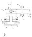
- FIG. 1 a illustrates in schematically simplified representation of the basic principle and the basic structure of an inventively designed lock-up circuit 1, which is assigned to a hydrodynamic component 2. Both form an assembly 25 in combination with each other.
- the hydrodynamic component 2 is in this case designed as a hydrodynamic coupling 3.
- the latter comprises at least one primary wheel 4, which can be connected at least indirectly with a drive 31, and at least indirectly rotatable connected secondary wheel 5.
- the primary wheel 4 forms an input 29 of the module 25.
- the secondary wheel 5 is at least indirectly connected to the output 30 the assembly 25 connectable. This coupling takes place via the bridging circuit 1.
- Input 29 and output 30 are preferably, however, not necessarily arranged coaxially.
- Primary wheel 4 and secondary wheel 5 thereby form a working space 6 which can be filled with operating medium.
- the bridging arrangement 1 comprises two inputs, a first input 26, which is connected to the Secondary wheel 5 at least directly, that is rotatably connected directly or via further elements, and a second input 27, which is connected at least indirectly, ie directly or via further elements rotatably connected to the primary wheel 4. Further provided is an output 28 which forms the output of the assembly 25.
- Each input 26 or 27 is selectively connectable to the output 28 via transmission elements.
- two power branches are generated, a first power branch 32 and a second power branch 33.
- the first power branch is characterized by the exclusive transmission of power on a hydrodynamic path.
- the second power path is characterized by purely mechanical power transmission.
- the coupling takes place optionally, ie in each case only one input is connected to the output 28.
- the bridging circuit 1 comprises two countershaft, a first countershaft 7 and a second countershaft 8.
- the first countershaft 7 is rotatably connected to the secondary wheel 5.
- the second countershaft 8 is rotatably connected to the primary wheel 4.
- the connection takes place at least indirectly, ie either directly with the corresponding components or via further rotatably coupled thereto elements.
- a switchable coupling 18 arranged between the first countershaft 7 and the second countershaft 8 is also provided, which optionally enables the coupling between the first countershaft 7 or the second countershaft 8 with a countershaft 10 coupled via a third countershaft 9.
- the individual countershaft, first countershaft 7, second countershaft 8 and third countershaft 9 are preferably designed as Stirnrad accounts. These are designated for the first countershaft 7 with 11, for the second countershaft 8 with 12 and for the third countershaft 9 with 13.
- the pinions 14 and 15 of the spur gear sets 11 and 12 of the first countershaft 7 and the second countershaft 8 are in each case rotatably connected as described with the primary wheel 4 and the secondary wheel 5.
- the coupling with these spur gears 16 for the spur gear set 11 of the first countershaft 7 and 17 of the spur gear set 12 of the second intermediate gear 8 are selectively connected via the switchable clutch 18 of the countershaft 10.
- the switchable coupling 18 is arranged parallel to the input 29 or to the primary wheel 4 or secondary wheel 5.
- the countershaft 10 can as a full or Be executed hollow shaft. This is arranged parallel to a theoretical axis between input 29 and output 28 and to the hydrodynamic coupling 3. This is rotatably connected to a spur gear 21 of the spur gear 13 of the third countershaft 9 according to a first embodiment. The meshing with this spur gear 19 spur gear 21 of the third countershaft 9 is rotatably connected to the output 28, in particular the shaft 20 formed by this.
- the switchable coupling 18 provided for bypassing the power flow via the hydrodynamic component 2, in particular the hydrodynamic coupling 3, is therefore not arranged coaxially with the hydrodynamic coupling 3, but is parallel or eccentric.
- the power flow takes place here in the traction mode viewed from the input 29 in the direction of the output 30 via the non-rotatably coupled to the primary gear 4 second countershaft 8, in particular the pinion 15 on the spur gear 17, the countershaft 10, the spur gear 19, 21 and from this on the rotatably coupled with this shaft or another with this rotatably coupled element.
- This power flow is in Figure 1c shown.
- the hydrodynamic coupling is taken out of the power flow in this state and only the primary wheel 4 entrained.
- the secondary wheel 5 is completely decoupled.
- the clutch 3 can therefore remain filled.
- the hydrodynamic component 2, in particular the hydrodynamic coupling 3, is used as a hydrodynamic retarder.
- a brake device 22 is assigned in the secondary 5, which may be designed in many forms. This serves to fix the secondary wheel 5.
- the secondary wheel 5 is designed as a stator in this functional state. The output A is thus based on the two countershaft, third countershaft 9 and second countershaft 8 and with this rotatably connected primary wheel 4 on the stator, which is formed by the secondary 5 from.
- the power flow over the countershaft, in particular the countershaft 7, 8 and 9 allow for coupling of the hydrodynamic clutch 3 with lock-up arrangement 1 with the gear ratios of a transmission a reduction in the individual gear ratios.
- different translations can be accommodated depending on the interpretation of the transmission ratio in the present, however, a worse efficiency is also to be expected in the usually desired 1: 1 ratio due to the transmission of power via the countershaft 7, 8.
- a further third clutch 24 between the second and the third countershaft 8 and 9, which is switchable and coaxial with the hydrodynamic Kupplu ng 3 and the input 29 and the output 30 of the assembly 25 and the inputs 26, 27 and the output 28 of Bypass circuit 1 is arranged.
- This third clutch 24 allows the direct mechanical drive from the input 29 to the output 30 and the inputs 26, 27 to the output 28 free of the leadership of other speed / torque converter devices. The speed and the torque at the input 29 corresponds to when switching the clutch 24 those at the output.
- a further second switchable coupling 23 is further provided for decoupling of the third countershaft 9 of the countershaft 10.
- the switchable clutches in particular the shiftable clutch 18 and 23 and 24, preferably as positive synchronous switchable clutches, preferably in the form of jaw clutches executed.
- Other versions, in particular in the form of non-positive clutches are also conceivable. However, these work with slippage, whereby the efficiency of the overall system is reduced. Therefore, according to the invention preferably form-fitting, synchronously switchable couplings are used.
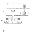
- FIG. 2b clarified for the execution according to FIG. 2a the power flow of the hydrodynamic component 2 during the starting process, that is in hydrodynamic operation.
- the hydrodynamic component 2 is filled with resources.
- the power flow takes place via the hydrodynamic component 2, in particular the hydrodynamic clutch 3.
- the first shiftable clutch 18 is in the shift position I 18 , ie, this realizes the rotationally fixed connection between the first countershaft 7, in particular the spur gear 16 with the countershaft 10th
- the second countershaft 8 is decoupled from the countershaft 10.
- the second clutch 23 is also in this first shift position I 23 , in which a rotationally fixed connection with the countershaft 10 is realized.
- the third shiftable clutch 24 is in the second shift position II 24 , that is, dissolved or opened.
- the power flow takes place from the input 29 via the primary wheel 4, the secondary 5 to the first countershaft 7, in particular the pinion 14, the spur gear 16 to the countershaft 10, the third countershaft 9, in particular the spur gear 21 and the rotationally fixed to the shaft 20th Coupled spur gear 19.
- the switching or bridging of the hydrodynamic component 2, in particular the hydrodynamic coupling 3, takes place by the change of the power path, in particular by switching the first switchable clutch 18, wherein this in the shift position III 18 according to Figure 2c is spent, which allows a rotationally fixed connection with the second countershaft 8 and the countershaft 10.
- the first countershaft 7 is decoupled from the countershaft 10.
- the second clutch 23 remains in its first shift position I 23 , ie the realization of the rotationally fixed connection between the third countershaft 9 and the countershaft 10.
- the switching takes place by a targeted reduction of the speed at the input 29 and the input 27 of the lock-up circuit, in particular the coupled with this rotationally fixed drive machine and the slip-transmitting hydrodynamic Clutch 3, to achieve a speed equality between the spur gears 16 and 17 of the countershaft 7 and 8.
- the resulting in the switching position III 18 of the first switchable clutch 18 power flow, bypassing the hydrodynamic component 2, in particular the hydrodynamic coupling 3 resulting power flow, is in the Figure 2c shown.
- the Figure 2d clarifies contrast, the possible use of the third clutch 24 power transmission with a translation of 1: 1 between the input 29 and the output 30 of the module 25 and the inputs 26 and 27 of the bypass circuit 1 and the output 28.
- the switchable Clutch 24 is closed, that is, is in the first switching position I 24 , which rotatably connects the input 27, in particular the second countershaft 8 with the third countershaft 9, in particular the pinion 15 with the spur gear 19.
- the first shiftable clutch 18 and the second shiftable clutch 23 are opened in this functional state, ie, 18 or II 23 are in the shift position II.
- the power transmission takes place coaxially between input 29 and output 30 of the assembly 25 free from transmission via speed / torque converter.
- the input 29 is rigidly coupled to the output 30.
- FIG. 2e illustrates the realization of the braking operation in the so-called direct gear, ie power transmission from the input 29 to the output 30.
- the third clutch 24 is closed, while the other two clutches 18 and 23 are open and thus the individual countershaft, in particular the countershaft 7, the eighth and decouple 9 from the output 30 or 28 of the bypass circuit 1.
- the output 30 or 28 and with These connected speed / torque converter devices are supported in this functional state via the primary wheel 4 on the secondary wheel 5 acting as a stator.
- the latter is determined by actuation of the brake device 22, preferably on a round component. This can be achieved in all mechanical gears always a braking effect, which can be realized due to the direct drive with the highest possible translation.
- FIGS. 1 and 2 illustrated embodiments and modes of operation were chosen for the first countershaft 7 and the second countershaft 8 equal translations.
- FIG. 3 according to an embodiment according to FIG. 2a shown to make a circuit without speed adjustment of the input 29 and the input 27 directly coupled primary wheel 4 and at the same time to achieve an improvement in acceleration by a higher tensile force in the mechanics.
- the counter gear ratio between the first countershaft 7 and the second countershaft 8 is changed by the slip amount at which one wishes to bridge. This means in detail that with constant translation for the first countershaft 7, the translation on the second countershaft 8 is reduced.
- both countershaft are executed with different translation, wherein at power transmission through the hydrodynamic component 2 at a certain preselected speed difference between the primary 4 and secondary 5, resulting in a speed equality at the outputs of the countershaft 7 and 8, in particular the rotational speeds of the spur gears 16th precipitated.
- the design of the countershaft 7 and 8 is such that due to the present at slip on the secondary wheel at lower speed compared to the primary wheel, the speed of the primary wheel 4 via the countershaft 7 rotatably connected element, which at least indirectly rotationally fixed on the switchable coupling with the output 28th the lock-up circuit 1 is connectable, is reduced or the speed of the coupled to the secondary output of the first countershaft is increased.
- the corresponding translation as a function of the slip to be compensated is selected according to the common teachings. This is done by appropriate dimensioning of the gears, the teeth and the engagement geometry. It is possible, depending on the size of the slip value to be compensated, ie the speed difference to be compensated either to affect only the pitch or the overall geometry, in particular the diameter and number of teeth of the spur gears.
- the concrete measure lies at the discretion of the responsible expert.
- the amount of slip, ie the speed difference at which is bridged, is determined or selected depending on the properties of the hydrodynamic component.
- the hydrodynamic coupling 1 preferably remains at least partially filled. The functionality is like in the FIGS. 1 and 2 described.
- FIGS. 1 to 3 represent only basic variants and advantageous embodiments of the It is only essential that different modes of operation can be realized by switching two power paths, wherein in the functional state of bypassing the hydrodynamic component, a mechanical power transmission takes place, which is free from a direct rotationally fixed coupling between the primary and secondary of the hydrodynamic component.
- the performance is carried out in the realization of the two power branches not directly coaxial, but parallel to the theoretical axis of rotation of the hydrodynamic component.
- Hydrodynamic couplings or hydrodynamic speed / torque converters can be used as the hydrodynamic component.
- FIGS. 1 to 4 clarify explanations with a two co-located jointly assigned clutch, which is arranged coaxially to the countershaft.
- a shared coupling device coaxial with the starting element as well as versions with two switchable couplings, which are assigned to one of the two countershaft and can be arranged at any position in the power flow (coaxial with the starting element or the countershaft or eccentric to these).
- switchable couplings find, as already stated, synchronously switchable form-liquid couplings use in a particularly advantageous manner. This means that it is completely dispensed with frictional coupling elements. The required speed adjustments for the realization of the switching process are made via the control technology.
- the inventively designed lock-up circuit which can be combined with downstream speed / torque converter to realize a gear grading, can be pre-assembled alone or together with the hydrodynamic component as a structural unit and offered in this form. Both are combined to form an assembly.
- the bridging circuit offers the advantage of performing the bridging function in the axial direction at any distance from the hydrodynamic component.
- a freewheel F is arranged. This is connected downstream of a coupled to the input 26 braking device.
- the freewheel causes at a lower rotational speed of the secondary wheel 5 with respect to the input 26, an idling, that is, no power is transmitted from the secondary 5 to the lock-up circuit 1 and vice versa.
- the secondary wheel 5 can be braked for the purposes of the braking device to a speed of less than the rotational speed at the input 26 of the lock-up circuit 1 to zero.
Landscapes
- Engineering & Computer Science (AREA)
- General Engineering & Computer Science (AREA)
- Mechanical Engineering (AREA)
- Structure Of Transmissions (AREA)
Abstract
Claims (15)
- Embrayage de verrouillage (1) pour composant hydrodynamique (2) sous forme d'embrayage hydrodynamique (3), n'ayant pas de roue de guidage, comportant au moins une roue primaire (4) et une roue secondaire (5), définissant un espace de travail (6) susceptible d'être rempli de fluide de travail;
présentant deux entrées (26, 27) - une première entrée (26) connectée à la roue secondaire (5) et une deuxième entrée (27) connectée à la roue primaire (4) - alors que les entrées (26, 27) peuvent être connectées de manière sélective par un dispositif d'embrayage commutable, comportant au moins un embrayage embrayable (18) présentant une sortie (28) de l'embrayage de verrouillage (1) en constituant une première ou seconde branche de puissance (32,33);
l'accouplement entre l'entrée (27) de l'embrayage de verrouillage (1) couplé à la roue primaire (4) et la sortie (28) de l'embrayage de verrouillage (1) permettant de réaliser la seconde branche de puissance (33) ne possède aucune liaison mécanique bloquée en rotation entre la roue primaire (4) et la roue secondaire (5);
des dispositifs de conversion vitesse-couple sont prévus dans l'accouplement entre les entrées (26, 27) de l'embrayage de verrouillage (1) et la sortie (30) de l'embrayage de verrouillage (1) dans les diverses branches de puissance (31,33);
caractérisé par les propriétés suivantes:les dispositifs de conversion vitesse-couple dans les diverses branches de puissance (32,33) comprennent chacun un pignon intermédiaire - un premier pignon intermédiaire (7), connecté à la roue secondaire (5) avec blocage en rotation et un deuxième pignon intermédiaire (8), connecté à la roue primaire (4) avec blocage en rotation;l'embrayage embrayable (18) permettant l'accouplement sélectif du premier pignon intermédiaire (7) ou du deuxième pignon intermédiaire (8) avec la sortie (30) de l'arbre intermédiaire accouplé (10) est prévu entre le premier et le deuxième pignons intermédiaires (7, 8), le premier pignon intermédiaire (7) et le deuxième pignon intermédiaire (8) présentent un rapport de transmission différent, alors que le rapport de transmission du deuxième pignon intermédiaire (8) est caractérisé en ce que ledit rapport de transmission est modifié par le degré de patinage du composant hydrodynamique au niveau de la dérivation désirée par rapport au premier pignon intermédiaire (7);un dispositif de freinage (22) est associé au composant hydrodynamique (2), en particulier la roue secondaire (5), que l'on utilise pour assurer le blocage en position de la roue secondaire (5). - Embrayage de verrouillage (1) selon la revendication 1, caractérisé en ce que le dispositif d'embrayage commutable contient un embrayage (18) que peuvent utiliser en commun les deux branches de puissance (32, 33), à savoir les liaisons entre les diverses entrées (26, 27) et la sortie de l'embrayage de verrouillage ou comprend au moins un embrayage embrayable, associé séparément à chaque branche de puissance (32, 33).
- Embrayage de verrouillage (1) selon la revendication 1 ou 2, caractérisé en ce que l'embrayage embrayable (18) est conçu comme embrayage embrayable synchrone positif.
- Embrayage de verrouillage (1) selon la revendication 3, caractérisé en ce que l'embrayage embrayable (18) est conçu comme embrayage à griffes.
- Embrayage de verrouillage (1) selon la revendication 4, caractérisé en ce que le premier et le deuxième pignons intermédiaires (7, 8) sont disposés coaxialement et parallèlement l'un à l'autre.
- Embrayage de verrouillage (1) selon la revendication 1 ou 5, caractérisé en ce que la sortie de l'embrayage de verrouillage (1) se compose de l'arbre intermédiaire (10) couplé aux sorties du premier et du deuxième pignons intermédiaires.
- Embrayage de verrouillage (1) selon la revendication 1 ou 5, caractérisé en ce que les sorties du premier et du deuxième pignons intermédiaires (7, 8) peuvent être accouplées par l'intermédiaire d'au moins un troisième pignon intermédiaire supplémentaire (9) avec la sortie de l'embrayage de verrouillage (1).
- Embrayage de verrouillage (1) selon la revendication 7, caractérisé en ce qu'un autre deuxième embrayage embrayable (13) est prévu, qui est associé au troisième pignon intermédiaire (9) et connecte le troisième pignon inter- médiaire (9) de manière sélective à l'arbre intermédiaire (10).
- Embrayage de verrouillage (1) selon l'une des revendications 1 ou 5 à 8, caractérisée en ce que les divers pignons intermédiaires (7, 8, 9) sont conçus chacun comme pignons droits cylindriques (11,12,13).
- Embrayage de verrouillage (1) selon l'une des revendications 7 à 10, caractérisé en ce qu'un troisième embrayage embrayable (24) est prévu, lequel relie directement l'entrée de l'embrayage de verrouillage (1), qui est couplé à la roue primaire, à la sortie de l'embrayage de verrouillage, alors que ledit embrayage est disposé par exemple entre le deuxième (8) et le troisième pignons intermédiaires (9) et relie le deuxième (8) au troisième pignon intermédiaire (9) au moins de manière sélective ou bien libère ladite liaison.
- Embrayage de verrouillage (1) selon l'une des revendications 1 à 12, caractérisé en ce que les embrayages embrayables (23, 24) sont conçus comme embrayages embrayables synchrones positifs.
- Embrayage de verrouillage (1) selon la revendication 11, caractérisé en ce que l'embrayage embrayable est conçu comme embrayage à griffes.
- Embrayage de verrouillage (1) selon l'une des revendications 1 à 12, caractérisé en ce que tous les embrayages embrayables (18, 23, 24) sont conçus comme embrayages à friction.
- Embrayage de verrouillage (1) selon l'une des revendications 1 à 13, caractérisé en ce qu'un mécanisme à roue libre (F) est disposé entre la roue secondaire (5) et l'entrée (26) de l'embrayage de verrouillage (1).
- Ensemble (25) équipé d'un composant hydrodynamique (2) possédant un embrayage de verrouillage (1) selon l'une des revendications 1 à 14.
Applications Claiming Priority (4)
| Application Number | Priority Date | Filing Date | Title |
|---|---|---|---|
| DE2003143971 DE10343971A1 (de) | 2003-09-19 | 2003-09-19 | Überbrückungsschaltung für hydrodynamische Komponenten |
| DE2003143906 DE10343906A1 (de) | 2003-09-19 | 2003-09-19 | Überbrückungsschaltung für hydrodynamische Komponenten |
| DE10347037A DE10347037A1 (de) | 2003-09-19 | 2003-10-07 | Überbrückungsschaltung für hydrodynamische Komponenten |
| PCT/EP2004/010521 WO2005028923A1 (fr) | 2003-09-19 | 2004-09-20 | Embrayage de pontage pour composants hydrodynamiques |
Publications (2)
| Publication Number | Publication Date |
|---|---|
| EP1664593A1 EP1664593A1 (fr) | 2006-06-07 |
| EP1664593B1 true EP1664593B1 (fr) | 2011-08-31 |
Family
ID=34381561
Family Applications (1)
| Application Number | Title | Priority Date | Filing Date |
|---|---|---|---|
| EP04786967A Expired - Lifetime EP1664593B1 (fr) | 2003-09-19 | 2004-09-20 | Embrayage de pontage pour composants hydrodynamiques |
Country Status (4)
| Country | Link |
|---|---|
| US (1) | US20070251790A1 (fr) |
| EP (1) | EP1664593B1 (fr) |
| JP (1) | JP2007506049A (fr) |
| WO (1) | WO2005028923A1 (fr) |
Families Citing this family (3)
| Publication number | Priority date | Publication date | Assignee | Title |
|---|---|---|---|---|
| DE102005004058B3 (de) * | 2005-01-28 | 2006-05-24 | Voith Turbo Gmbh & Co. Kg | Turbo-Compound-System |
| EP2577105B1 (fr) * | 2010-05-25 | 2017-10-25 | ZF Friedrichshafen AG | Appareil hydrodynamique de couplage en particulier un convertisseur de couple |
| DE102012011766B3 (de) * | 2012-06-15 | 2013-12-19 | Voith Patent Gmbh | Getriebeeinheit |
Family Cites Families (22)
| Publication number | Priority date | Publication date | Assignee | Title |
|---|---|---|---|---|
| US2344656A (en) * | 1942-02-02 | 1944-03-21 | Borg Warner | Transmission |
| FR1000870A (fr) * | 1949-11-26 | 1952-02-18 | Système de transmission de puissance, en particulier pour véhicules | |
| DE972489C (de) | 1951-01-27 | 1959-07-30 | Eisen & Stahlind Ag | Turbomechanischer Antrieb von zwei Achsen oder Achsgruppen eines Fahrzeuges, insbesondere eines Schienenfahrzeuges |
| GB721365A (en) * | 1951-02-10 | 1955-01-05 | Zahnradfabrik Friedrichshafen | Improvements in or relating to transmissions for motor vehicles |
| US2772581A (en) * | 1951-02-10 | 1956-12-04 | Zahnradfabrik Friedrichshafen | Transmission for motor vehicles |
| DE953235C (de) | 1951-09-13 | 1956-11-29 | Arno Andreas | Verfahren und Vorrichtung zum Verpacken und Verschicken von Massenguetern wie Zement, Kalk, Gips u. ae. |
| DE949990C (de) | 1952-01-29 | 1956-09-27 | Zahnradfabrik Friedrichshafen | Getriebe fuer Kraftfahrzeuge mit einem Stroemungsgetriebe |
| US2890599A (en) * | 1953-12-18 | 1959-06-16 | Sinclair Harold | Power transmission mechanisms |
| US2939328A (en) * | 1955-03-14 | 1960-06-07 | Sinclair Harold | Power transmission systems |
| US2897690A (en) * | 1955-12-01 | 1959-08-04 | Zahnradfabrik Friedrichshafen | Multi-speed gear transmission |
| US2949047A (en) * | 1956-07-12 | 1960-08-16 | Daimler Benz Ag | Hydrodynamic change-speed transmission |
| US3043162A (en) * | 1956-09-27 | 1962-07-10 | Voith Gmbh J M | Gas turbine drive |
| US3102435A (en) * | 1960-12-19 | 1963-09-03 | Clark Equipment Co | Transmissions |
| US3138964A (en) * | 1962-12-31 | 1964-06-30 | Ford Motor Co | Sequentially operable clutch assembly |
| GB1059528A (en) * | 1963-11-12 | 1967-02-22 | Man Mohan Suri | Diesel locomotives and means for driving auxiliaries thereof |
| US3426622A (en) * | 1966-04-20 | 1969-02-11 | Gen Motors Corp | Transmission |
| US3442155A (en) * | 1966-11-02 | 1969-05-06 | Gen Motors Corp | Countershaft transmission |
| GB1280632A (en) * | 1968-10-16 | 1972-07-05 | John Henry Gooch | A driving unit for vehicles |
| US3526155A (en) * | 1968-12-19 | 1970-09-01 | Clark Equipment Co | Transmission |
| JPS5644933Y2 (fr) * | 1976-09-02 | 1981-10-21 | ||
| JPH07301302A (ja) | 1994-04-28 | 1995-11-14 | Aisin Aw Co Ltd | 車両用伝動装置 |
| DE10343972A1 (de) * | 2003-09-19 | 2005-04-28 | Voith Turbo Kg | Getriebebaueinheit |
-
2004
- 2004-09-20 EP EP04786967A patent/EP1664593B1/fr not_active Expired - Lifetime
- 2004-09-20 JP JP2006526604A patent/JP2007506049A/ja active Pending
- 2004-09-20 WO PCT/EP2004/010521 patent/WO2005028923A1/fr not_active Ceased
- 2004-09-20 US US10/572,347 patent/US20070251790A1/en not_active Abandoned
Also Published As
| Publication number | Publication date |
|---|---|
| EP1664593A1 (fr) | 2006-06-07 |
| WO2005028923A1 (fr) | 2005-03-31 |
| JP2007506049A (ja) | 2007-03-15 |
| US20070251790A1 (en) | 2007-11-01 |
Similar Documents
| Publication | Publication Date | Title |
|---|---|---|
| DE10257470B4 (de) | Automatisch schaltbares Getriebe | |
| DE10033476B9 (de) | Antriebsstrang eines Automatikgetriebes | |
| DE102008010064B4 (de) | Automatgetriebe mit wenigstens einem Planetensatz | |
| EP1058796B1 (fr) | Boite de vitesses compound hydrodynamico-mecanique a plusieurs vitesses, notamment boite de vitesses automatique a convertisseur, a six vitesses | |
| WO2013064370A1 (fr) | Boîte de vitesses avec commande sous charge | |
| DE3604393A1 (de) | Automatikgetriebe | |
| EP3821154B1 (fr) | Transmission couplable sous charge | |
| EP2113686A2 (fr) | Boîte de vitesse à plusieurs groupes d'un véhicule automobile | |
| DE102011106443A1 (de) | Fahrzeuggetriebe | |
| EP1319867A2 (fr) | Dispositif de démarrage de véhicule équipé d'une boíte automatique | |
| DE60006207T2 (de) | Sechsgang-Planetengetriebe | |
| DE19530488C2 (de) | Automatikgetriebe | |
| EP1664592A1 (fr) | Module de boite de vitesses | |
| WO2002021020A1 (fr) | Unite de demarrage | |
| DE19907037C2 (de) | Hydrodynamisch, mechanisches Verbundgetriebe | |
| DE10146836A1 (de) | Wendeschaltung | |
| EP1664593A1 (fr) | Embrayage de pontage pour composants hydrodynamiques | |
| DE19809467C2 (de) | Hydrodynamisch-mechanisches Verbundgetriebe | |
| EP1819947B1 (fr) | Ensemble transmission | |
| DE102004059734A1 (de) | Getriebebaueinheit | |
| DE102004059733A1 (de) | Getriebebaueinheit | |
| DE102004008678B4 (de) | Kombinierte Überbrückungs- und Splitterschaltung für Getriebe mit einer Anfahreinheit und einer dieser nachgeordneten Drehzahl-/Drehmomentwandlungseinheit, Baugruppe und Getriebeeinheit | |
| DE19758285A1 (de) | Kraftübertragung für ein Fünfgang-Automatikgetriebe | |
| DE19621380A1 (de) | Wandlergetriebe, insbesondere Differentialwandlergetriebe | |
| DE10343975B3 (de) | Funktionsschaltung für hydrodynamische Komponenten, insbesondere Retarderfunktionsschaltung |
Legal Events
| Date | Code | Title | Description |
|---|---|---|---|
| PUAI | Public reference made under article 153(3) epc to a published international application that has entered the european phase |
Free format text: ORIGINAL CODE: 0009012 |
|
| 17P | Request for examination filed |
Effective date: 20060301 |
|
| AK | Designated contracting states |
Kind code of ref document: A1 Designated state(s): DE |
|
| DAX | Request for extension of the european patent (deleted) | ||
| RBV | Designated contracting states (corrected) |
Designated state(s): DE |
|
| GRAJ | Information related to disapproval of communication of intention to grant by the applicant or resumption of examination proceedings by the epo deleted |
Free format text: ORIGINAL CODE: EPIDOSDIGR1 |
|
| GRAP | Despatch of communication of intention to grant a patent |
Free format text: ORIGINAL CODE: EPIDOSNIGR1 |
|
| RIN1 | Information on inventor provided before grant (corrected) |
Inventor name: KOCH, WERNER Inventor name: KLEMENT, WERNER Inventor name: BROCKMANN, ROLF Inventor name: ADAMS, WERNER Inventor name: BECKE, MARTIN |
|
| GRAS | Grant fee paid |
Free format text: ORIGINAL CODE: EPIDOSNIGR3 |
|
| GRAA | (expected) grant |
Free format text: ORIGINAL CODE: 0009210 |
|
| AK | Designated contracting states |
Kind code of ref document: B1 Designated state(s): DE |
|
| REG | Reference to a national code |
Ref country code: DE Ref legal event code: R096 Ref document number: 502004012848 Country of ref document: DE Effective date: 20111027 |
|
| PLBE | No opposition filed within time limit |
Free format text: ORIGINAL CODE: 0009261 |
|
| STAA | Information on the status of an ep patent application or granted ep patent |
Free format text: STATUS: NO OPPOSITION FILED WITHIN TIME LIMIT |
|
| 26N | No opposition filed |
Effective date: 20120601 |
|
| REG | Reference to a national code |
Ref country code: DE Ref legal event code: R097 Ref document number: 502004012848 Country of ref document: DE Effective date: 20120601 |
|
| PGFP | Annual fee paid to national office [announced via postgrant information from national office to epo] |
Ref country code: DE Payment date: 20130930 Year of fee payment: 10 |
|
| REG | Reference to a national code |
Ref country code: DE Ref legal event code: R119 Ref document number: 502004012848 Country of ref document: DE |
|
| REG | Reference to a national code |
Ref country code: DE Ref legal event code: R119 Ref document number: 502004012848 Country of ref document: DE Effective date: 20150401 |
|
| PG25 | Lapsed in a contracting state [announced via postgrant information from national office to epo] |
Ref country code: DE Free format text: LAPSE BECAUSE OF NON-PAYMENT OF DUE FEES Effective date: 20150401 |