EP1664647B1 - Appareil de sechage de type pompe a chaleur, appareil de sechage et procede de sechage - Google Patents
Appareil de sechage de type pompe a chaleur, appareil de sechage et procede de sechage Download PDFInfo
- Publication number
- EP1664647B1 EP1664647B1 EP04773505A EP04773505A EP1664647B1 EP 1664647 B1 EP1664647 B1 EP 1664647B1 EP 04773505 A EP04773505 A EP 04773505A EP 04773505 A EP04773505 A EP 04773505A EP 1664647 B1 EP1664647 B1 EP 1664647B1
- Authority
- EP
- European Patent Office
- Prior art keywords
- drying
- air
- drying air
- evaporator
- bypass circuit
- Prior art date
- Legal status (The legal status is an assumption and is not a legal conclusion. Google has not performed a legal analysis and makes no representation as to the accuracy of the status listed.)
- Expired - Lifetime
Links
Images


Classifications
-
- D—TEXTILES; PAPER
- D06—TREATMENT OF TEXTILES OR THE LIKE; LAUNDERING; FLEXIBLE MATERIALS NOT OTHERWISE PROVIDED FOR
- D06F—LAUNDERING, DRYING, IRONING, PRESSING OR FOLDING TEXTILE ARTICLES
- D06F58/00—Domestic laundry dryers
- D06F58/20—General details of domestic laundry dryers
- D06F58/206—Heat pump arrangements
-
- D—TEXTILES; PAPER
- D06—TREATMENT OF TEXTILES OR THE LIKE; LAUNDERING; FLEXIBLE MATERIALS NOT OTHERWISE PROVIDED FOR
- D06F—LAUNDERING, DRYING, IRONING, PRESSING OR FOLDING TEXTILE ARTICLES
- D06F58/00—Domestic laundry dryers
- D06F58/02—Domestic laundry dryers having dryer drums rotating about a horizontal axis
-
- F—MECHANICAL ENGINEERING; LIGHTING; HEATING; WEAPONS; BLASTING
- F26—DRYING
- F26B—DRYING SOLID MATERIALS OR OBJECTS BY REMOVING LIQUID THEREFROM
- F26B21/00—Arrangements for supplying or controlling air or other gases for drying solid materials or objects
- F26B21/30—Controlling, e.g. regulating, parameters of gas supply
- F26B21/33—Humidity
- F26B21/333—Humidity by condensing the moisture in the drying medium, which may be recycled, e.g. using a heat pump cycle
-
- D—TEXTILES; PAPER
- D06—TREATMENT OF TEXTILES OR THE LIKE; LAUNDERING; FLEXIBLE MATERIALS NOT OTHERWISE PROVIDED FOR
- D06F—LAUNDERING, DRYING, IRONING, PRESSING OR FOLDING TEXTILE ARTICLES
- D06F2103/00—Parameters monitored or detected for the control of domestic laundry washing machines, washer-dryers or laundry dryers
- D06F2103/28—Air properties
- D06F2103/32—Temperature
-
- D—TEXTILES; PAPER
- D06—TREATMENT OF TEXTILES OR THE LIKE; LAUNDERING; FLEXIBLE MATERIALS NOT OTHERWISE PROVIDED FOR
- D06F—LAUNDERING, DRYING, IRONING, PRESSING OR FOLDING TEXTILE ARTICLES
- D06F2103/00—Parameters monitored or detected for the control of domestic laundry washing machines, washer-dryers or laundry dryers
- D06F2103/28—Air properties
- D06F2103/36—Flow or velocity
-
- D—TEXTILES; PAPER
- D06—TREATMENT OF TEXTILES OR THE LIKE; LAUNDERING; FLEXIBLE MATERIALS NOT OTHERWISE PROVIDED FOR
- D06F—LAUNDERING, DRYING, IRONING, PRESSING OR FOLDING TEXTILE ARTICLES
- D06F2103/00—Parameters monitored or detected for the control of domestic laundry washing machines, washer-dryers or laundry dryers
- D06F2103/50—Parameters monitored or detected for the control of domestic laundry washing machines, washer-dryers or laundry dryers related to heat pumps, e.g. pressure or flow rate
-
- D—TEXTILES; PAPER
- D06—TREATMENT OF TEXTILES OR THE LIKE; LAUNDERING; FLEXIBLE MATERIALS NOT OTHERWISE PROVIDED FOR
- D06F—LAUNDERING, DRYING, IRONING, PRESSING OR FOLDING TEXTILE ARTICLES
- D06F2105/00—Systems or parameters controlled or affected by the control systems of washing machines, washer-dryers or laundry dryers
- D06F2105/16—Air properties
- D06F2105/24—Flow or velocity
-
- D—TEXTILES; PAPER
- D06—TREATMENT OF TEXTILES OR THE LIKE; LAUNDERING; FLEXIBLE MATERIALS NOT OTHERWISE PROVIDED FOR
- D06F—LAUNDERING, DRYING, IRONING, PRESSING OR FOLDING TEXTILE ARTICLES
- D06F58/00—Domestic laundry dryers
- D06F58/32—Control of operations performed in domestic laundry dryers
- D06F58/34—Control of operations performed in domestic laundry dryers characterised by the purpose or target of the control
- D06F58/36—Control of operational steps, e.g. for optimisation or improvement of operational steps depending on the condition of the laundry
- D06F58/38—Control of operational steps, e.g. for optimisation or improvement of operational steps depending on the condition of the laundry of drying, e.g. to achieve the target humidity
Definitions
- the present invention relates to a heat pump type drying apparatus, drying apparatus, and drying method used for drying clothes, a bathroom or any other item which needs to be dried, or for dehumidifying a room.
- a conventional heat pump type drying apparatus uses a heat pump as a heat source, and circulates drying air.
- Fig. 6 shows the conventional heat pump type drying apparatus as described in Japanese Patent Application Laid-open No. H7-178289 .
- the document US 5,113,882 A shows a dryer system for a liquid cleaning apparatus for drying a workpiece.
- the system comprises a dehumidifier supplying dry gas to assist in drying the workpiece.
- the apparatus uses a closed processing circuit.
- a fan transports air to an air intake of a drying chamber. After being released from the drying chamber the air is dehumidified by a heat exchanger and reheated.
- the apparatus further comprises a heat pump with a refrigerant circuit.
- a clothes drying apparatus body 1 includes a rotation drum 2 used as a dry room which is rotatably provided in the body 1.
- the body 1 is operated by a motor 3 through a drum belt 4.
- a blower 22 sends drying air from the rotation drum 2 to a circulation duct 18 through a filter 11 and a rotation drum-side air intake 10.
- the blower 22 is operated by the motor 3 through a fan belt 8.
- a heat pump apparatus comprises an evaporator 23 which evaporates a refrigerant to dehumidify the drying air, a condenser 24 which condenses the refrigerant and heats the drying air, a compressor 25 for generating a pressure difference in the refrigerant, an expansion mechanism 26 such as a capillary tube for maintaining the pressure difference of the refrigerant, and a pipe 27 through which the refrigerant flows.
- a portion of drying air heated by the condenser 24 is discharged out from the body 1 through an exhaust port 28.
- the arrow B shows a flow of the drying air.
- the above conventional structure has a problem that the compressor compresses liquid when the heat pump is operated in a high temperature atmosphere and under a low air quantity condition.
- HFC refrigerant including atoms of hydrogen, fluorine and carbon in its molecule
- HFC refrigerant which is currently used as a refrigerant of the heat pump apparatus directly affects the global warming.
- a natural refrigerant such as CO 2 existing in the nature has been proposed as an alternative refrigerant.
- CO 2 refrigerant if CO 2 refrigerant is used, a theoretical efficiency of the heat pump system is lower than that of the HFC refrigerant, and there is a problem that the operating efficiency of the heat pump type drying apparatus is lowered.
- the present invention has been accomplished to solve the conventional problems, and it is an object of the invention to provide a heat pump type drying apparatus in which when a refrigerant which can be brought into a supercritical state on the radiating side of a heat pump cycle such as CO 2 is used, compression of liquid refrigerant of the compressor and pressure reduction of the evaporator can be avoided even in a high/low temperature atmosphere and under the low air quantity condition, and high efficiency is realized.
- a first aspect of the present invention provides a drying apparatus for drying a subject, wherein a refrigerant is circulated through a compressor, a radiator, an expansion mechanism and an evaporator through pipes, the drying apparatus comprising: a drying air flow path operable to introduce drying air heated by the radiator to the subject to be dried, dehumidify the drying air which has been introduced to the subject by using the evaporator, and, heat the dehumidified drying air to return it into the drying air; and a bypass circuit through which a portion of the drying air heated by the radiator flows to the evaporator without coming into contact with the subject to be dried, wherein
- the drying apparatus further comprises a bypass circuit flow rate detecting device operable to detect a flow rate of the drying air which flows into the bypass circuit; and a bypass air flow rate adjusting device operable to adjust the flow rate of the drying air flowing into the bypass circuit using a value detected by the bypass circuit flow rate detecting device.
- the drying apparatus further comprises a super heat detecting device operable to detect super heat which is a difference between a refrigerant suction temperature of the compressor and a refrigerant evaporation temperature of the evaporator; and a bypass air flow rate adjusting device operable to adjust a flow rate of drying air flowing into the bypass circuit using a value detected by the super heat detecting device.
- the drying air flowing through the bypass circuit heat-exchanges with a portion of the pipes which is located between the compressor and the evaporator.
- the drying apparatus further comprises a temperature detecting device operable to detect a temperature of the drying air dehumidified by the evaporator; and a bypass air flow rate adjusting device operable to adjust a flow rate of the drying air flowing into the bypass circuit using a value detected by the temperature detecting device.
- the drying air passing through the bypass circuit in relation to a point at which the drying air passing through the bypass circuit meets the drying air passing through the subject to be dried, the drying air passing through the bypass circuit reaches the meeting point from a position located below the meeting point in a direction of gravity of the drying air passing through the subject to be dried.
- the drying air flow path is provided with a refrigerant accommodating container operable to accommodate a refrigerant .
- the refrigerant accommodating container is disposed in the drying air flow path at a location between a downstream portion of the radiator and an upstream portion of the evaporator.
- the compressor, radiator, and expansion mechanism are operated in a state in which a high pressure side thereof is in a supercritical state.
- a drying method for drying a subject located within a circuit, the drying method comprising: dehumidifying and heating air to obtain drying air having a high temperature and low moisture; passing a portion of the drying air through the circuit to bring the portion of the drying air into contact with the subject; passing another portion of the drying air through a bypass circuit, the bypass circuit being arranged to avoid the another portion of the drying air from coming into contact with the subject; and mixing the portion of the drying air passed through the circuit and brought into contact with the subject with the another portion of the air passed through the bypass circuit to obtain the air, wherein the drying method further comprises adjusting a flow rate of the drying air which is passed through the bypass circuit, and wherein the drying method further comprises detecting a temperature of the air after it is dehumidified and controlling the adjusting the flow rate of the drying air which is passed through the bypass circuit by using the detected temperature.
- the conventional problems of the liquid compression of the compressor and the pressure reduction of the evaporator can be avoided in a high/low temperature atmosphere and under a low air quantity condition, and it is possible to realize a heat pump type drying apparatus that can be operated more efficiently.
- Fig. 1 is a block diagram of a heat pump type drying apparatus according to a first embodiment of the present invention.
- a heat pump apparatus is constituted by connecting a compressor 31, a radiator 32, an expansion valve 33 provided as an expansion mechanism, an evaporator 34 and a refrigerant accommodating container 35 to one another through pipes 36, and by charging a refrigerant thereinto.
- a refrigerant a refrigerant which can be brought into the supercritical state on the radiation side (compressor 31, discharge section to radiator 32 to expansion valve 33, inset section), e.g., CO 2 refrigerant is charged.
- a reference number 37 represents a subject to be dried.
- a reference number 38 represents a fan
- a reference number 39 represents a bypass circuit
- a reference number 40 represents a bypass circuit air flow rate detecting device
- a reference number 41 represents an open/close valve as an example of a bypass air flow rate adjusting device.
- solid arrows indicate a flow of the refrigerant
- hollow arrows indicate a flow of the drying air.
- the refrigerant is compressed by the compressor 31 and brought into a high temperature and high pressure state.
- the refrigerant is heat-exchanged in the radiator 32 with drying air received from the evaporator 34, and the refrigerant heats the drying air.
- the refrigerant is cooled, decompressed by the expansion valve 33, and is brought into low temperature and a low pressure state.
- the refrigerant is heat-exchanged by the evaporator 34 with drying air which passes through the subject 37, thereby cooling the drying air. Moisture or water included in the drying air is condensed and dehumidified, thereby heating the refrigerant, and the refrigerant is again sucked into the compressor 31.
- the drying air dehumidified by the evaporator 34 in the drying air flow path is heated by the radiator 32, and is brought into a high temperature and low moisture state.
- the drying air brought into the high temperature and low moisture state deprives moisture from the subject and is brought into a humid state when the drying air is forcibly brought into contact with the subject 37 by the fan 38, and the drying air is again dehumidified by the evaporator 34. This is the drying operation for depriving moisture from the subject 37.
- This first embodiment has the bypass circuit 39 through which a portion of the drying air heated by the radiator 32 flows to an inlet of the evaporator 34 without coming into contact with the subject 37. Therefore, enthalpy of air around the inlet of the evaporator 34 can be increased. This is because the bypass circuit 39 has smaller radiation than the circuit which passes through to the subject, and air having higher temperature can be supplied to the evaporator 34. If the enthalpy of air around the inlet of the evaporator 34 is increased, a heat exchanging amount in the evaporator 34 is increased, super heat is increased, and an evaporator pressure rising effect can be obtained. Therefore, the conventional problems of the liquid compression of the compressor and the pressure reduction of the evaporator can be avoided, and the heat pump cycle can be operated in a safe state.
- the bypass circuit 39 is provided therein with the bypass circuit air flow rate detecting device 40, and the open/close valve 41 capable of adjusting the flow rate of the drying air which flows into the bypass circuit 39 using a value detected by the bypass circuit air flow rate detecting device 40.
- the flow rate of air in the bypass circuit 39 is not varied depending upon draft resistance of the subject 37, and it is always possible to flow air having a predetermined flow rate.
- the drying air which passed through the bypass circuit 39 in relation to a point at which drying air which passed through the bypass circuit 39 meets the drying air which passed through the subject 37, the drying air which passed through the bypass circuit 39 reaches the meeting point from a position located below the meeting point in a gravity direction of the drying air which passed through the subject 37.
- the drying air which passed through the bypass circuit 39 and the drying air which passed through the subject 37 are mixed uniformly. This is because the drying air which passed through the bypass circuit 39 has a smaller specific gravity than that of the drying air which passed through the subject 37. Since the drying air which passed through the bypass circuit 39 and the drying air which passed through the subject 37 are mixed uniformly, a temperature distribution of the drying air around the inlet of the evaporator 34 becomes uniform, and the ability and performance of the evaporator 34 can be maximized.
- the refrigerant accommodating container 35 which accommodates the refrigerant in the heat pump apparatus is disposed in the drying air flow path at a location between a downstream portion of the radiator and an upstream portion of the evaporator.
- a temperature range and an air quantity range within which the heat pump type drying apparatus can be operated are increased. This is because the surplus liquid refrigerant is accommodated in the refrigerant accommodating container 35, and it is possible to prevent liquid from flowing back to the compressor. Further, since the refrigerant accommodating container 35 is disposed at a position downstream from the radiator in the drying air flow path, the refrigerant accommodating container 35 is heated by hot air after it has passed through the radiator and the likelihood of evaporation of liquid refrigerant is increased, thereby enhancing the liquid flow-back avoiding effect to the compressor.
- the radiating side is brought into the supercritical state, and the heat exchanging efficiency between the drying air and the CO 2 refrigerant having a high temperature in the radiator 32 can be enhanced. Therefore, as compared with HFC refrigerant in which a condensing region exists on the radiating side, the drying air is heated to a high temperature. Thus, the enthalpy of drying air which flows into the bypass circuit is increased, the liquid compression avoiding effect of the compressor and the evaporator pressure rising effect are enhanced. That is, the temperature range within which the heat pump type drying apparatus can be operated and the air quantity region can further be increased.
- the expansion valve is used in this first embodiment, even if an expansion mechanism such as a capillary tube is used, the same effect can be obtained.
- Fig. 2 is a block diagram of a heat pump type drying apparatus according to a second embodiment of the invention.
- a heat pump apparatus is constituted by connecting the compressor 31, the radiator 32, the expansion valve 33 and the evaporator 34 to one another through pipes 36, and by charging the refrigerant thereinto.
- the refrigerant a refrigerant which can be brought into a supercritical state on the radiating side, such as a CO 2 refrigerant for example, is charged.
- a temperature sensor 42 which detects a temperature of a drying air dehumidified by the evaporator 34, and the open/close valve 41 capable of adjusting the flow rate of the drying air which flows into the bypass circuit using a value detected by the temperature sensor 42.
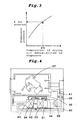
- a pressure (evaporation temperature) of the evaporator 34 can be calculated from a value detected by the temperature sensor 42. This is because the pressure in the evaporator 34 and the temperature of the drying air dehumidified by the evaporator 34 have a correlation as shown in Fig. 3 , and if one of them is detected, the other one is uniquely determined. Further, if the open/close valve 41 is used, it is possible to adjust the flow rate of drying air flowing into the bypass circuit in accordance with the calculated pressure value of the evaporator 34.
- the enthalpy of air around the inlet of the evaporator 34 can be controlled, and the pressure in the evaporator 34 can be controlled. Therefore, if the opening of the open/close valve 41 is adjusted and the pressure in the evaporator 34 is optimally controlled from the actuation to the completion of the drying operation of the heat pump type drying apparatus, it is possible to prevent the pressure in the evaporator from being reduced, the drying time can be shortened and thus, energy conservation can be realized.
- the open/close valve 43 is fully opened, and the flow rate of air in the bypass circuit 38 is maximized.
- the input to the compressor 31 can be increased, and the rising speed of the temperature of air in the duct can be increased.
- the opening of the open/close valve 41 is adjusted, and the pressure in the evaporator 34 is controlled to the optimal pressure.
- the performance of the compressor 31 is enhanced (performance enhancing factor) due to a reduction of the compression ratio (ratio of the discharging pressure and the sucking pressure of the compressor 31).
- the dehumidifying ability of the evaporator 34 is deteriorated (performance deteriorating factor). That is, the optimal value which depends on the compressor performance characteristics and the dehumidification ability characteristics exists in the pressure of the evaporator 34.
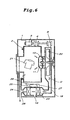
- Fig. 4 is a block diagram of a heat pump type drying apparatus according to a third embodiment of the invention.
- a heat pump apparatus is constituted by connecting the compressor 31, the radiator 32, the expansion valve 33 and the evaporator 34 to one another through pipes 36, and by charging the refrigerant thereinto.
- the refrigerant a refrigerant which can be brought into a supercritical state on the radiating side, such as a CO 2 refrigerant for example, is charged.
- This embodiment has the bypass circuit 39 through which a portion of the drying air heated by the radiator 32 flows to an inlet of the evaporator 34 without coming into contact with the subject 37, a super heat detecting device (a for example, temperature sensor 43) for detecting the temperature of refrigerant around the inlet of the evaporator 34 and a temperature sensor 44 for detecting the temperature of refrigerant around the exit of the evaporator 34), and the open/close valve 41 capable of adjusting the flow rate of drying air which flows into the bypass circuit using a value detected by the super heat detecting device.
- a super heat detecting device a for example, temperature sensor 43
- a temperature sensor 44 for detecting the temperature of refrigerant around the exit of the evaporator 34
- the open/close valve 41 capable of adjusting the flow rate of drying air which flows into the bypass circuit using a value detected by the super heat detecting device.
- the flow rate of drying air flowing into the bypass circuit can be adjusted in accordance with the detected super heat value. That is, if an opening of the open/close valve 41 is adjusted, the enthalpy of air around the inlet of the evaporator 34 can be controlled, and the super heat value can be controlled. Therefore, if the opening of the open/close valve 41 is adjusted and the super heat value is optimally controlled from the actuation to the completion of the drying operation of the heat pump type drying apparatus, the liquid compression of the compressor can be avoided, the drying time can be shortened and thus, energy conservation can be realized.
- the super heat control method In the heat pump type drying apparatus, optimal super heat exists in terms of efficiency and safety. The efficiency is most excellent when the super heat is zero (the state of the evaporator exit refrigerant is on a saturated vapor line), but in order to prevent the liquid compression of the compressor, a margin of safety is taken into account, the super heat of about 10 degrees is set to the optimal value in many cases. However, in the heat pump type drying apparatus, since the temperature condition of drying air is varied from the actuation to the completion of the drying operation, the super heat is also varied. With the variation of the super heat, the efficiency of the heat pump is deteriorated, and a danger of the compressor 31 operating to compress liquid exists.
- the opening of the open/close valve 41 is varied in accordance with a detected super heat value, and the flow rate of drying air flowing into the bypass circuit 39 is varied.
- the super heat value can be converged on the target value.
- the same effects can also be obtained even if a pressure sensor for detecting the sucking pressure of the compressor 31 and a temperature sensor for detecting the temperature of the exit of the evaporator 34 are provided.
- Fig. 5 is a block diagram of a heat pump type drying apparatus according to a fourth embodiment of the invention.
- a heat pump apparatus is constituted by connecting the compressor 31, the radiator 32, the expansion valve 33 and the evaporator 34 to one another through pipes 36, and by charging the refrigerant thereinto.
- the refrigerant a refrigerant which can be brought into a supercritical state on the radiating side, such as a CO 2 refrigerant for example, is charged.
- the bypass circuit 39 is provided therein with an air-refrigerant heat exchanger 45 (for example, a fin tube type heat exchanger) through which drying air flowing through the bypass circuit 39 heat-exchanges with a portion of the pipe between the compressor 31 and the evaporator 34.
- an air-refrigerant heat exchanger 45 for example, a fin tube type heat exchanger
- the refrigerant heats the drying air in the air-refrigerant heat exchanger 45 in addition to the evaporator 34, and the same effects as that of the increase of a transfer area of the evaporator 34 can be obtained.
- the super heat is increased, and the pressure rising effect of the evaporator 34 is enhanced. Therefore, it is possible to increase the temperature range and the air quantity region in which the heat pump type drying apparatus can be operated.
- the open/close valve 41 is added to this embodiment, the flow rate of drying air flowing into the bypass circuit is adjusted, and the heat pump type drying apparatus is operated optimally, the energy-conservation effect can be obtained in addition to the above-described effects.
- the heat pump type drying apparatus of the present invention has a bypass circuit through which a portion of drying air heated by a radiator flows to an inlet of an evaporator without coming into contact with a subject.
- the apparatus is effective for drying clothes, a bathroom, or any other item which needs to be dried or dehumidified.
- the apparatus can also be used for drying plateware, garbage and the like.
Landscapes
- Engineering & Computer Science (AREA)
- Textile Engineering (AREA)
- Mechanical Engineering (AREA)
- General Engineering & Computer Science (AREA)
- Drying Of Solid Materials (AREA)
- Detail Structures Of Washing Machines And Dryers (AREA)
Abstract
Claims (9)
- Appareil de séchage pour sécher un sujet, dans lequel un réfrigérant circule à travers un compresseur, un radiateur, un mécanisme d'expansion et un évaporateur par le biais de tuyaux, ledit appareil de séchage comprenant : une trajectoire d'écoulement d'air de séchage pouvant fonctionner pour introduire l'air de séchage chauffé par le radiateur dans le sujet à sécher, déshumidifier l'air de séchage qui a été introduit dans le sujet en utilisant l'évaporateur et chauffer l'air de séch age déshumidifié pour le ramener à l'état d'air de séchage ; et un circuit de dérivation à travers lequel une partie de l'air de séchage chauffé par le radiateur s'écoule dans l'évaporateur sans entrer en contact avec le sujet à sécher,
dans lequel l'appareil de séchage comprend en outre un dispositif de détection de débit de circuit de dérivation pouvant fonctionner pour détecter un débit de l'air de séchage qui s'écoule dans ledit circuit de dérivation ;
et un dispositif de réglage de débit d'air de dérivation pouvant fonctionner pour régler le débit de l'air de séchage qui s'écoule dans ledit circuit de dérivation en utilisant une valeur détectée par ledit dispositif de détection de débit de circuit de dérivation. - Appareil de séchage selon la revendication 1, comprenant en outre un dispositif de détection de surchauffe pouvant fonctionner pour détecter la surchauffe, qui est une différence entre une température d'aspiration de réfrigérant du compresseur et une température d'évaporation de réfrigérant de l'évaporateur ; et un dispositif de réglage de débit d'air de dérivation pouvant fonctionner pour régler un débit d'air de séchage qui s'écoule dans ledit circuit de dérivation en utilisant une valeur détectée par ledit dispositif de détection de surchauffe.
- Appareil de séchage selon la revendication 1, dans lequel l'air de séchage qui s'écoule à travers ledit circuit de dérivation effectue un échange thermique avec une partie des tuyaux qui est positionnée entre le compresseur et l'évaporateur.
- Appareil de séchage selon la revendication 1, comprenant en outre un dispositif de détection de température pouvant fonctionner pour détecter une température de l'air de séchage déshumidifié par l'évaporateur ; et un dispositif de réglage de débit d'air de dérivation pouvant fonctionner pour régler un débit de l'air de séchage qui s'écoule dans ledit circuit de dérivation en utilisant une valeur détectée par ledit dispositif de détection de température.
- Appareil de séchage selon la revendication 1, dans lequel par rapport à un point auquel l'air de séchage qui passe à travers ledit circuit de dérivation rencontre l'air de séchage qui passe à travers le sujet à sécher, l'air de séchage qui passe à travers ledit circuit de dérivation atteint le point de rencontre à partir d'une position située au-dessous du point de rencontre dans une direction de gravité de l'air de séchage qui passe à travers le sujet à sécher.
- Appareil de séchage selon la revendication 1, dans lequel ladite trajectoire d'écoulement l'air de séchage est prévue avec un récipient de réception de réfrigérant pouvant fonctionner pour recevoir un réfrigérant.
- Appareil de séchage selon la revendication 6, dans lequel ledit récipient de réception de réfrigérant est disposé dans ladite trajectoire d'écoulement d'air de séchage à un emplacement situé entre une partie en aval du radiateur et une partie en amont de l'évaporateur.
- Appareil de séchage selon la revendication 1, dans lequel le compresseur, le radiateur et le mécanisme d'expansion sont actionnés dans un état dans lequel leur côté de haute pression est dans un état supercritique.
- Procédé de séchage pour sécher un sujet situé à l'intérieur d'un circuit, ledit procédé de séchage comprenant les étapes consistant à : déshumidifier et chauffer l'air pour obtenir un air de séchage ayant une température élevée et une faible humidité ; faire passer une partie de l'air de séchage à travers le circuit pour amener la partie de l'air de séchage en contact avec le sujet ;
faire passer une autre partie de l'air de séchage à travers un circuit de dérivation, le circuit de dérivation étant agencé pour éviter qu'une autre partie de l'air de séchage vienne en contact avec le sujet ; et mélanger la partie de l'air de séchage mise en contact avec le sujet et l'autre partie de l'air qui est passée à travers le circuit de dérivation pour obtenir l'air,
dans lequel le procédé de séchage comprend en outre l'étape consistant à régler un débit de l'air de séchage qui passe à travers le circuit de dérivation, et
dans lequel le procédé de séchage comprend en outre les étapes consistant à détecter une température de l'air après qu'il a été déshumidifié et contrôler ledit réglage du débit de l'air de séchage qui est passé à travers le circuit de dérivation en utilisant la température détectée.
Applications Claiming Priority (2)
| Application Number | Priority Date | Filing Date | Title |
|---|---|---|---|
| JP2003333221 | 2003-09-25 | ||
| PCT/JP2004/014417 WO2005031231A1 (fr) | 2003-09-25 | 2004-09-24 | Appareil de sechage de type pompe a chaleur, appareil de sechage et procede de sechage |
Publications (2)
| Publication Number | Publication Date |
|---|---|
| EP1664647A1 EP1664647A1 (fr) | 2006-06-07 |
| EP1664647B1 true EP1664647B1 (fr) | 2011-06-08 |
Family
ID=34385984
Family Applications (1)
| Application Number | Title | Priority Date | Filing Date |
|---|---|---|---|
| EP04773505A Expired - Lifetime EP1664647B1 (fr) | 2003-09-25 | 2004-09-24 | Appareil de sechage de type pompe a chaleur, appareil de sechage et procede de sechage |
Country Status (5)
| Country | Link |
|---|---|
| US (1) | US7469486B2 (fr) |
| EP (1) | EP1664647B1 (fr) |
| JP (1) | JP4629670B2 (fr) |
| CN (1) | CN100453942C (fr) |
| WO (1) | WO2005031231A1 (fr) |
Cited By (1)
| Publication number | Priority date | Publication date | Assignee | Title |
|---|---|---|---|---|
| EP2586907A1 (fr) | 2011-10-31 | 2013-05-01 | Electrolux Home Products Corporation N.V. | Sèche-linge avec système de pompe à chaleur et recirculation d'air |
Families Citing this family (44)
| Publication number | Priority date | Publication date | Assignee | Title |
|---|---|---|---|---|
| KR100556503B1 (ko) * | 2002-11-26 | 2006-03-03 | 엘지전자 주식회사 | 건조기의 건조 시간제어 방법 |
| JP3696224B2 (ja) * | 2003-03-19 | 2005-09-14 | 株式会社グリーンセイジュ | 乾燥システム |
| JP2007533940A (ja) * | 2003-07-30 | 2007-11-22 | ベーエスハー ボッシュ ウント ジーメンス ハウスゲレーテ ゲゼルシャフト ミット ベシュレンクテル ハフツング | 少なくとも1つの部分プログラム段階「乾燥」を有する装置を運転する方法 |
| DE102004025528B4 (de) * | 2004-05-25 | 2010-03-04 | Eisenmann Anlagenbau Gmbh & Co. Kg | Verfahren und Vorrichtung zum Trocknen von beschichteten Gegenständen |
| JP4326445B2 (ja) * | 2004-10-20 | 2009-09-09 | 三洋電機株式会社 | 洗濯乾燥機 |
| US8015726B2 (en) * | 2005-06-23 | 2011-09-13 | Whirlpool Corporation | Automatic clothes dryer |
| US7698911B2 (en) * | 2005-11-30 | 2010-04-20 | General Electric Company | Methods and systems for detecting dryness of clothes in an appliance |
| KR101265605B1 (ko) * | 2006-07-04 | 2013-05-22 | 엘지전자 주식회사 | 의류 처리 장치 |
| JP5095240B2 (ja) * | 2007-03-07 | 2012-12-12 | ハイアール グループ コーポレーション | 乾燥機 |
| KR100894471B1 (ko) * | 2007-08-06 | 2009-04-22 | 엘지전자 주식회사 | 의류 건조기 |
| DE102007052839A1 (de) * | 2007-11-06 | 2009-05-07 | BSH Bosch und Siemens Hausgeräte GmbH | Trockner mit Wärmepumpenkreis |
| CN101487662B (zh) * | 2008-01-16 | 2012-01-04 | 凌建军 | 废热循环利用型高效节能烘干机 |
| JP2010104579A (ja) * | 2008-10-30 | 2010-05-13 | Toshiba Corp | 洗濯機 |
| KR101542389B1 (ko) * | 2009-02-05 | 2015-08-06 | 엘지전자 주식회사 | 히트펌프모듈 및 히트펌프모듈을 이용한 건조장치 |
| US8490438B2 (en) * | 2009-02-05 | 2013-07-23 | Lg Electronics Inc. | Laundry treatment device |
| WO2010095832A1 (fr) * | 2009-02-23 | 2010-08-26 | Lg Electronics Inc. | Lave-linge / sèche-linge |
| CN102292490B (zh) * | 2009-02-23 | 2013-09-25 | Lg电子株式会社 | 洗衣机 |
| KR101603106B1 (ko) * | 2009-03-03 | 2016-03-14 | 엘지전자 주식회사 | 세탁 장치 |
| WO2011067747A1 (fr) * | 2009-12-01 | 2011-06-09 | Budhi Haryanto | Climatisation multifonction économe en énergie et écologique en tant que sécheur et générateur d'eau potable de condensation et d'eau chaude |
| US20110199447A1 (en) * | 2010-02-17 | 2011-08-18 | Kabushiki Kaisha Toshiba | Image forming apparatus and drying method used in image forming apparatus |
| TR201006967A2 (tr) * | 2010-08-20 | 2011-06-21 | Vestel Beyaz Eşya Sanayi̇ Ve Ti̇caret Anoni̇m Şi̇rketi̇@ | Kurutma işlevi içeren bir ev gereci. |
| EP2468944B1 (fr) * | 2010-12-27 | 2019-02-20 | Electrolux Home Products Corporation N.V. | Séchoir à linge avec pompe de chaleur pour usage domestique |
| EP2527521A1 (fr) * | 2011-05-26 | 2012-11-28 | Electrolux Home Products Corporation N.V. | Sèche-linge à pompe à chaleur |
| EP2527522B1 (fr) * | 2011-05-26 | 2013-12-25 | Electrolux Home Products Corporation N.V. | Sèche-linge à pompe à chaleur |
| US9140396B2 (en) * | 2013-03-15 | 2015-09-22 | Water-Gen Ltd. | Dehumidification apparatus |
| US10174997B2 (en) * | 2013-04-26 | 2019-01-08 | David R Loebach | Crop drying system |
| CN104631069A (zh) * | 2013-11-07 | 2015-05-20 | 杭州三花研究院有限公司 | 干衣机及其控制方法 |
| CN104677065B (zh) * | 2014-10-15 | 2018-05-08 | 广西大革农业科技有限公司 | 一种全自动空气能烘茧机 |
| KR20180014615A (ko) | 2016-08-01 | 2018-02-09 | 엘지전자 주식회사 | 의류처리장치 |
| CN107062884A (zh) * | 2017-04-28 | 2017-08-18 | 浙江慧升热能科技有限公司 | 一种热泵烘干除湿一体机 |
| KR102408516B1 (ko) * | 2017-11-20 | 2022-06-13 | 엘지전자 주식회사 | 건조기의 제어방법 |
| EP3717688B1 (fr) * | 2017-11-28 | 2025-06-11 | Electrolux Professional AB (publ) | Sèche-linge à culbutage |
| CN110453468B (zh) * | 2018-05-08 | 2022-01-04 | 青岛海尔洗涤电器有限公司 | 一种衣物处理装置及控制方法 |
| KR102103943B1 (ko) * | 2018-09-28 | 2020-04-23 | 주식회사 포스코건설 | 배가스의 수분제거장치 및 이를 이용한 배가스의 재활용 방법 |
| CN109506424A (zh) * | 2018-10-29 | 2019-03-22 | 东莞市蓝冠环保节能科技有限公司 | 一种农产品的烘干方法 |
| CN109915893B (zh) * | 2019-04-02 | 2021-02-02 | 嘉兴市英伦电器科技有限公司 | 一种具有内部除湿功能的浴霸 |
| US11421375B2 (en) | 2020-02-24 | 2022-08-23 | Haier Us Appliance Solutions, Inc. | Detecting degree of dryness in a heat pump laundry appliance |
| US11913460B2 (en) | 2020-03-20 | 2024-02-27 | Greenheck Fan Corporation | Exhaust fan |
| EP3895594B1 (fr) * | 2020-04-17 | 2023-11-08 | BSH Hausgeräte GmbH | Appareil ménager comportant une pompe à chaleur et procédé de fonctionnement d'un tel appareil ménager |
| CN112923676B (zh) * | 2021-02-07 | 2022-10-18 | 长江师范学院 | 热泵烘干机组 |
| CN114264125A (zh) * | 2021-12-23 | 2022-04-01 | 玉溪新天力农业装备制造有限公司 | 一种具有余热回收功能的农业用烘干房 |
| DE102022204025A1 (de) * | 2022-04-26 | 2023-10-26 | BSH Hausgeräte GmbH | Verfahren zur Ermittlung der Endrestfeuchte in einem Wärmepumpentrockner sowie hierfür geeigneter Wärmepumpentrockner |
| CN114992992A (zh) * | 2022-06-21 | 2022-09-02 | 重庆科技学院 | 一种节能型的空气能热泵烘干房 |
| CN116592617A (zh) * | 2023-05-26 | 2023-08-15 | 广州奕至家居科技有限公司 | 一种压缩机的循环散热装置、散热方法及烘干机 |
Family Cites Families (10)
| Publication number | Priority date | Publication date | Assignee | Title |
|---|---|---|---|---|
| GB378384A (en) * | 1931-05-01 | 1932-08-02 | Alec Edward Sherman | Improved method of and apparatus for drying materials |
| GB1133098A (en) * | 1964-11-20 | 1968-11-06 | John Edward Randell | Improvements in and relating to drying apparatus |
| US5113882A (en) * | 1990-08-28 | 1992-05-19 | Electrovert Ltd. | Method of cleaning workpieces with a potentially flammable or explosive liquid and drying in the tunnel |
| DE4409607C2 (de) * | 1993-04-21 | 2002-03-14 | Miele & Cie | Kondensationswäschetrockner mit einer Wärmepumpe |
| US6035551A (en) * | 1993-09-24 | 2000-03-14 | Optimum Air Corporation | Automated air filtration and drying system for waterborne paint and industrial coatings |
| JP3321945B2 (ja) | 1993-12-24 | 2002-09-09 | 松下電器産業株式会社 | 衣類乾燥機 |
| JP2001116290A (ja) * | 1999-10-14 | 2001-04-27 | Toto Ltd | 暖房乾燥機 |
| JP2001198396A (ja) | 2000-01-24 | 2001-07-24 | Hitachi Ltd | 衣類乾燥機 |
| US6434857B1 (en) * | 2000-07-05 | 2002-08-20 | Smartclean Jv | Combination closed-circuit washer and drier |
| JP3600163B2 (ja) * | 2001-02-13 | 2004-12-08 | 三洋電機株式会社 | 車載空気調和機 |
-
2004
- 2004-09-24 EP EP04773505A patent/EP1664647B1/fr not_active Expired - Lifetime
- 2004-09-24 WO PCT/JP2004/014417 patent/WO2005031231A1/fr not_active Ceased
- 2004-09-24 US US10/549,579 patent/US7469486B2/en not_active Expired - Fee Related
- 2004-09-24 CN CNB2004800066751A patent/CN100453942C/zh not_active Expired - Fee Related
- 2004-09-24 JP JP2006519284A patent/JP4629670B2/ja not_active Expired - Fee Related
Cited By (2)
| Publication number | Priority date | Publication date | Assignee | Title |
|---|---|---|---|---|
| EP2586907A1 (fr) | 2011-10-31 | 2013-05-01 | Electrolux Home Products Corporation N.V. | Sèche-linge avec système de pompe à chaleur et recirculation d'air |
| WO2013064236A1 (fr) | 2011-10-31 | 2013-05-10 | Electrolux Home Products Corporation N.V. | Sèche-linge avec système de pompe à chaleur et recirculation d'air |
Also Published As
| Publication number | Publication date |
|---|---|
| US20060179681A1 (en) | 2006-08-17 |
| JP4629670B2 (ja) | 2011-02-09 |
| JP2007528975A (ja) | 2007-10-18 |
| US7469486B2 (en) | 2008-12-30 |
| CN100453942C (zh) | 2009-01-21 |
| EP1664647A1 (fr) | 2006-06-07 |
| WO2005031231A1 (fr) | 2005-04-07 |
| CN1759288A (zh) | 2006-04-12 |
Similar Documents
| Publication | Publication Date | Title |
|---|---|---|
| EP1664647B1 (fr) | Appareil de sechage de type pompe a chaleur, appareil de sechage et procede de sechage | |
| US7191543B2 (en) | Drying device and method of operation therefor | |
| CN110274443B (zh) | 热泵烘干系统及热泵烘干机组 | |
| EP3031976B1 (fr) | Appareil de traitement de vêtements avec système de pompe à chaleur | |
| US7975502B2 (en) | Heat pump apparatus and operating method thereof | |
| KR101632013B1 (ko) | 히트펌프 사이클을 구비한 응축식 의류 건조기 및 이의 제어방법 | |
| US9803313B2 (en) | Clothes treating apparatus | |
| JP5049495B2 (ja) | 木材の人工乾燥方法及びシステム | |
| CN101939479B (zh) | 包括热泵和加热器的滚筒干衣机及其操作方法 | |
| JP2004236965A (ja) | 衣類乾燥装置 | |
| KR101718041B1 (ko) | 의류건조기 및 이의 제어방법 | |
| JP2004239549A (ja) | 衣類乾燥装置 | |
| EP3256635B1 (fr) | Sèche-linge et procédé de fonctionnement d'un sèche-linge | |
| JP2007082586A (ja) | 衣類乾燥装置 | |
| JP2005279257A (ja) | 乾燥装置及びその運転方法 | |
| JP2004313765A (ja) | 乾燥装置及びその運転方法 | |
| JP2004020086A (ja) | 除湿乾燥空調装置 | |
| JP4528635B2 (ja) | 乾燥装置 | |
| JP2006204548A (ja) | 乾燥装置 | |
| KR100493871B1 (ko) | 제습 및 건조설비 | |
| JP2005265402A5 (fr) | ||
| CN120232258A (zh) | 烘干设备 | |
| FI104743B (fi) | Kuivauslaite tekstiilejä varten | |
| JP2006071139A (ja) | 乾燥装置及びその運転方法 | |
| JP2003185292A (ja) | 冷凍回路及びこれを使用した空調装置 |
Legal Events
| Date | Code | Title | Description |
|---|---|---|---|
| PUAI | Public reference made under article 153(3) epc to a published international application that has entered the european phase |
Free format text: ORIGINAL CODE: 0009012 |
|
| 17P | Request for examination filed |
Effective date: 20050922 |
|
| AK | Designated contracting states |
Kind code of ref document: A1 Designated state(s): DE FR GB |
|
| RIN1 | Information on inventor provided before grant (corrected) |
Inventor name: TAMURA, TOMOICHIRO Inventor name: YAKUMARU, YUUICHI Inventor name: NISHIWAKI, FUMITOSHI |
|
| DAX | Request for extension of the european patent (deleted) | ||
| RBV | Designated contracting states (corrected) |
Designated state(s): DE FR GB |
|
| RAP1 | Party data changed (applicant data changed or rights of an application transferred) |
Owner name: PANASONIC CORPORATION |
|
| 17Q | First examination report despatched |
Effective date: 20100708 |
|
| GRAP | Despatch of communication of intention to grant a patent |
Free format text: ORIGINAL CODE: EPIDOSNIGR1 |
|
| GRAS | Grant fee paid |
Free format text: ORIGINAL CODE: EPIDOSNIGR3 |
|
| GRAA | (expected) grant |
Free format text: ORIGINAL CODE: 0009210 |
|
| AK | Designated contracting states |
Kind code of ref document: B1 Designated state(s): DE FR GB |
|
| REG | Reference to a national code |
Ref country code: GB Ref legal event code: FG4D |
|
| REG | Reference to a national code |
Ref country code: DE Ref legal event code: R096 Ref document number: 602004032993 Country of ref document: DE Effective date: 20110721 |
|
| PLBE | No opposition filed within time limit |
Free format text: ORIGINAL CODE: 0009261 |
|
| STAA | Information on the status of an ep patent application or granted ep patent |
Free format text: STATUS: NO OPPOSITION FILED WITHIN TIME LIMIT |
|
| 26N | No opposition filed |
Effective date: 20120309 |
|
| GBPC | Gb: european patent ceased through non-payment of renewal fee |
Effective date: 20110924 |
|
| REG | Reference to a national code |
Ref country code: FR Ref legal event code: ST Effective date: 20120531 |
|
| REG | Reference to a national code |
Ref country code: DE Ref legal event code: R097 Ref document number: 602004032993 Country of ref document: DE Effective date: 20120309 |
|
| PG25 | Lapsed in a contracting state [announced via postgrant information from national office to epo] |
Ref country code: FR Free format text: LAPSE BECAUSE OF NON-PAYMENT OF DUE FEES Effective date: 20110930 Ref country code: GB Free format text: LAPSE BECAUSE OF NON-PAYMENT OF DUE FEES Effective date: 20110924 |
|
| PGFP | Annual fee paid to national office [announced via postgrant information from national office to epo] |
Ref country code: DE Payment date: 20180911 Year of fee payment: 15 |
|
| REG | Reference to a national code |
Ref country code: DE Ref legal event code: R119 Ref document number: 602004032993 Country of ref document: DE |
|
| PG25 | Lapsed in a contracting state [announced via postgrant information from national office to epo] |
Ref country code: DE Free format text: LAPSE BECAUSE OF NON-PAYMENT OF DUE FEES Effective date: 20200401 |