EP1665571B1 - Detektion eines prozesszustands-wechsels - Google Patents
Detektion eines prozesszustands-wechsels Download PDFInfo
- Publication number
- EP1665571B1 EP1665571B1 EP04764727A EP04764727A EP1665571B1 EP 1665571 B1 EP1665571 B1 EP 1665571B1 EP 04764727 A EP04764727 A EP 04764727A EP 04764727 A EP04764727 A EP 04764727A EP 1665571 B1 EP1665571 B1 EP 1665571B1
- Authority
- EP
- European Patent Office
- Prior art keywords
- measures
- carrier
- carrier frequency
- transmission quality
- quality
- Prior art date
- Legal status (The legal status is an assumption and is not a legal conclusion. Google has not performed a legal analysis and makes no representation as to the accuracy of the status listed.)
- Expired - Lifetime
Links
- 238000000034 method Methods 0.000 title claims abstract description 86
- 230000008569 process Effects 0.000 title claims abstract description 63
- 230000008859 change Effects 0.000 title claims abstract description 50
- 238000001514 detection method Methods 0.000 title abstract description 37
- 230000005540 biological transmission Effects 0.000 claims description 34
- 239000000969 carrier Substances 0.000 claims description 27
- 238000005309 stochastic process Methods 0.000 claims description 11
- 230000003044 adaptive effect Effects 0.000 claims description 4
- 238000005259 measurement Methods 0.000 claims 2
- 238000012935 Averaging Methods 0.000 description 14
- 238000004891 communication Methods 0.000 description 8
- 230000006870 function Effects 0.000 description 6
- 230000009471 action Effects 0.000 description 5
- 230000006399 behavior Effects 0.000 description 4
- 238000005516 engineering process Methods 0.000 description 4
- 238000010586 diagram Methods 0.000 description 3
- 230000001934 delay Effects 0.000 description 2
- 238000005315 distribution function Methods 0.000 description 2
- 238000012544 monitoring process Methods 0.000 description 2
- 230000003287 optical effect Effects 0.000 description 2
- 238000001228 spectrum Methods 0.000 description 2
- 230000001052 transient effect Effects 0.000 description 2
- 235000008694 Humulus lupulus Nutrition 0.000 description 1
- 238000012937 correction Methods 0.000 description 1
- 230000000694 effects Effects 0.000 description 1
- 230000001747 exhibiting effect Effects 0.000 description 1
- 230000007246 mechanism Effects 0.000 description 1
- 239000004753 textile Substances 0.000 description 1
Images
Classifications
-
- H—ELECTRICITY
- H04—ELECTRIC COMMUNICATION TECHNIQUE
- H04B—TRANSMISSION
- H04B1/00—Details of transmission systems, not covered by a single one of groups H04B3/00 - H04B13/00; Details of transmission systems not characterised by the medium used for transmission
- H04B1/06—Receivers
- H04B1/10—Means associated with receiver for limiting or suppressing noise or interference
-
- H—ELECTRICITY
- H04—ELECTRIC COMMUNICATION TECHNIQUE
- H04B—TRANSMISSION
- H04B1/00—Details of transmission systems, not covered by a single one of groups H04B3/00 - H04B13/00; Details of transmission systems not characterised by the medium used for transmission
- H04B1/69—Spread spectrum techniques
- H04B1/713—Spread spectrum techniques using frequency hopping
- H04B1/715—Interference-related aspects
-
- H—ELECTRICITY
- H04—ELECTRIC COMMUNICATION TECHNIQUE
- H04B—TRANSMISSION
- H04B1/00—Details of transmission systems, not covered by a single one of groups H04B3/00 - H04B13/00; Details of transmission systems not characterised by the medium used for transmission
- H04B1/69—Spread spectrum techniques
- H04B1/713—Spread spectrum techniques using frequency hopping
- H04B1/715—Interference-related aspects
- H04B2001/7154—Interference-related aspects with means for preventing interference
Definitions
- the present invention relates to detecting process state changes.
- Bluetooth ® wireless technology utilizes a form of spread spectrum communication techniques called "frequency hopping."
- frequency hopping a communication device is allocated a bandwidth of the radio frequency spectrum that is wider than that which is actually necessary to communicate the information.
- the allocated bandwidth is divided up into a set of adjacent carrier frequencies, known to users of the communication system.
- a transmitter selects one of the carrier frequencies, and begins transmitting.
- the transmitter rapidly switches its selection from one carrier to another, the effect of which is that the transmitter constantly "hops" from one carrier to another during the transmission.
- the transmitter usually relies on a predetermined pseudo-random hop sequence.
- Frequency hopping offers a number of advantages over transmission techniques that utilize the same carrier frequency continuously, including the fact that frequency hopping transmission adds very little noise to the overall allocated frequency band, thereby enabling many other wireless devices to operate within the same allocated frequency band at the same time.
- Frequency hopping also offers advantages in reception, including resistance to frequency selective noise/interference.
- a simple way of looking at this is by considering a noise source on one or a few of the set of carrier frequencies; even if the transmitter happens to transmit on one of these "noisy" carrier frequencies, this transmission is only momentary. The transmission is likely to soon hop to a carrier frequency that is not subject to the frequency selective noise. Since most modem communication systems also employ error detection and correction mechanisms in the way the information is encoded, the receiver can usually detect and often correct any received erroneous information.
- Adaptive Frequency Hopping has recently been released by the Bluetooth® Special Interest Group in a draft specification. Using this technique, the Bluetooth® radio can select a number of carrier frequencies that will be skipped during frequency hopping, thereby making them unused for radio communications.
- An example of an AFH scheme has been described in U.S. patent application 09/418,562 filed on October 15, 1999 by J.C. Haartsen and published as WO01/29984 .
- determining whether a given carrier frequency should be skipped during frequency hopping involves detecting whether some measure of quality for a given carrier has changed from an acceptable value to an unacceptable value.
- a measure of quality may, for example, be a measured packet error rate associated with a carrier or a set of neighboring carriers.
- Another example of a measure of quality is the rate of received interference power samples for a carrier or a set of neighboring carriers.
- the measure of quality can be considered the output of a discrete time, binary random process that indicates the observed packet transmission successes or failures on the considered carrier or carrier set.
- a significant change in the measure of quality e.g., packet error rate
- this carrier or carrier set should be excluded from the set of used carriers.
- Measures of quality are determined by monitoring the carrier or carrier set over some period of time. It is desirable, for example, to very quickly detect severe increases in packet error rate (i.e., sudden changes from a low value to a very high value), because failure to do so will noticeably degrade the communication link performance. However, it is also important to be able to reliably detect smaller changes in the measure of quality (e.g., packet error rate); a larger detection delay is permissible for these instances.
- Detecting the process state change involves determining whether the short time average ofx has increased from an initial value X 1 to some larger value X 2 . This determination should be made after a reasonably short delay, and yet should be characterized by a low false alarm probability as well as a low detection failure probability.
- the false alarm probability is the probability that the detection process will conclude from its observations of x that X has increased to X 2 , although X in fact has not.
- the detection failure probability is the probability that the detection process will conclude from its observations of x that X still has the value X 1 , although in fact X has increased to X 2 .
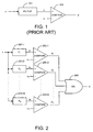
- FIG. 1 is a block diagram illustrating a conventional process state change detector.
- Such process state change detectors usually employ a filter 101 that generates y , a (typically unbiased) estimate of X , from the observed samples of the stochastic process x. This estimate, y, is supplied to a comparator 103 that compares y to a threshold value, u. If y ( t ) > u, then the comparator's output, denoted d , indicates a decision that X has increased to X 2 , otherwise the comparator's output, d , indicates that X remained equal to (or otherwise associated with) X 1 . Typically, X 1 ⁇ u ⁇ X 2 for an unbiased estimate y .
- T is the current time.
- the variance ofy must be smaller, the smaller the difference between X 1 and X 2 . This means in turn that a smaller difference between X 1 and X 2 requires a larger effective averaging window of the filter, which in turn increases the average detection delay of the process state change detector.
- the process state change detector is required to reliably detect changes to arbitrary values X 2 above a certain minimum X 2_min , but has to maintain low decision error probabilities p FA and p DF in all cases.
- designing for the limiting case means choosing the averaging window to be accordingly large, which in turn increases the decision delay even in cases in which the actual X 2 is well above X 2_min .
- US 5 727 856 shows a controller for vehicle control exhibiting low pass behaviour, which is variable depending on whether or not certain operating conditions are present.
- the variable low pass behaviour can be characterized by various time constants, and the parameter describing the operating conditions, e.g. a drive slip or a longitudinal velocity of the vehicle, can be evaluated by comparing it with a threshold.
- a similar system from the field of echo cancelling is known from US 6 035 033 , in which filter coefficients of correlators are monitored for changes by monitoring absolute values of auxiliary correlators in comparators.
- US 4 758 968 shows a method and an apparatus for measuring the variability of textile strands, in which a selected parameter is continuously monitored and the resulting signal is applied to each of a plurality of integrating networks, each having a different predetermined time constant.
- such detection includes, in each of a plurality of filters having differing time constants, generating an estimated average process state from observed samples of the process.
- a plurality of state change decisions are generated by comparing each of the plurality of estimated process states with a respective one of a plurality of threshold values. It is then decided that the process has changed state if any one or more of the state change decisions indicates that the process has changed state.
- the process is a stochastic process.
- the observed samples of the process are measures of quality for a given carrier or set of neighboring carriers in a telecommunications system.
- the measures of quality for the given carrier may be measures of packet error rate associated with the given carrier or set of neighboring carriers.
- the measures of quality for the given carrier may be measures of received interference power samples associated with the given carrier or set of neighboring carriers.
- a combination of measures packet error rate and measures of received interference may be used as the measures of quality.
- the various process state change detection methods and apparatuses described herein may be applied to determine whether a carrier frequency should be skipped in an adaptive frequency hopping telecommunications system.
- the transmission quality of the carrier frequency is measured over time. It is then determined whether the quality of the carrier frequency has changed from an acceptable level to an unacceptable level; and it is decided to skip the carrier frequency if the quality of the carrier frequency has changed from the acceptable level to the unacceptable level.
- the invention can additionally be considered to be embodied entirely within any form of computer readable carrier, such as solid-state memory, magnetic disk, optical disk or carrier wave (such as radio frequency, audio frequency or optical frequency carrier waves) containing an appropriate set of computer instructions that would cause a processor to carry out the techniques described herein.
- computer readable carrier such as solid-state memory, magnetic disk, optical disk or carrier wave (such as radio frequency, audio frequency or optical frequency carrier waves) containing an appropriate set of computer instructions that would cause a processor to carry out the techniques described herein.
- any such form of embodiments may be referred to herein as "logic configured to" perform a described action, or alternatively as “logic that" performs a described action.
- detecting a process state change involves invoking a plurality of filters with differing time constants.
- the output from each of the filters is compared with a corresponding one of a plurality of threshold values. If any of these comparisons detects a change in state, then the output of the process state change detection also indicates a change in state; otherwise, no change in state is indicated.
- Such an arrangement provides both fast detection of severe changes of X, and also reliable detection of small changes of X (but at a correspondingly slower speed).
- the observed samples of the stochastic process x are supplied to each of a number, N, of filters 201-1 ... 201-N.
- Each filter 201-n (where 1 ⁇ n ⁇ N) generates an output, y n , which is a (typically unbiased) estimate of X , from the observed samples of the stochastic process x .
- Each of the estimates, y 1 ... y N is supplied to a corresponding one of N comparators 203 that compares each value y n to a corresponding threshold value, u n .
- y n ( t )>u n the comparator's output, denoted d n , indicates a decision that X has increased to X 2 , otherwise the comparator's output, d n , indicates that X remained equal to (or otherwise associated with) X 1 .
- Each of the decisions, d 1 ... d N is supplied to a corresponding one of N inputs of a logical OR function 205, whose output d is asserted if and only if at least one of the inputs d 1 ...d N is asserted.
- the output, d , of the logical OR function 205 represents the final decision of the exemplary process state change detector.
- each of the filters 201-1...201-N preferably has a different time constant. And, as indicated above, a change of X from X 1 to X 2 >X 2_min is decided if any of the comparators 203-1 ... 203-N detects a change. Assume that a first filter 201-1 is the filter having the largest averaging window, that an N -th filter 201-N is the filter having the smallest averaging window, and that the remaining filters 201-2 ... 201-N-1 have various averaging windows whose sizes are in between the largest and smallest. For each of the filters 201-1 ... 201-N, the corresponding threshold values u 1 ...
- u N are set to a level that will result in a low and/or otherwise acceptable false alarm probability p FA .
- the N -th threshold value, u N should be set to a level that is large enough to cause the resultant false alarm probability p FA to be low even though the variance of y N is large (due to the small averaging window size). That is, using a larger threshold value u N (compared to the other threshold values u 1 ... u N-1 ) compensates for the larger variance of y N (compared to the variance of the other estimates y 1 ... y N-1 ), so that the last comparator 203-N maintains a low false alarm probability p FA .
- the relatively large value of u N coupled with the relatively small averaging window of the N -th filter 201-N means that severe increases of X will be very quickly detected and indicated in the decision d N without sacrificing a low detection failure probability despite the existence of small increases of X.
- the filters 201-2 ... 201-N-1 having averaging windows in between these two extremes, in conjunction with corresponding threshold values u 2 ... u N- 1 are used to detect moderate increases of X to values X 2 >X 2min .
- the detection delays associated with these various filter paths have a corresponding range in between the longest delay (associated with the first filter 201-1) and the shortest delay (associated with the N -th filter 201-N).
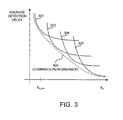
- FIG. 3 is a set of graphs 301, 303, 305, 307 showing, for each of the four filters F 1 ... F 4 , the filter's average detection delay as a function of the short time average X 2 of a stochastic process after the increase.
- detecting a change in the short time average X 2 is equivalent to detecting a shift in the distribution function (i.e., detecting that the observed samples are now clustered around a different value). Consequently, for each of the four filters, F 1 ... F 4 , detection occurs more rapidly for larger changes in X 2 than for small changes; this characteristic is illustrated by each of the four graphs 301, 303, 305, and 307.
- the average detection delays of the four filters F 1 ... F 4 are not equal to one another because of their different averaging window lengths. Rather, it can be seen from the four graphs 301, 303, 305, 307 that for sufficiently large values of X 2 , the fourth filter F 4 will exhibit the shortest average detection delay; that for a range of just lower values, the third filter F 3 will exhibit the shortest average detection delay, and so on until detection of the lowest values of X 2 can be performed most quickly by the first filter F 1 .
- This overall performance can be accomplished by setting the four threshold values u 1 ... u 4 to suitable values that will achieve a desired false alarm probabilities, p FA , for the entire detector. These values are therefore based on averaging window size of each of the filters F n .
- the curve 309 (illustrated by the dotted line) illustrates an approximation of the overall performance that can be achieved by settings of this nature.
- the following guidance is offered with respect to how to select the number of filters, and/or how to decide the sizes of the averaging windows of all of the filters.
- averaging window sizes For different filter parameters (e.g., averaging window sizes), determine the optimal threshold value u and the performance of a conventional change detector.
- the performance results for the investigated filter parameter settings are drawn in a figure, similar to FIG. 3 .
- the detection performance requirements for the complete detector like X 2_min and the maximum detection delay for large X 2 limit the relevant area in the figure, and indicate how many different filters are needed, and which parameters they should have. For example, in FIG.
- the curves 301, 303, 305, and 307 of the individual filters are sufficiently different in the sense that they cover sufficiently different regions of the area in the figure.
- a certain filter can be removed from the combined change detector if its contribution to the overall covered area in a figure (like FIG. 3 ) is not relevant.
- another filter should be added if the given set does not provide sufficient coverage for a desired coverage area.
- the exemplary embodiment depicted in FIG. 2 employs a logical OR function to determine whether any of the decisions d 1 ... d N is being asserted.
- any equivalent logic could be substituted therefor including, but limited to, the use of negative logic arrangements (e.g., including NOR or NAND arrangements) or logic that determines whether the number of decisions d 1 ... d N presently being asserted is greater than or equal to one.
- the observed samples of the process upon which a state change detection is based are measures of quality for a given carrier or set of neighboring carriers in a telecommunications system.
- the measures of quality for the given carrier may be measures of packet error rate associated with the given carrier and/or set of neighboring carriers.
- the measures of quality for the given carrier are measures of received interference power samples associated with the given carrier and/or set of neighboring carriers.
- the measures of quality for the given carrier are formed from a combination of measures of packet error rate associated with the given carrier and/or set of neighboring carriers and measures of received interference power samples associated with the given carrier or set of neighboring carriers.
Landscapes
- Engineering & Computer Science (AREA)
- Computer Networks & Wireless Communication (AREA)
- Signal Processing (AREA)
- Mobile Radio Communication Systems (AREA)
- Monitoring And Testing Of Transmission In General (AREA)
- Testing Or Calibration Of Command Recording Devices (AREA)
- Radar Systems Or Details Thereof (AREA)
- Testing And Monitoring For Control Systems (AREA)
Claims (27)
- Verfahren zum Erfassen einer Zustandsänderung in einem Prozess, wobei das Verfahren folgende Schritte aufweist:• Erzeugen, in jedem einer Mehrzahl von Filtern (201-1, 201-2, 201-N) mit unterschiedlichen Zeitkonstanten, eines geschätzten durchschnittlichen Prozesszustands aus beobachteten Proben des Prozesses;• Erzeugen einer Mehrzahl von Zustandsänderungsentscheidungen durch Vergleichen jedes der Mehrzahl von geschätzten Prozesszuständen mit einem jeweiligen einer Mehrzahl von Schwellenwerten (u1, u2, uN), wobei jeder der Mehrzahl von Schwellenwerten umgekehrt relatiert zu der jeweiligen der Zeitkonstanten ist; und• Entscheiden, dass der Prozess einen Zustand geändert hat, wenn eine oder mehrere der Zustandsänderungsentscheidungen anzeigen, dass der Prozess einen Zustand geändert hat.
- Verfahren nach Anspruch 1, bei dem der Prozess ein stochastischer Prozess ist.
- Verfahren nach Anspruch 1, bei dem die beobachteten Proben des Prozesses Maße einer Qualität für einen gegebenen Träger oder Satz von benachbarten Trägern bei einem Telekommunikationssystem sind.
- Verfahren nach Anspruch 3, bei dem die Maße einer Qualität für den gegebenen Träger Maße einer Paketfehlerrate sind, die dem gegebenen Träger oder Satz von benachbarten Trägern zugeordnet ist.
- Verfahren nach Anspruch 3, bei dem die Maße einer Qualität für den gegebenen Träger Maße von Proben einer empfangenen Störungsleistung sind, die dem gegebenen Träger oder Satz von benachbarten Trägern zugeordnet sind.
- Verfahren nach Anspruch 3, bei dem die Maße einer Qualität für den gegebenen Träger aus einer Kombination von Maßen einer Paketfehlerrate, die dem gegebenen Träger oder Satz von benachbarten Trägern zugeordnet ist, und Maßen von Proben einer empfangenen Störungsleistung, die dem gegebenen Träger oder Satz von benachbarten Trägern zugeordnet sind, gebildet sind.
- Verfahren zum Bestimmen, ob eine Trägerfrequenz bei einem adaptiven Frequenzsprung-Telekommunikationssystem übersprungen werden sollte, wobei das Verfahren folgende Schritte aufweist:• Messen einer Übertragungsqualität der Trägerfrequenz über die Zeit;• Bestimmen, ob sich die Übertragungsqualität der Trägerfrequenz von einem akzeptablen Niveau zu einem inakzeptablen Niveau geändert hat; und• Entscheiden, die Trägerfrequenz zu überspringen, wenn sich die Übertragungsqualität der Trägerfrequenz von dem akzeptablen Niveau zu dem inakzeptablen Niveau geändert hat,• wobei das Bestimmen, ob sich die Übertragungsqualität der Trägerfrequenz von dem akzeptablen Niveau zu dem inakzeptablen Niveau geändert hat, folgende Schritte aufweist:o Erzeugen, in jedem einer Mehrzahl von Filtern (201-1, 201-2, 201-N) mit unterschiedlichen Zeitkonstanten, eines geschätzten durchschnittlichen Maßes einer-Qualität aus den Messungen einer Übertragungsqualität der Trägerfrequenz;o Erzeugen einer Mehrzahl von Zustandsänderungsentscheidungen durch Vergleichen jedes der Mehrzahl von geschätzten durchschnittlichen Maßen einer Qualität mit einem jeweiligen einer Mehrzahl von Schwellenwerten (u1, u2, uN), wobei jeder der Mehrzahl von Schwellenwerten umgekehrt relatiert zu der jeweiligen der Zeitkonstanten ist; undo Entscheiden, dass sich die Übertragungsqualität der Trägerfrequenz von dem akzeptablen Niveau zu dem inakzeptablen Niveau geändert hat, wenn eine oder mehrere der Zustandsänderungsentscheidungen anzeigen, dass sich die Übertragungsqualität der Trägerfrequenz von dem akzeptablen Niveau zu dem inakzeptablen Niveau geändert hat.
- Verfahren nach Anspruch 7, bei dem die Maße einer Übertragungsqualität für die Trägerfrequenz Maße einer Paketfehlerrate sind, die der Trägerfrequenz zugeordnet ist.
- Verfahren nach Anspruch 7, bei dem die Maße einer Übertragungsqualität für die Trägerfrequenz Maße einer Paketfehlerrate sind, die der Trägerfrequenz und einem Satz von benachbarten Trägern zugeordnet ist.
- Verfahren nach Anspruch 7, bei dem die Maße einer Übertragungsqualität für die Trägerfrequenz Maße von Proben einer empfangenen Störungsleistung sind, die der Trägerfrequenz zugeordnet sind.
- Verfahren nach Anspruch 7, bei dem die Maße einer Übertragungsqualität für die Trägerfrequenz Maße von Proben einer empfangenen Störungsleistung sind, die der Trägerfrequenz und einem Satz von benachbarten Trägerfrequenzen zugeordnet sind.
- Verfahren nach Anspruch 7, bei dem die Maße einer Übertragungsqualität für den gegebenen Träger aus einer Kombination von Maßen einer Paketfehlerrate, die dem gegebenen Träger zugeordnet ist, und Maßen von Proben einer empfangenen Störungsleistung, die dem gegebenen Träger zugeordnet sind, gebildet sind.
- Verfahren nach Anspruch 7, bei dem die Maße einer Übertragungsqualität für den gegebenen Träger aus einer Kombination von Maßen einer Paketfehlerrate, die dem gegebenen Träger und einem Satz von benachbarten Trägern zugeordnet ist, und Maßen von Proben einer empfangenen Störungsleistung, die dem gegebenen Träger und einem Satz von benachbarten Trägern zugeordnet sind, gebildet sind.
- Prozesszustandsänderungsdetektor mit:• einer Mehrzahl von Filtern (201-1, 201-2, 201-N) mit unterschiedlichen Zeitkonstanten, wobei jedes der Filter betreibbar ist, um aus beobachteten Proben eines Prozesses einen geschätzten durchschnittlichen Prozesszustand zu erzeugen;• einer Vergleichslogik (203-1, 203-2, 203-N), die betreibbar ist, um durch Vergleichen jedes der Mehrzahl von geschätzten Prozesszuständen mit einem jeweiligen einer Mehrzahl von Schwellenwerten (u1, u2, uN), wobei jeder der Mehrzahl von Schwellenwerten umgekehrt relatiert zu der jeweiligen der Zeitkonstanten ist, eine Mehrzahl von Zustandsänderungsentscheidungen zu erzeugen; und● einer Endentscheidungslogik (205), die betreibbar ist, um zu entscheiden, dass der Prozess einen Zustand geändert hat, wenn eine oder mehrere der Zustandsänderungsentscheidungen anzeigen, dass der Prozess einen Zustand geändert hat.
- Prozesszustandsänderungsdetektor nach Anspruch 14, bei dem der Prozess ein stochastischer Prozess ist.
- Prozesszustandsänderungsdetektor nach Anspruch 14, bei dem die beobachteten Proben des Prozesses Maße einer Qualität für einen gegebenen Träger oder Satz von benachbarten Trägern bei einem Telekommunikationssystem sind.
- Prozesszustandsänderungsdetektor nach Anspruch 16, bei dem die Maße einer Qualität für den gegebenen Träger Maße einer Paketfehlerrate sind, die dem gegebenen Träger oder Satz von benachbarten Trägern zugeordnet ist.
- Prozesszustandsänderungsdetektor nach Anspruch 16, bei dem die Maße einer Qualität für den gegebenen Träger Maße von Proben einer empfangenen Störungsleistung sind, die dem gegebenen Träger oder Satz von benachbarten Trägern zugeordnet sind.
- Prozesszustandsänderungsdetektor nach Anspruch 16, bei dem die Maße einer Qualität für den gegebenen Träger aus einer Kombination von Maßen einer Paketfehlerrate, die dem gegebenen Träger oder Satz von benachbarten Trägern zugeordnet ist, und Maßen von Proben einer empfangenen Störungsleistung, die dem gegebenen Träger oder Satz von benachbarten Trägern zugeordnet sind, gebildet sind.
- Prozesszustandsänderungsdetektor nach Anspruch 14, bei dem die Endentscheidungslogik betreibbar ist, um eine logische ODER-Funktion durchzuführen.
- Vorrichtung, die betreibbar ist, um zu bestimmen, ob eine Trägerfrequenz bei einem adaptiven Frequenzsprung-Telekommunikationssystem übersprungen werden sollte, wobei die Vorrichtung folgende Merkmale aufweist:• eine Logik, die betreibbar ist, um eine Übertragungsqualität der Trägerfrequenz über die Zeit zu messen;• eine Logik, die betreibbar ist, um zu bestimmen, ob sich die Übertragungsqualität der Trägerfrequenz von einem akzeptablen Niveau zu einem inakzeptablen Niveau geändert hat; und● eine Logik, die betreibbar ist, um zu entscheiden, die Trägerfrequenz zu überspringen, wenn sich die Übertragungsqualität der Trägerfrequenz von dem akzeptablen Niveau zu dem inakzeptablen Niveau geändert hat,• wobei die Logik, die betreibbar ist, um zu bestimmen, ob sich die Übertragungsqualität der Trägerfrequenz von dem akzeptablen Niveau zu dem inakzeptablen Niveau geändert hat, folgende Merkmale aufweist:o eine Mehrzahl von Filtern (201-1, 201-2, 201-N) mit unterschiedlichen Zeitkonstanten, wobei jedes der Filter betreibbar ist, um aus den Messungen einer Übertragungsqualität der Trägerfrequenz ein geschätztes durchschnittliches Maß einer Qualität zu erzeugen;o eine Logik (203-1, 203-2, 203-N), die betreibbar ist, um durch Vergleichen jedes der Mehrzahl von geschätzten durchschnittlichen Maßen einer Qualität mit einem jeweiligen einer Mehrzahl von Schwellenwerten (u1, u2, uN) eine Mehrzahl von Zustandsänderungsentscheidungen zu erzeugen, wobei jeder der Mehrzahl von Schwellenwerten umgekehrt relatiert zu der jeweiligen der Zeitkonstanten ist; undo eine Endentscheidungslogik (205), die betreibbar ist, um zu entscheiden, dass sich die Übertragungsqualität der Trägerfrequenz von dem akzeptablen Niveau zu dem inakzeptablen Niveau geändert hat, wenn eine oder mehrere der Zustandsänderungsentscheidungen anzeigen, dass sich die Übertragungsqualität der Trägerfrequenz von dem akzeptablen Niveau zu dem inakzeptablen Niveau geändert hat.
- Vorrichtung nach Anspruch 21, bei der die Maße einer Übertragungsqualität für die Trägerfrequenz Maße einer Paketfehlerrate sind, die der Trägerfrequenz zugeordnet ist.
- Vorrichtung nach Anspruch 21, bei der die Maße einer Übertragungsqualität für die Trägerfrequenz Maße einer Paketfehlerrate sind, die der Trägerfrequenz und einem Satz von benachbarten Trägern zugeordnet ist.
- Vorrichtung nach Anspruch 21, bei der die Maße einer Übertragungsqualität für die Trägerfrequenz Maße von Proben einer empfangenen Störungsleistung sind, die der Trägerfrequenz zugeordnet sind.
- Vorrichtung nach Anspruch 21, bei der die Maße einer Übertragungsqualität für die Trägerfrequenz Maße von Proben einer empfangenen Störungsleistung sind, die der Trägerfrequenz und einem Satz von benachbarten Trägerfrequenzen zugeordnet sind.
- Vorrichtung nach Anspruch 21, bei der die Maße einer Übertragungsqualität für den gegebenen Träger aus einer Kombination von Maßen einer Paketfehlerrate, die dem gegebenen Träger zugeordnet ist, und Maßen von Proben einer empfangenen Störungsleistung, die dem gegebenen Träger zugeordnet sind, gebildet sind.
- Vorrichtung nach Anspruch 21, bei der die Maße einer Übertragungsqualität für den gegebenen Träger aus einer Kombination von Maßen einer Paketfehlerrate, die dem gegebenen Träger und einem Satz von benachbarten Trägern zugeordnet ist, und Maßen von Proben einer empfangenen Störungsleistung, die dem gegebenen Träger und einem Satz von benachbarten Trägern zugeordnet sind, gebildet sind.
Applications Claiming Priority (3)
| Application Number | Priority Date | Filing Date | Title |
|---|---|---|---|
| US50143003P | 2003-09-10 | 2003-09-10 | |
| US10/893,237 US7729406B2 (en) | 2003-09-10 | 2004-07-19 | Detection of process state change |
| PCT/EP2004/009768 WO2005025083A1 (en) | 2003-09-10 | 2004-09-02 | Detection of process state change |
Publications (2)
| Publication Number | Publication Date |
|---|---|
| EP1665571A1 EP1665571A1 (de) | 2006-06-07 |
| EP1665571B1 true EP1665571B1 (de) | 2008-03-19 |
Family
ID=34228856
Family Applications (1)
| Application Number | Title | Priority Date | Filing Date |
|---|---|---|---|
| EP04764727A Expired - Lifetime EP1665571B1 (de) | 2003-09-10 | 2004-09-02 | Detektion eines prozesszustands-wechsels |
Country Status (7)
| Country | Link |
|---|---|
| US (1) | US7729406B2 (de) |
| EP (1) | EP1665571B1 (de) |
| KR (1) | KR20060126931A (de) |
| CN (1) | CN1860695B (de) |
| AT (1) | ATE389976T1 (de) |
| DE (1) | DE602004012581D1 (de) |
| WO (1) | WO2005025083A1 (de) |
Families Citing this family (3)
| Publication number | Priority date | Publication date | Assignee | Title |
|---|---|---|---|---|
| FR2882448B1 (fr) * | 2005-01-21 | 2007-05-04 | Meiosys Soc Par Actions Simpli | Procede de gestion, de journalisation ou de rejeu du deroulement d'un processus applicatif |
| FR2891968B1 (fr) * | 2005-10-12 | 2008-01-18 | Valeo Electronique Sys Liaison | Systeme de communication entre une unite d'acquisition d'images video et un ordinateur de bord pour un vehicule automobile |
| CN101340209B (zh) * | 2008-08-01 | 2011-11-16 | 重庆邮电大学 | 工业无线网络中跳信道抗射频干扰方法 |
Family Cites Families (23)
| Publication number | Priority date | Publication date | Assignee | Title |
|---|---|---|---|---|
| US478968A (en) * | 1892-07-12 | Electric motor | ||
| US4253093A (en) * | 1979-05-15 | 1981-02-24 | The United States Of America As Represented By The United States Department Of Energy | Scram signal generator |
| US4435821A (en) | 1981-03-24 | 1984-03-06 | Nippon Electric Co., Ltd. | Receiver in a frequency hopping communication system |
| SE445698B (sv) | 1984-11-19 | 1986-07-07 | Ericsson Telefon Ab L M | Forfarande att reducera smalbandiga storares inverkan vid radiokommunikation mellan tva stationer, vilka utnyttjar frekvenshopp |
| US4758968A (en) * | 1985-05-16 | 1988-07-19 | North Carolina State University | Method and apparatus for continuously measuring the variability of textile strands |
| GB9016341D0 (en) | 1990-07-25 | 1990-09-12 | British Telecomm | Speed estimation |
| GB9110372D0 (en) | 1991-05-14 | 1991-07-03 | Volex Group Plc | A motor reverse system |
| AU7661194A (en) | 1993-09-24 | 1995-04-10 | Bruce Stanley Gunton | Monitoring apparatus |
| US5506817A (en) * | 1995-05-25 | 1996-04-09 | The United States Of America As Represented By The Secretary Of The Navy | Enhanced adaptive statistical filter providing sparse data stochastic mensuration for residual errors to improve performance for target motion analysis noise discrimination |
| DE19542294B4 (de) * | 1995-11-14 | 2011-08-11 | Robert Bosch GmbH, 70469 | Schlupfregler für eine Antriebsschlupfregelung |
| DE19605023C2 (de) | 1996-01-31 | 1999-08-05 | Siemens Ag | Verfahren zum Erfassen einer sprunghaften Änderung einer elektrischen Wechselgröße |
| DE19639702C2 (de) * | 1996-09-26 | 2000-11-16 | Siemens Ag | Verfahren und Anordnung zur Begrenzung des Restechos |
| US5878096A (en) * | 1997-03-24 | 1999-03-02 | Holtek Microelectronics Inc. | Digital filter having phase-adjustment ability |
| GB2332596B (en) * | 1997-12-17 | 2002-12-11 | Motorola Ltd | A method for predicting interference |
| DE19840872A1 (de) * | 1998-09-02 | 2000-03-23 | Daimler Chrysler Ag | Verfahren zur probabilistischen Schätzung gestörter Meßwerte |
| US7280580B1 (en) | 1999-10-15 | 2007-10-09 | Telefonaktlebolaget Lm Ericsson (Publ.) | Hop sequence adaptation in a frequency-hopping communications system |
| US6721770B1 (en) * | 1999-10-25 | 2004-04-13 | Honeywell Inc. | Recursive state estimation by matrix factorization |
| US6745219B1 (en) * | 2000-06-05 | 2004-06-01 | Boris Zelkin | Arithmetic unit using stochastic data processing |
| US6993100B2 (en) * | 2000-12-12 | 2006-01-31 | Skyworks Solutions, Inc. | Burst detector |
| US7230975B2 (en) * | 2001-08-07 | 2007-06-12 | Qualcomm Incorporated | Adaptive pilot filter for a wireless communication system |
| GB2385747B (en) * | 2002-02-21 | 2004-04-28 | Toshiba Res Europ Ltd | Channel management in adaptive hopping schemes |
| US7551546B2 (en) * | 2002-06-27 | 2009-06-23 | Nortel Networks Limited | Dual-mode shared OFDM methods/transmitters, receivers and systems |
| US6980926B1 (en) * | 2003-10-06 | 2005-12-27 | The United States Of America As Represented By The Secretary Of The Navy | Detection of randomness in sparse data set of three dimensional time series distributions |
-
2004
- 2004-07-19 US US10/893,237 patent/US7729406B2/en not_active Expired - Fee Related
- 2004-09-02 AT AT04764727T patent/ATE389976T1/de not_active IP Right Cessation
- 2004-09-02 KR KR1020067004932A patent/KR20060126931A/ko not_active Abandoned
- 2004-09-02 CN CN2004800259896A patent/CN1860695B/zh not_active Expired - Fee Related
- 2004-09-02 EP EP04764727A patent/EP1665571B1/de not_active Expired - Lifetime
- 2004-09-02 DE DE602004012581T patent/DE602004012581D1/de not_active Expired - Lifetime
- 2004-09-02 WO PCT/EP2004/009768 patent/WO2005025083A1/en not_active Ceased
Also Published As
| Publication number | Publication date |
|---|---|
| US20050055623A1 (en) | 2005-03-10 |
| DE602004012581D1 (de) | 2008-04-30 |
| US7729406B2 (en) | 2010-06-01 |
| KR20060126931A (ko) | 2006-12-11 |
| CN1860695B (zh) | 2011-02-16 |
| CN1860695A (zh) | 2006-11-08 |
| EP1665571A1 (de) | 2006-06-07 |
| ATE389976T1 (de) | 2008-04-15 |
| WO2005025083A1 (en) | 2005-03-17 |
Similar Documents
| Publication | Publication Date | Title |
|---|---|---|
| US7133686B2 (en) | System and method for identifying interferes in a communication spectrum | |
| EP2005598B1 (de) | Signalstörungsvermeidungsverfahren für ein frequenzsprung-kommunikationssystem | |
| US6018543A (en) | Noisy channel avoidance method in a digital communication system | |
| EP3902148B1 (de) | Kommunikationssystem mit wählbarer sprungrate und sprungfrequenzfenster und zugehörige verfahren | |
| KR101290902B1 (ko) | 주파수 도약 확산 시스템의 간섭 신호 회피 장치 및 그 방법 | |
| JP5650285B2 (ja) | 受信データ値の決定 | |
| CN112099057A (zh) | 一种基于模糊逻辑的双门限协作gnss干扰检测算法 | |
| CN113691333B (zh) | 通信信道优化方法和装置、电子设备、存储介质 | |
| KR100454686B1 (ko) | 블루투스 통신용 적응형 주파수 호핑 시퀀스 생성방법 | |
| JP7315836B2 (ja) | 物体検出システム | |
| US7729406B2 (en) | Detection of process state change | |
| KR101298434B1 (ko) | 무선 통신 시스템의 스펙트럼 점유를 검출하는 스펙트럼검출 장치 및 스펙트럼 검출 방법 | |
| MacDonald et al. | Impact of primary user activity on the performance of energy-based spectrum sensing in cognitive radio systems | |
| CN105453442A (zh) | 用于检测无线网络的信道中的干扰的方法 | |
| KR101133263B1 (ko) | 인지라디오 시스템을 위한 적응 감지 스케줄링방법 | |
| Zhang et al. | Optimal non-identical sensing setting for multi-channel cooperative sensing | |
| FI105735B (fi) | Menetelmä ja järjestely siirron laadun määrittämiseksi tiedonsiirtojärjestelmässä | |
| Orooji et al. | Performance analysis of spectrum monitoring for cognitive radios | |
| Lakshmi et al. | Spectrum sensing for green cognitive radio communications: A survey | |
| Zhang et al. | A real-time channel evaluation technique for AFH/MSK based on SNR estimation and prediction | |
| Boyd et al. | Enhanced spectrum sensing techniques for dynamic spectrum access cognitive radio networks | |
| WO2014023968A1 (en) | Detecting interference in a communication channel reuse environment |
Legal Events
| Date | Code | Title | Description |
|---|---|---|---|
| PUAI | Public reference made under article 153(3) epc to a published international application that has entered the european phase |
Free format text: ORIGINAL CODE: 0009012 |
|
| 17P | Request for examination filed |
Effective date: 20060302 |
|
| AK | Designated contracting states |
Kind code of ref document: A1 Designated state(s): AT BE BG CH CY CZ DE DK EE ES FI FR GB GR HU IE IT LI LU MC NL PL PT RO SE SI SK TR |
|
| 17Q | First examination report despatched |
Effective date: 20060629 |
|
| DAX | Request for extension of the european patent (deleted) | ||
| GRAP | Despatch of communication of intention to grant a patent |
Free format text: ORIGINAL CODE: EPIDOSNIGR1 |
|
| GRAS | Grant fee paid |
Free format text: ORIGINAL CODE: EPIDOSNIGR3 |
|
| GRAA | (expected) grant |
Free format text: ORIGINAL CODE: 0009210 |
|
| AK | Designated contracting states |
Kind code of ref document: B1 Designated state(s): AT BE BG CH CY CZ DE DK EE ES FI FR GB GR HU IE IT LI LU MC NL PL PT RO SE SI SK TR |
|
| REG | Reference to a national code |
Ref country code: GB Ref legal event code: FG4D |
|
| REG | Reference to a national code |
Ref country code: CH Ref legal event code: EP |
|
| REF | Corresponds to: |
Ref document number: 602004012581 Country of ref document: DE Date of ref document: 20080430 Kind code of ref document: P |
|
| REG | Reference to a national code |
Ref country code: IE Ref legal event code: FG4D |
|
| PG25 | Lapsed in a contracting state [announced via postgrant information from national office to epo] |
Ref country code: FI Free format text: LAPSE BECAUSE OF FAILURE TO SUBMIT A TRANSLATION OF THE DESCRIPTION OR TO PAY THE FEE WITHIN THE PRESCRIBED TIME-LIMIT Effective date: 20080319 |
|
| PG25 | Lapsed in a contracting state [announced via postgrant information from national office to epo] |
Ref country code: AT Free format text: LAPSE BECAUSE OF FAILURE TO SUBMIT A TRANSLATION OF THE DESCRIPTION OR TO PAY THE FEE WITHIN THE PRESCRIBED TIME-LIMIT Effective date: 20080319 |
|
| NLV1 | Nl: lapsed or annulled due to failure to fulfill the requirements of art. 29p and 29m of the patents act | ||
| PG25 | Lapsed in a contracting state [announced via postgrant information from national office to epo] |
Ref country code: SI Free format text: LAPSE BECAUSE OF FAILURE TO SUBMIT A TRANSLATION OF THE DESCRIPTION OR TO PAY THE FEE WITHIN THE PRESCRIBED TIME-LIMIT Effective date: 20080319 Ref country code: BE Free format text: LAPSE BECAUSE OF FAILURE TO SUBMIT A TRANSLATION OF THE DESCRIPTION OR TO PAY THE FEE WITHIN THE PRESCRIBED TIME-LIMIT Effective date: 20080319 Ref country code: PL Free format text: LAPSE BECAUSE OF FAILURE TO SUBMIT A TRANSLATION OF THE DESCRIPTION OR TO PAY THE FEE WITHIN THE PRESCRIBED TIME-LIMIT Effective date: 20080319 |
|
| PG25 | Lapsed in a contracting state [announced via postgrant information from national office to epo] |
Ref country code: ES Free format text: LAPSE BECAUSE OF FAILURE TO SUBMIT A TRANSLATION OF THE DESCRIPTION OR TO PAY THE FEE WITHIN THE PRESCRIBED TIME-LIMIT Effective date: 20080630 Ref country code: CZ Free format text: LAPSE BECAUSE OF FAILURE TO SUBMIT A TRANSLATION OF THE DESCRIPTION OR TO PAY THE FEE WITHIN THE PRESCRIBED TIME-LIMIT Effective date: 20080319 Ref country code: PT Free format text: LAPSE BECAUSE OF FAILURE TO SUBMIT A TRANSLATION OF THE DESCRIPTION OR TO PAY THE FEE WITHIN THE PRESCRIBED TIME-LIMIT Effective date: 20080826 Ref country code: SE Free format text: LAPSE BECAUSE OF FAILURE TO SUBMIT A TRANSLATION OF THE DESCRIPTION OR TO PAY THE FEE WITHIN THE PRESCRIBED TIME-LIMIT Effective date: 20080619 Ref country code: SK Free format text: LAPSE BECAUSE OF FAILURE TO SUBMIT A TRANSLATION OF THE DESCRIPTION OR TO PAY THE FEE WITHIN THE PRESCRIBED TIME-LIMIT Effective date: 20080319 |
|
| PG25 | Lapsed in a contracting state [announced via postgrant information from national office to epo] |
Ref country code: RO Free format text: LAPSE BECAUSE OF FAILURE TO SUBMIT A TRANSLATION OF THE DESCRIPTION OR TO PAY THE FEE WITHIN THE PRESCRIBED TIME-LIMIT Effective date: 20080319 Ref country code: NL Free format text: LAPSE BECAUSE OF FAILURE TO SUBMIT A TRANSLATION OF THE DESCRIPTION OR TO PAY THE FEE WITHIN THE PRESCRIBED TIME-LIMIT Effective date: 20080319 |
|
| ET | Fr: translation filed | ||
| PLBE | No opposition filed within time limit |
Free format text: ORIGINAL CODE: 0009261 |
|
| STAA | Information on the status of an ep patent application or granted ep patent |
Free format text: STATUS: NO OPPOSITION FILED WITHIN TIME LIMIT |
|
| PG25 | Lapsed in a contracting state [announced via postgrant information from national office to epo] |
Ref country code: DE Free format text: LAPSE BECAUSE OF FAILURE TO SUBMIT A TRANSLATION OF THE DESCRIPTION OR TO PAY THE FEE WITHIN THE PRESCRIBED TIME-LIMIT Effective date: 20080620 Ref country code: DK Free format text: LAPSE BECAUSE OF FAILURE TO SUBMIT A TRANSLATION OF THE DESCRIPTION OR TO PAY THE FEE WITHIN THE PRESCRIBED TIME-LIMIT Effective date: 20080319 |
|
| 26N | No opposition filed |
Effective date: 20081222 |
|
| PG25 | Lapsed in a contracting state [announced via postgrant information from national office to epo] |
Ref country code: MC Free format text: LAPSE BECAUSE OF NON-PAYMENT OF DUE FEES Effective date: 20080930 Ref country code: EE Free format text: LAPSE BECAUSE OF FAILURE TO SUBMIT A TRANSLATION OF THE DESCRIPTION OR TO PAY THE FEE WITHIN THE PRESCRIBED TIME-LIMIT Effective date: 20080319 Ref country code: BG Free format text: LAPSE BECAUSE OF FAILURE TO SUBMIT A TRANSLATION OF THE DESCRIPTION OR TO PAY THE FEE WITHIN THE PRESCRIBED TIME-LIMIT Effective date: 20080619 |
|
| REG | Reference to a national code |
Ref country code: CH Ref legal event code: PL |
|
| PG25 | Lapsed in a contracting state [announced via postgrant information from national office to epo] |
Ref country code: IE Free format text: LAPSE BECAUSE OF NON-PAYMENT OF DUE FEES Effective date: 20080902 |
|
| PG25 | Lapsed in a contracting state [announced via postgrant information from national office to epo] |
Ref country code: IT Free format text: LAPSE BECAUSE OF FAILURE TO SUBMIT A TRANSLATION OF THE DESCRIPTION OR TO PAY THE FEE WITHIN THE PRESCRIBED TIME-LIMIT Effective date: 20080319 |
|
| PG25 | Lapsed in a contracting state [announced via postgrant information from national office to epo] |
Ref country code: CY Free format text: LAPSE BECAUSE OF FAILURE TO SUBMIT A TRANSLATION OF THE DESCRIPTION OR TO PAY THE FEE WITHIN THE PRESCRIBED TIME-LIMIT Effective date: 20080319 |
|
| PG25 | Lapsed in a contracting state [announced via postgrant information from national office to epo] |
Ref country code: LI Free format text: LAPSE BECAUSE OF NON-PAYMENT OF DUE FEES Effective date: 20080930 Ref country code: CH Free format text: LAPSE BECAUSE OF NON-PAYMENT OF DUE FEES Effective date: 20080930 |
|
| PG25 | Lapsed in a contracting state [announced via postgrant information from national office to epo] |
Ref country code: LU Free format text: LAPSE BECAUSE OF NON-PAYMENT OF DUE FEES Effective date: 20080902 Ref country code: HU Free format text: LAPSE BECAUSE OF FAILURE TO SUBMIT A TRANSLATION OF THE DESCRIPTION OR TO PAY THE FEE WITHIN THE PRESCRIBED TIME-LIMIT Effective date: 20080920 |
|
| PG25 | Lapsed in a contracting state [announced via postgrant information from national office to epo] |
Ref country code: TR Free format text: LAPSE BECAUSE OF FAILURE TO SUBMIT A TRANSLATION OF THE DESCRIPTION OR TO PAY THE FEE WITHIN THE PRESCRIBED TIME-LIMIT Effective date: 20080319 |
|
| PG25 | Lapsed in a contracting state [announced via postgrant information from national office to epo] |
Ref country code: GR Free format text: LAPSE BECAUSE OF FAILURE TO SUBMIT A TRANSLATION OF THE DESCRIPTION OR TO PAY THE FEE WITHIN THE PRESCRIBED TIME-LIMIT Effective date: 20080620 |
|
| REG | Reference to a national code |
Ref country code: FR Ref legal event code: PLFP Year of fee payment: 13 |
|
| REG | Reference to a national code |
Ref country code: FR Ref legal event code: PLFP Year of fee payment: 14 |
|
| REG | Reference to a national code |
Ref country code: FR Ref legal event code: PLFP Year of fee payment: 15 |
|
| PGFP | Annual fee paid to national office [announced via postgrant information from national office to epo] |
Ref country code: FR Payment date: 20200925 Year of fee payment: 17 Ref country code: GB Payment date: 20200928 Year of fee payment: 17 |
|
| GBPC | Gb: european patent ceased through non-payment of renewal fee |
Effective date: 20210902 |
|
| PG25 | Lapsed in a contracting state [announced via postgrant information from national office to epo] |
Ref country code: GB Free format text: LAPSE BECAUSE OF NON-PAYMENT OF DUE FEES Effective date: 20210902 Ref country code: FR Free format text: LAPSE BECAUSE OF NON-PAYMENT OF DUE FEES Effective date: 20210930 |