EP1665613B1 - Raumzeit-entzerrung in einem drahtlosen empfänger - Google Patents
Raumzeit-entzerrung in einem drahtlosen empfänger Download PDFInfo
- Publication number
- EP1665613B1 EP1665613B1 EP04781282A EP04781282A EP1665613B1 EP 1665613 B1 EP1665613 B1 EP 1665613B1 EP 04781282 A EP04781282 A EP 04781282A EP 04781282 A EP04781282 A EP 04781282A EP 1665613 B1 EP1665613 B1 EP 1665613B1
- Authority
- EP
- European Patent Office
- Prior art keywords
- filter
- channel
- matched filter
- symbol
- matched
- Prior art date
- Legal status (The legal status is an assumption and is not a legal conclusion. Google has not performed a legal analysis and makes no representation as to the accuracy of the status listed.)
- Expired - Lifetime
Links
- 230000002087 whitening effect Effects 0.000 claims abstract description 29
- 230000004044 response Effects 0.000 claims description 36
- 238000012545 processing Methods 0.000 claims description 25
- 238000012546 transfer Methods 0.000 claims description 5
- 230000000295 complement effect Effects 0.000 claims description 2
- 238000001914 filtration Methods 0.000 abstract description 3
- 238000010586 diagram Methods 0.000 description 23
- 230000003595 spectral effect Effects 0.000 description 11
- 238000012937 correction Methods 0.000 description 8
- 238000000034 method Methods 0.000 description 8
- 239000002243 precursor Substances 0.000 description 8
- 230000008901 benefit Effects 0.000 description 5
- 238000001514 detection method Methods 0.000 description 5
- 230000000694 effects Effects 0.000 description 5
- 239000011159 matrix material Substances 0.000 description 5
- 238000013459 approach Methods 0.000 description 4
- 238000004891 communication Methods 0.000 description 4
- 238000002955 isolation Methods 0.000 description 3
- 230000008569 process Effects 0.000 description 3
- 230000008878 coupling Effects 0.000 description 2
- 238000010168 coupling process Methods 0.000 description 2
- 238000005859 coupling reaction Methods 0.000 description 2
- 238000013461 design Methods 0.000 description 2
- 238000005562 fading Methods 0.000 description 2
- 230000002452 interceptive effect Effects 0.000 description 2
- 230000009467 reduction Effects 0.000 description 2
- 230000011664 signaling Effects 0.000 description 2
- 238000001228 spectrum Methods 0.000 description 2
- 230000002411 adverse Effects 0.000 description 1
- 230000005540 biological transmission Effects 0.000 description 1
- 238000004364 calculation method Methods 0.000 description 1
- 230000001268 conjugating effect Effects 0.000 description 1
- 238000005516 engineering process Methods 0.000 description 1
- 230000003993 interaction Effects 0.000 description 1
- 230000007246 mechanism Effects 0.000 description 1
- 230000000116 mitigating effect Effects 0.000 description 1
- 230000010363 phase shift Effects 0.000 description 1
- 238000012552 review Methods 0.000 description 1
- 238000000926 separation method Methods 0.000 description 1
- 230000001360 synchronised effect Effects 0.000 description 1
Images


Classifications
-
- H—ELECTRICITY
- H04—ELECTRIC COMMUNICATION TECHNIQUE
- H04B—TRANSMISSION
- H04B1/00—Details of transmission systems, not covered by a single one of groups H04B3/00 - H04B13/00; Details of transmission systems not characterised by the medium used for transmission
- H04B1/69—Spread spectrum techniques
- H04B1/707—Spread spectrum techniques using direct sequence modulation
- H04B1/709—Correlator structure
- H04B1/7093—Matched filter type
-
- H—ELECTRICITY
- H04—ELECTRIC COMMUNICATION TECHNIQUE
- H04B—TRANSMISSION
- H04B7/00—Radio transmission systems, i.e. using radiation field
- H04B7/02—Diversity systems; Multi-antenna system, i.e. transmission or reception using multiple antennas
- H04B7/04—Diversity systems; Multi-antenna system, i.e. transmission or reception using multiple antennas using two or more spaced independent antennas
- H04B7/08—Diversity systems; Multi-antenna system, i.e. transmission or reception using multiple antennas using two or more spaced independent antennas at the receiving station
- H04B7/0837—Diversity systems; Multi-antenna system, i.e. transmission or reception using multiple antennas using two or more spaced independent antennas at the receiving station using pre-detection combining
- H04B7/0842—Weighted combining
- H04B7/0848—Joint weighting
- H04B7/0851—Joint weighting using training sequences or error signal
-
- H—ELECTRICITY
- H04—ELECTRIC COMMUNICATION TECHNIQUE
- H04B—TRANSMISSION
- H04B7/00—Radio transmission systems, i.e. using radiation field
- H04B7/02—Diversity systems; Multi-antenna system, i.e. transmission or reception using multiple antennas
- H04B7/04—Diversity systems; Multi-antenna system, i.e. transmission or reception using multiple antennas using two or more spaced independent antennas
- H04B7/08—Diversity systems; Multi-antenna system, i.e. transmission or reception using multiple antennas using two or more spaced independent antennas at the receiving station
- H04B7/0837—Diversity systems; Multi-antenna system, i.e. transmission or reception using multiple antennas using two or more spaced independent antennas at the receiving station using pre-detection combining
- H04B7/0842—Weighted combining
- H04B7/0848—Joint weighting
- H04B7/0854—Joint weighting using error minimizing algorithms, e.g. minimum mean squared error [MMSE], "cross-correlation" or matrix inversion
-
- H—ELECTRICITY
- H04—ELECTRIC COMMUNICATION TECHNIQUE
- H04L—TRANSMISSION OF DIGITAL INFORMATION, e.g. TELEGRAPHIC COMMUNICATION
- H04L25/00—Baseband systems
- H04L25/02—Details ; arrangements for supplying electrical power along data transmission lines
- H04L25/03—Shaping networks in transmitter or receiver, e.g. adaptive shaping networks
- H04L25/03006—Arrangements for removing intersymbol interference
- H04L25/03178—Arrangements involving sequence estimation techniques
- H04L25/03248—Arrangements for operating in conjunction with other apparatus
- H04L25/03254—Operation with other circuitry for removing intersymbol interference
- H04L25/03267—Operation with other circuitry for removing intersymbol interference with decision feedback equalisers
Definitions
- Wireless networks have become increasingly popular, as computers and other devices can be coupled for data communications without requiring wired connections between the network nodes.
- One set of standards for wireless networks is the IEEE 802.11 standards, but other wireless standards or protocols might be used instead. Because wireless networks are expected to operate in unfavorable conditions, such as in the presence of reflections, interference, movement of receivers/transmitters, etc., much effort is needed to correctly transmit and receive data over a wireless channel.
- a typical node in a wireless network includes a receive chain and a transmit chain.
- a transmit chain typically includes some digital processing and analog, RF circuitry that causes a signal to be transmitted into the wireless channel.
- a receive chain typically includes one or more antenna, RF and analog circuitry, and digital processing that seeks to output a data stream that represents what the sending transmit chain received as its input and transmitted into the wireless network.
- a receiver uses multiple antennas to improve reception of the signal from a sending transmit chain.
- the receive chain includes various components designed to ensure that signals can be largely recovered correctly. Several techniques have been in use to recover signals.
- MDR minimum distance receiver
- the MDR compares a received signal with each of the possible transmitted signals (after the channel response is applied to those possible transmitted signals). Some MDRs might not examine each possible transmitted signal, if they have a mechanism for ignoring clearly unlikely ones of the possible transmitted signals, but generally the complexity of the search relates to the number of possible transmitted signals.
- a minimum distance receiver gets its name from the idea that a "distance”, such as a Euclidean distance, can be calculated between the received signal and a possible transmitted signal adjusted by the channel response. The possible transmitted signal (or signals) that result in the minimum distance is judged to be what was sent. It has been shown that a minimum distance receiver (“MDR”) achieves the lowest error probability in the presence of Gaussian noise, which is a widely accepted noise model.
- IST inter-symbol interference
- the MDR selects as the presumed transmitted symbol the symbol that satisfies Equation 1, where r is the received signal, C is the channel response and ⁇ s k ⁇ is the set of possible transmitted symbols.
- symbols are typically not transmitted in isolation.
- multiple symbols are transmitted in succession, which is referred to herein as a "sequence".
- a typical sequence in a wireless system might be a complete set of symbols that make up a packet according to protocols used in the wireless channel, but a sequence need not be an entire packet or a single packet.
- inter-symbol interference can be expected.
- the sequence boundaries are typically such that an MDR can assume that there is no inter-sequence interference and the MDR can operate on the sequence.
- the MDR operates over a sequence rather than being able to deal with single symbols ignoring all other symbols. This means that it might not be sufficient to treat each symbol in isolation, but instead the MDR needs to determine what sequence was sent among all possible sequences. To do so, the MDR finds the sequence of symbols that satisfies a similar condition as in the case where only a single symbol is relevant.
- Equation 2 An example of such a condition is shown in Equation 2, in which r is the received signal, h is the channel response and ⁇ p k ⁇ is the set of all possible sequences. min p k ⁇ ⁇ r - h * p k ⁇ 2
- the complexity of the MDR can be expected to grow exponentially with the length of the sequence.
- the input data is mapped to symbols that comprise multiple signal samples.
- Examples of this are block codes, in particular, complimentary code keying (“CCK”) codes and Barker codes.
- CCK complimentary code keying
- Barker codes For example, a CCK symbol comprises eight quadrature phase shift keying (“QPSK”) encoded "chips".
- QPSK quadrature phase shift keying
- the channel distortion might smear the boundaries between chips within a symbol. This latter effect is referred to as inter-chip interference ("ICI").
- ICI inter-chip interference
- An MDR can operate on a symbol to compensate for ICI, but selecting the symbol among the possible transmitted symbols that minimizes the distance between a group of received samples (e.g., chips) taking into account the estimated channel response due to that symbol.
- a group of received samples e.g., chips
- Such an MDR is referred to herein as a Symbol-by-Symbol Minimum Distance Receiver (SbS MDR).
- SbS MDR Symbol-by-Symbol Minimum Distance Receiver
- an SbS MDR is easier to implement than an MDR that compares over all possible sequences, however while an SbS MDR compensates for smearing within a symbol, it ignores interference between symbols (ISI).
- DFE decision feedback equalizer
- pre-cursor ISI energy The energy from interfering symbols that have not yet been determined when a decision is being made on a current symbol is referred to as pre-cursor ISI energy (those undetermined symbols are "behind” the cursor "pointing" to the current symbol being determined). Since a DFE relies on the determination of the previous symbols, it can do well in removing from a current symbol the ISI from those previous symbols, but cannot do well in removing the energy from pre-cursor symbols, as those symbols are not yet known.
- the DFE removes most of the ISI.
- Whether the ISI is primarily from the previous symbols depends on which samples are used to make a symbol decision. For finite extent channels, there are always samples that contain little ISI from a given symbol. In general, these samples may also contain little energy from the current symbol, so this presents a trade-off in that the set of signal samples that minimizes ISI from subsequent symbols might not be the most optimal set of signal samples in terms of signal-to-noise ratio ("SNR") for the current symbol determination. This might be due to the set of signal samples having only a small amount of energy contributed for the current symbol.
- SNR signal-to-noise ratio
- a DFE works best when the pre-cursor ISI energy is lower.
- One approach to dealing with ISI is to use an SbS MDR and a DFE applied to the output of a channel matched filter. This combination gives rise to a significant reduction in complexity relative to an MDR that operates sequence-by-sequence, however, it is often the case that this does not provide the highest SNR for the current symbol and lowest amount of pre-cursor ISI energy.
- a wireless receiver for receiving data over a wireless channel, comprising: a plurality of antennas (70(1..N), 80(1..N)) for receiving signals comprising a collection of receive samples, the signals having signal diversity such that what is received from the wireless channel is not identical at each of the plurality of antennas (70(1..N), 80(1..N)); a first filter comprising a channel matched filter (100) and a whitened-matched filter (100; 112), for receiving one or more of the signals received by the plurality of antennas (70(1..N), 80(1..N)) and outputting a number of filtered signals, wherein the whitened-matched filter operates on the one or more signals according to a combined filter (100; 112) implementing a matched filter and a whitening filter; a second filter (104), having a transfer function that is a combination of said matched filter and a feedback filter; and a symbol by symbol minimum distance receiver (SbS MDR)
- the first filter has a transfer function that is a combination of the channel matched filter (100) and the whitened-matched filter (100; 112).
- the channel matched filter (100) is an SbS MDR matched filter, matched to a response of the whitened-matched filter and the wireless channel.
- the matched filter implemented in the first filter is an SbS MDR matched filter, matched to a response of the whitened-matched filter and the wireless channel.
- the matched filter implemented in the second filter is an SbS MDR matched filter, matched to a response of the whitened-matched filter and the wireless channel.
- the wireless receiver further comprises digital signal processing logic for processing signals received by the plurality of antennas (70(1..N), 80(1..N)), wherein the signals are one or more of Barker modulated signals and complementary code keying (CCK) signals.
- the wireless receiver further comprises a mean square error equalizer adapted to equalize a combined channel response.
- the wireless receiver further comprises a decision feedback equalizer adapted to receive filtered signals from the whitened-matched filter.
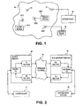
- Fig. 1 is a block diagram of a simple wireless network that might use the present invention.
- Fig. 2 is a block diagram illustrating the coupling between one basic service station and one access point station of the wireless network shown in Fig. 1 .
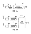
- Fig. 3 is a generalized block diagram of a receive section of station hardware as might be used in hardware illustrated in Fig. 2 with improvements according to embodiments of the present invention;
- Fig. 3A illustrates a single antenna receiver and
- Fig. 3B illustrates a multiple antenna receiver.
- Fig. 4 is a block diagram of a receive section including a whitened-matched filter (WMF) and a symbol-by-symbol minimum distance receiver (SbS MDR).
- WMF whitened-matched filter
- SBS MDR symbol-by-symbol minimum distance receiver
- Fig. 5 is a block diagram of a receive section including a whitened-matched filter (WMF) and an SbS MDR with multiple antennas.
- WMF whitened-matched filter
- Fig. 6 is a block diagram of a receive section including a whitened-matched filter (WMF), an SbS MDR and a feedback filter, with multiple antennas.
- WMF whitened-matched filter
- SbS MDR SbS MDR
- Fig. 7 is a block diagram illustrating one combination of a channel matched filter and a whitening filter.
- Fig. 8 is a block diagram illustrating another combination of channel matched filters, prior to a summer, and a whitening filter following the summer.
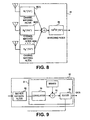
- Fig. 9 is a block diagram of one implementation of an SbS MDR.
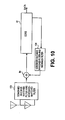
- Fig. 10 is a block diagram of a receive section including a first combined filter combining a matched filter and WMF and a second combined filter combining the matched filter and a feedback filter.
- Fig. 11 is a block diagram of a receive section including a distinct channel matched filter, a first combined filter combining a matched filter and a whitening filter and a second combined filter combining the matched filter and a feedback filter.
- Fig. 12 is a block diagram of a multi-antenna receive section including a mean-square error equalizer, a complimentary code keying ("CCK”) correlator and a slicer.
- CCK complimentary code keying
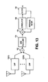
- Fig. 13 is a block diagram of a multi-antenna receive section including a mean-square error equalizer, a CCK correlator, a slicer and a feedback filter.
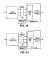
- Fig. 14 is a block diagram of an SbS MDR for a Barker demodulator, including a Barker correlator and a Barker slicer.
- Fig. 15 is a block diagram of an SbS MDR for a CCK demodulator, including a CCK correlator and a CCK slicer.
- Fig. 1 illustrates a simple wireless network that might use the present invention.
- a wireless network 10 comprises a plurality of stations 12 wherein each station 12 is capable of communicating with at least one other station 12 of wireless network 10.
- wireless network 10 is a local area wireless network, as might be used within a building, campus, vehicle or similar environments.
- wireless network 10 is designed to be compliant with one or more of the IEEE 802.11 standards. However, it should be understood that other standards and nonstandard networks might be substituted therefore to solve problems similar to those solved in the 802.11 environment.
- Fig. 1 is intended to be a simplified and generalized diagram of a wireless network. Interfering signal generators are not shown, but are assumed to be present.
- client devices 14 include laptops, personal digital assistants (PDAs), or any other portable or semi-portable electronic device needing to communicate with other devices, or a stationary electronic device needing to communicate with other devices where a wire connection to a network or the other devices is not available or easily provided.
- Access points 16 couple their respective stations to a distribution system. Examples of such distribution systems include the Internet, a local area network (LAN) or a public or private connection to a TCP/IP packet network or other packet network or networks.
- LAN local area network
- TCP/IP packet network or other packet network or networks.
- a plurality of station devices are outfitted with circuitry and/or software that implements a station 12 functionality and one or more network access points are provided in wireless network 10 to provide access between such a station device and the network to which a wired network interface is coupled.
- a station coupled to a wired network interface is referred to as an "access point".
- An access point Just one example of the uses of such a system is to connect computers within a building to a network without requiring network wires to be run to each computer. In that example, the building would be outfitted with stationary access points coupled to the network which are within wireless communication range of wireless network cards in each of the stations coupled to the network.
- Fig. 2 shows in more detail the coupling between one device and one network connection.
- client device 14 is coupled to a device I/O section of client station hardware 20.
- Client station hardware 20 includes a transmit section and a receive section, each coupled to the device I/O section.
- the transmit section transmits a signal through a wireless channel 21 to a receive section of access point hardware 22.
- That receive section is coupled to a network I/O section, thus providing a data communication path from client device 14 to a distribution system 28 such as a local area network.
- a path from distribution system 28 to client device 14 is also provided, via the network I/O section of access point hardware 22, a transmit section of access point hardware 22, a receive section of client station hardware 20 and the device I/O section of client station hardware 20.
- wireless channel 21 depend on many factors, such as the location of client station hardware 20 and access point hardware 22 as well as intervening objects, such as walls, buildings and natural obstructions, as well as influences by other devices and transmitters and receivers and signal-reflecting surfaces.
- the stations can be implemented by dedicated hardware, a general purpose processor running station code, or a combination thereof.
- client station hardware 20 can be integrated in with client device 14.
- client station hardware 20 might be an add-on PCMCIA card that is inserted into the laptop's PCMCIA slot.
- access point hardware 22 is implemented as part of a wired network interface device that is just used to couple a wired network to a wireless network. Notwithstanding the typical implementation, it should be understood that nothing here prevents the diagram of Fig. 2 from being entirely symmetrical, i.e., wherein client station hardware 20 and access point hardware 22 are nearly identical instances of hardware devices, however in many cases, an access point will be fixed and the station that is not an access point is a portable or mobile device where power usage, cost, weight and/or size are considerations.
- Fig. 3 illustrates components of a receive section.
- Fig. 3A illustrates a receiver 30 with a single receive antenna
- Fig. 3B illustrates a receiver 40 with multiple receive antennas.
- Receiver 30 is shown comprising an RF section 32 that receives a signal from an antenna and provides a baseband digital signal 36 to a digital signal processing (“DSP") section 34, which outputs (data output 38) the receiver's best estimate of the transmitted data that resulted in the received signal.
- DSP digital signal processing
- the baseband signal is digitized at an input of DSP section 34.
- Receiver 40 is shown comprising a plurality of RF sections 42 that receive signals from their respective antennas and provide a baseband signal to single antenna processing sections 44, which then provide their output, typically in digital form, to a multi-antenna processing section 46 that combines the information over multiple antennas to form a data output 48, which is the receiver's best estimate of the transmitted data that resulted in the received signal.
- Section 46 might include digital signal processing instructions for implementing complimentary code keying ("CCK”) and/or Barker demodulation processes. If implemented by digital signal processing, single antenna processing sections 44 and multi-antenna processing section 46 might be implemented by code running on one processor, but where plural processing units or processors are available, some parallel processing might occur. For example, one or more section 44, but less than all, might run on one processor while other processors handle the other sections.
- the instances are numbered from “1" to “n” with the understanding that the value of "n” need not be identical from use to use.
- “n” is used as the number of antennas in various places, but that number might vary from example to example. It should also be understood that nothing here requires that all instances be used.
- the receiver illustrated in Fig. 3B might be designed with ten antennas, but only seven of which are being used. This may be for power-saving purposes, because they are not needed when a signal is sufficiently clear, or because the signal levels on the unused antennas are too low to provide a contribution to the detecting process.
- the number of antennas can be from one to twenty, or more than twenty.
- the following disclosure describes the use of multiple receive antennas for mitigating the distortion caused by the frequency selectivity of the wireless channel, but aspects of what is described might be used as well with single receive antenna receivers.
- the signals are modulated using Barker and CCK modulation, as these are common and widespread modulations used in wireless systems today, however it should be understood that the teachings of this disclosure are applicable to other existing, and later developed, modulation schemes, unless indicated otherwise.
- Using multiple receive antennas for a Barker/CCK receiver with appropriate signal processing can provide increased resistance to frequency-selective channel distortion as compared to single receive antenna systems.
- a simple example of this is the reduction in effective delay spread that occurs when the receive antennas are processed with a bank of channel matched filters and the results combined.
- the combined channel/channel matched filter responses combine coherently for the peak correlation value and destructively away from the peak. In the combining process, the channel side lobes are reduced and the channel is effectively shorter.
- This simple scheme can be used to enhance the performance of single antenna signal processing schemes by acting as a front-end that reduces the delay spread into the rest of the receiver.
- a whitened-matched filter is provided in a receiver chain prior to an SbS MDR, as illustrated in Fig. 4 .
- a signal might be received by an antenna 60 and provided to a whitened-matched filter ("WMF") 62, possibly via an RF circuit and/or analog-to-digital (A/D) converter, not shown.
- WMF whitened-matched filter
- A/D analog-to-digital
- SbS MDR 64 determines a minimum distance computed over a single symbol, such as a collection of CCK chips that comprise one CCK symbol. It should be noted that, when used as taught herein, the SbS MDR is much more efficient in an implementation than an MDR that operates over a packet or sequence of symbols. In the absence of ISI, the performance would be the same between the SbS MDR and the full MDR, but typically a packet will comprise multiple symbols in quick succession.
- the WMF By using the WMF, pre-cursor ISI is compensated for, the DFE compensates for post-cursor ISI and the SbS MDR deals with ICI (over the CCK chips, Barker Chips, or the like), as the SbS MDR is applied to the received samples on a symbol-by-symbol basis after the ISI is removed resulting in the benefits of a full MDR, but with much less complexity.
- the WMF/DFE combination compensates for the ISI so the input to the SbS MDR should be free of ISI, but may contain ICI.
- the SbS MDR takes into account the ICI when making symbol decisions.
- the coding used can be either Barker coding or CCK coding for 802.11 signaling, or other coding depending on the signaling protocols used.
- Barker coding is robust enough, relative to CCK coding, that multiple antennas, an SbS MDR and a WMF might not be needed to achieve sufficient performance.
- Fig. 5 illustrates a similar improved receiver, having multiple antennas.
- a plurality of signals might be received by antennas 70(1)...70(n) and provided to a whitened-matched filter (“WMF") 72 that combines contributions from the plurality of antennas.
- WMF 72 is provided to an SbS MDR 74, which then outputs the received data.
- the output of WMF 72 could be one signal, or one signal per active antenna, or one signal per antenna.
- An example implementation of WMF 72 with a single signal output is illustrated in Fig. 8 , wherein channel matched filters are applied, the channels combined and then a whitening filter applied, where the whitening filter is built using the combined channel response.
- Fig. 6 illustrates an improved receiver having multiple antennas similar to that of Fig. 5 , further including feedback.
- a plurality of signals might be received by antennas 80(1)...80(n) and provided to a whitened-matched filter ("WMF") 81 that combines contributions from the plurality of antennas.
- the receiver also includes an SbS MDR 82 and a feedback filter 83.
- the output of feedback filter 83 is combined with the output of WMF 81 by a summer 84.
- the output of summer 84 forms an input to SbS MDR 82 and SbS MDR 82 provides signals at its one or more output that form the detected data stream and an input to feedback filter 83.
- Feedback filter 83 together with a decision block, such as a slicer (not shown), in SbS MDR 82 effects a decision feedback equalizer ("DFE").
- DFE decision feedback equalizer
- summer 84 may be complex adder that adds the signals.
- many of the functional blocks are implemented by digital signal processing code and/or hardwired logic. In such implementations, summer 84 might by fully implemented by a single "add" instruction.
- Fig. 7 is a more detailed block diagram of one implementation of whitened-matched filter (“WMF”) 72 shown in Fig. 5 , for a single antenna receiver.
- WMF 72 combines a channel matched filter (“CMF”) 76 and a whitening filter (“WF”) 78.
- CMF 76 and WF 78 might be integrated such that they are not distinct objects.
- CMF 76 might be implemented as H *(1/ z *) where H(z) is the z-transform of the channel.
- WF 78 might be implemented to perform the filtering function shown in Equation 4, below.
- Fig. 8 is a more detailed block diagram as a counterpart to Fig. 7 , but wherein multiple antennas are considered.
- WMF 81 comprises a plurality of channel matched filters 86, whose outputs are combined by a summer 87 that provides its sum output as an input to a whitening filter ("WF") 88.
- WF 88 might be identical to WF 78, but it might also be different.
- WF 88 may be designed to be the reciprocal maximum-phase spectral factor of the combined channel response.
- filters are implemented as instructions for hardwired logic or digital signal processor code, the functions of filters 86, summer 87 and filter 88 might be integrated such that they are not distinct objects.
- the output of the WMF is a signal that is "minimum-phase", which is a property that ensures that samples used in detecting a symbol that maximize SNR have smearing solely from previous symbols, i.e., little or no pre-cursor energy.
- An SbS MDR and a DFE applied to the output of a channel matched filter does not provide the highest SNR and lowest amount of pre-cursor ISI energy (i.e., the energy of ISI contributed by samples transmitted after the sample under consideration).
- a combination of an SbS MDR with a decision feedback equalizer applied to the output of a whitened-matched filter provides an optimal trade-off between maximizing SNR and minimizing pre-cursor distortion.
- the "minimum-phase" property of the output of the WMF is a property that squarely addresses the trade-off described above. This might be illustrated by the following equations.
- H(z) represents the z-transform of the channel
- the spectrum of the channel can be factored as shown in Equation 3, such that the component G(z) has all of its poles and zeros inside the unit circle.
- S H z A H 2 ⁇ G z ⁇ G * 1 / z *
- a linear system whose poles and zeros are all inside the unit circle is "minimum-phase".
- S H ( z ) the combined response of the channel and channel matched filter will have z-transform given by S H ( z ) in Equation 3.
- a filter with z-transform shown in Equation 4 the output of the matched filter, the resulting signal will be minimum-phase.
- the DFE benefits from a minimum-phase signal, as that signal has desirable properties. For example, some samples are used in detecting a symbol and the selection of samples that maximizes the SNR is a selection of samples for which it is expected that any smearing that occurs will be solely from previous symbols, which the DFE attempts to cancel out. Applying a whitened-matched filter and a DFE at the symbol level instead of the chip level improves performance.
- a filter with the z-transform shown in Equation 4 is referred to as a whitening filter.
- the combined response of a channel matched filter and a whitening filter is referred to as the whitened-matched filter.
- both the whitened-matched filter and data decisions are applied to individual chips.
- data decisions can be made on groups of chips (i.e., symbols) and there are benefits to considering a group of chips as a whole rather than trying to decide on each chip in isolation.
- CCK modulation for example.
- a CCK symbol comprises eight chips. If a receiver made hard decisions at the chip level, it would lose the processing gain that comes from the CCK modulation. In order to keep this gain, typically a full eight chips from a symbol need to be processed prior to detection.
- the output of the whitened-matched filter With an output collected into sets of 8 samples, the result is a large number of possible symbols for the SbS MDR to select from.
- the SbS MDR attempts to minimize a distance value, D, for each collection, r k , of receive samples according to an equation such as Equation 5, wherein s l represents one of the possible transmit symbols, G k represents matrices with rows corresponding to the impulse response of the minimum-phase spectral factor of the channel and the sum is over all possible transmit symbols.
- D ⁇ r ⁇ k - ⁇ l ⁇ k G k - l ⁇ s ⁇ l ⁇ 2
- Equation 5 can be then written as shown in Equation 6.
- D ⁇ r ⁇ k - G 1 ⁇ s ⁇ k - 1 - G 0 ⁇ s k ⁇ ⁇ 2
- Equation 7 is one mathematical representation of an SbS MDR. Minimizing D from Equation 7 is equivalent to finding the symbol s that maximizes M in Equation 8, where s T and G 0 T are the conjugate transposes of s and Go, respectively.
- M Re s ⁇ T ⁇ G 0 T ⁇ r ⁇ k - 1 2 ⁇ ⁇ G 0 ⁇ s ⁇ ⁇ 2
- An example of such an implementation of an SbS MDR is shown in Fig. 9 .
- Fig. 9 shows one example of an SbS MDR 90 (as SbS MDR 82 in Fig. 6 , for example) in greater detail, including an SbS MDR matched filter ("SMMF") 92 and a core 91 comprising a correlator 94, a summer 95, correction weights 96 and a slicer 98.
- SMMF 92 matches SbS MDR 90 to the combined response of the channel and the WMF (not shown here; example: WMF 81 in Fig. 6 ).
- An output of correlator 94 is summed with correction weights 96 by summer 95, which provides its result to slicer 98.
- corrections are applied to the output of correlator 94 prior to slicing.
- the correction weights correspond to energy in a symbol at the output off the channel, which are preferably subtracted from the correlator output prior to slicing.
- Correlator 94 can be a CCK correlator or a Barker correlator or other correlator, depending on the code being used.
- SMMF 92 can be combined with the WMF and feedback filter to reduce the overall complexity of the implementation. An example of this is shown in Fig. 10 .
- a filter 100 is a combination of a WMF and the SMMF and the SMMF is also combined with the feedback filter to form a combined filter 104.
- filter 100 is a combination of SMMF 92, shown in Fig. 9 and described above, with WMF 81 described above in connection with Fig. 7 .
- filter 104 is a combination of SMMF 92 with feedback filter 83 described above in connection with Fig. 6 .
- the combination of the SbS MDR matched filter and whitening filter is interesting conceptually as well as in terms of implementation.
- the matrix G 0 T represents truncated versions of the maximum-phase spectral factor of the channel.
- the transfer function of the whitening filter is the reciprocal of the maximum-phase spectral factor of the channel, so application of G 0 T to the output of the whitening filter gives rise to cancellation in the combined response.
- the cancellation is cyclo-stationary with regards to the chips in the symbol. That is, the combined response for the first chip in a symbol will be nearly the identity. The combined response for the last chip in a symbol will be the nearly that of the whitening filter. This generates an effect wherein the whitening filter is removing ISI, but not ICI.
- Fig. 11 illustrates an allocation of filter function that takes advantage of this.
- a CMF 110 receives inputs from antennas and provides results to a combined filter 112 that combines a matched filter (such as SMMF 92 of Fig. 9 ) and a whitening filter (such as WF 78 in Fig. 7 ).
- the results of the combined filter 112 are added to a feedback filter 104 output as described earlier.
- the feedback filter 104 includes the matched filter as well.
- CMF 110 is implemented such that it is shorter than the channel, the SMMF that is part of combined filter 112 will not comprise the maximum-phase spectral factor of the channel. If CMF 110 is not so implemented, it can still work, but computation of the filter coefficients is a more complex operation.
- a Levinson recursion might be used, but other approaches can be used.
- the autocorrelation of the channel response is as shown in Equation 11.
- a Levinson recursion solves the system shown in Equation 12 for the forward prediction-error coefficients ⁇ a i ⁇ .
- a forward prediction-error filter (an intermediate step in building filters shown in the figures) corresponds to the filter with response: 1 G z .
- the filter with coefficients given by the conjugate time reversal of the forward predictions-error coefficients has response: 1 G * 1 / z * .
- the result is a whitening filter up to a scale factor.
- the scale factor A H 2 corresponds to the mean-square prediction error and can be obtained from the Levinson recursion.
- the Levinson recursion recursively generates increasingly better approximations to the whitening filter.
- w ( z ) -.03 + .06 z -1 -.12 z -2 +.25 z - 3
- the minimum-phase spectral factor of the channel auto-correlation is the channel response.
- the maximum-phase spectral factor is obtained by conjugating and time reversing the coefficients of the minimum-phase spectral factor.
- G 0 and G 1 shown in Equations 16, 17, respectively, represent the portions of a convolution matrix with coefficients given by the minimum-phase spectral factor that operate and the current and previous symbol respectively.
- Equation 18 The matrix G 0 T shown in Equation 18 corresponds to the operations of the additional matched filter.
- G 0 T 1 .5 0 0 0 0 0 0 0 0 1 .5 0 0 0 0 0 0 0 0 0 1 .5 0 0 0 0 0 0 0 0 0 0 1 .5 0 0 0 0 0 0 0 0 0 0 1 .5 0 0 0 0 0 0 0 0 0 0 1 .5 0 0 0 0 0 0 0 0 0 0 1 .5 0 0 0 0 0 0 0 0 0 0 0 0 0 1 .5 0 0 0 0 0 0 0 0 0 0 0 0 0 1 .5 0 0 0 0 0 0 0 0 0 0
- the feedback filter operates as follows. When processing the first chip of a symbol, is subtracts off 0.5 the value of the last chip of the previous symbol. In general, the feedback structure will be more complex.
- the combined additional matched filter and whitening filter operate as follows. For the first seven chips of a symbol, the output of the matched filter passes through unchanged. For the last chip of the symbol, use the output of the whitened-matched filter.
- the output of the DFE is fed to the CCK correlator. Correction weights are applied to the output of the correlator prior to the making of symbol decisions. These weights correspond to the energy of each symbol at the correlator input. For each symbol s k , compute ⁇ G 0 s k ⁇ 2 .
- CCK symbol s ⁇ 1,1,1,-1,1,1,-1,1 ⁇ .
- G 0 ⁇ s 1 1.5 1.5 - .5 .5 1.5 - .5 .5 ⁇
- Fig. 12 is a block diagram of a multi-antenna receive section including a plurality of channel matched filters 120, a summer 122, a mean-square error (MSE) equalizer 124, a complimentary code keying (“CCK”) correlator 126 and a slicer 128.
- MSE mean-square error
- CCK complimentary code keying
- a similar section might be used for Barker codes.
- Fig. 13 is a block diagram of a variation of the multi-antenna receive section of Fig. 12 .
- a summer 129 is interposed between MSE equalizer 124 and CCK correlator 126 to add in an output of a feedback filter 130.
- Fig. 14 is a block diagram of an SbS MDR for a Barker demodulator, including a Barker correlator and a Barker slicer.
- the number of correction weights for the Barker correlator could be four or some other number.
- Fig. 15 is a block diagram of an SbS MDR for a CCK demodulator, including a CCK correlator and a CCK slicer.
- a combined filter that combines a whitening filter and an additional matched into one filter gives rise to an efficient computation of filter coefficients as well as an efficient implementation of the filtering operations.
- the additional matched filter may be a truncated version of the inverse of the whitening filter, for additional efficiency gains.
- the CMF channel matched filter
- the feed-forward and feed-back equalizers equalize the combined channel response. This separation of processing requires fewer computations than if the receiver tries to equalize each receive chain separately.
- the design is more flexible since the equalization/detection portion of the design works the same for any number of receive chains.
Landscapes
- Engineering & Computer Science (AREA)
- Computer Networks & Wireless Communication (AREA)
- Signal Processing (AREA)
- Physics & Mathematics (AREA)
- Mathematical Physics (AREA)
- Power Engineering (AREA)
- Radio Transmission System (AREA)
- Cable Transmission Systems, Equalization Of Radio And Reduction Of Echo (AREA)
- Noise Elimination (AREA)
- Input Circuits Of Receivers And Coupling Of Receivers And Audio Equipment (AREA)
- Burglar Alarm Systems (AREA)
- Circuits Of Receivers In General (AREA)
Claims (8)
- Funkempfänger bzw. drahtloser Empfänger zum Datenempfang über einen Funk-Kanal, mit:einer Mehrzahl von Antennen (70(1..N), 80(1..N)) zum Empfang von Signalen, umfassend eine Erfassung von Empfangs-Proben, wobei die Signale eine derartige Signal-Vielfalt aufweisen, dass das, was von dem Funk-Kanal empfangen wird, an jeder der Mehrzahl von Antennen (70(1..N), 80(1..N)) nicht identisch ist;einem ersten Filter, umfassend einen Channel-matched-Filter (100) und einen Whitened-matched-Filter (100; 112), zum Empfangen von einem oder mehreren der Signale, empfangen von der Mehrzahl von Antennen (70(1..N), 80(1..N)), und Ausgeben einer Vielzahl von gefilterten Signalen, wobei der Whitened-matched-Filter an dem einen oder mehreren Signalen gemäß einem kombinierten Filter (100; 112) unter Implementierung eines Matched-Filters und eines Whitening-Filters arbeitet;einem zweiten Filter (104) mit einer Übertragungsfunktion, die eine Kombination von dem Channel-matched-Filter und einem Feedback-Filter ist; undeinem Symbol-by-Symbol-Minimum-Distance-Receiver (SbS MDR) zum Empfang von der Vielzahl von gefilterten Signalen aus einer Summe von dem ersten Filter und dem zweiten Filter und Ausgeben eines resultierenden Datenstroms zu einem Output und dem zweiten Filter,wobei der SbS MDR zur Selektion eines Symbols aus dem Satz von möglichen Symbolen ausgelegt ist, was die Distanz zwischen der Erfassung von Empfangsproben und dem Satz an möglichen Symbolen minimiert, unter Berücksichtigung der geschätzten Kanal-Response aufgrund dieses Symbols.
- Funkempfänger nach Anspruch 1, wobei der erste Filter eine Übertragungs-Funktion aufweist, die eine Kombination von dem Channel-matched-Filter (100) und dem Whitened-matched-Filter (100; 112) darstellt.
- Funkempfänger nach Anspruch 1 oder 2, wobei der Channel-matched-Filter (100) ein SbS MDR-matched-Filter, abgestimmt auf eine Response des Whitened-matched-Filters und des Funk-Kanals, ist.
- Funkempfänger nach einem der vorangehenden Ansprüche, wobei der SbS MDR zur Minimierung eines Distanz-Werts D konfiguriert ist, wobei D=∥ r k -G 0 s k ∥2 für die Erfassung von den Empfangs-Proben rk und einem möglichen Sende-Symbol sk ist.
- Funkempfänger nach einem der vorangehenden Ansprüche, wobei der Channel-matched-Filter, der in den ersten Filter implementiert ist, ein SbS MDR-matched-Filter, abgestimmt auf eine Response von dem Whitened-matched-Filter und dem Funk-Kanal, ist.
- Funkempfänger nach einem der vorangehenden Ansprüche, wobei der Channel-matched-Filter, der in den zweiten Filter implementiert ist, ein SbS MDR-matched-Filter, abgestimmt auf eine Response von dem Whitened-matched-Filter und dem Funk-Kanal, ist.
- Funkempfänger nach einem der vorangehenden Ansprüche, weiterhin umfassend digitale Signalverarbeitungs-Logik zum Verarbeiten von Signalen, empfangen von der Mehrzahl von Antennen (70(1..N), 80(1..N)), wobei die Signale eines oder mehrere von Barker-modulierten Signalen und Complementary Code Keying (CCK)-Signalen, sind.
- Funkempfänger nach einem der vorangehenden Ansprüche, wobei der Funkempfänger einen Decision-Feedback-Equalizer, der zum Empfang von gefilterten Signalen von dem Whitened-matched-Filter ausgelegt ist, implementiert.
Applications Claiming Priority (2)
| Application Number | Priority Date | Filing Date | Title |
|---|---|---|---|
| US10/643,155 US7127013B2 (en) | 2003-08-18 | 2003-08-18 | Spacetime equalization in a wireless receiver |
| PCT/US2004/026566 WO2005020495A2 (en) | 2003-08-18 | 2004-08-13 | Spacetime equalization in a wireless receiver |
Publications (3)
| Publication Number | Publication Date |
|---|---|
| EP1665613A2 EP1665613A2 (de) | 2006-06-07 |
| EP1665613A4 EP1665613A4 (de) | 2006-10-25 |
| EP1665613B1 true EP1665613B1 (de) | 2011-01-12 |
Family
ID=34193808
Family Applications (1)
| Application Number | Title | Priority Date | Filing Date |
|---|---|---|---|
| EP04781282A Expired - Lifetime EP1665613B1 (de) | 2003-08-18 | 2004-08-13 | Raumzeit-entzerrung in einem drahtlosen empfänger |
Country Status (10)
| Country | Link |
|---|---|
| US (2) | US7127013B2 (de) |
| EP (1) | EP1665613B1 (de) |
| JP (1) | JP4782678B2 (de) |
| CN (1) | CN1836395B (de) |
| AT (1) | ATE495597T1 (de) |
| AU (1) | AU2004302528B2 (de) |
| CA (1) | CA2536014A1 (de) |
| DE (1) | DE602004031027D1 (de) |
| TW (1) | TW200514373A (de) |
| WO (1) | WO2005020495A2 (de) |
Families Citing this family (10)
| Publication number | Priority date | Publication date | Assignee | Title |
|---|---|---|---|---|
| CN100340068C (zh) | 2002-04-22 | 2007-09-26 | Ipr许可公司 | 多输入多输出无线通信方法及具有无线前端部件的收发机 |
| US7496164B1 (en) | 2003-05-02 | 2009-02-24 | At&T Mobility Ii Llc | Systems and methods for interference cancellation in a radio receiver system |
| US7450924B1 (en) * | 2004-03-25 | 2008-11-11 | At&T Mobility Ii Llc | Interference cancellation and receive diversity for single-valued modulation receivers |
| JP4666150B2 (ja) * | 2005-05-31 | 2011-04-06 | 日本電気株式会社 | Mimo受信装置、受信方法、および無線通信システム |
| EP1806889A1 (de) * | 2006-01-09 | 2007-07-11 | Nokia Corporation | Vorrichtung und Verfahren zum Empfang von über einen gestörten Kanal übertragenen Signalen |
| WO2007130578A2 (en) * | 2006-05-04 | 2007-11-15 | Quantenna Communications, Inc. | Multiple antenna receiver system and method |
| US8031794B2 (en) * | 2006-05-09 | 2011-10-04 | At&T Mobility Ii Llc | Systems and methods for interference cancellation in a multiple antenna radio receiver system |
| US7899110B1 (en) | 2006-12-27 | 2011-03-01 | Marvell International Ltd. | Bit sync for receiver with multiple antennas |
| US7724844B2 (en) * | 2007-01-31 | 2010-05-25 | Seagate Technology Llc | Detection of servo data for a servo system |
| WO2022223100A1 (en) * | 2021-04-20 | 2022-10-27 | Nokia Solutions And Networks Oy | Interference rejection in cooperative multi-point communication |
Family Cites Families (15)
| Publication number | Priority date | Publication date | Assignee | Title |
|---|---|---|---|---|
| US6233273B1 (en) * | 1999-06-29 | 2001-05-15 | Intersil Americas Inc. | Rake receiver with embedded decision feedback equalizer |
| US6690715B2 (en) * | 1999-06-29 | 2004-02-10 | Intersil Americas Inc. | Rake receiver with embedded decision feedback equalizer |
| US6560299B1 (en) * | 1999-07-30 | 2003-05-06 | Christopher H Strolle | Diversity receiver with joint signal processing |
| US6628702B1 (en) * | 2000-06-14 | 2003-09-30 | Qualcomm, Incorporated | Method and apparatus for demodulating signals processed in a transmit diversity mode |
| US6882692B2 (en) * | 2000-12-29 | 2005-04-19 | Sharp Laboratories Of America, Inc. | Fast transform system for an extended data rate WLAN system |
| EP1223717B1 (de) | 2001-01-15 | 2006-08-02 | Lucent Technologies Inc. | Verfahren zur Maximum-Likelihood-Bestimmung unter Verwendung eines Empfängers mit Sequenzschätzung |
| US7006563B2 (en) * | 2001-02-01 | 2006-02-28 | Broadcom Corporation | Decision feedback equalizer for minimum and maximum phase channels |
| FR2828615B1 (fr) * | 2001-08-10 | 2005-12-02 | Thales Sa | Procede pour augmenter le debit dans un systeme de communication |
| US6760388B2 (en) * | 2001-12-07 | 2004-07-06 | Qualcomm Incorporated | Time-domain transmit and receive processing with channel eigen-mode decomposition for MIMO systems |
| TW538603B (en) * | 2001-12-28 | 2003-06-21 | Realtek Semi Conductor Corp | Receiver for block code in near-minimum phase channel |
| TW576039B (en) * | 2001-12-28 | 2004-02-11 | Realtek Semiconductor Corp | Receiver for block code transmission and the receiving method thereof |
| TWI272776B (en) * | 2001-12-31 | 2007-02-01 | Accton Technology Corp | Complementary code keying demodulation structure |
| US7027538B2 (en) * | 2002-02-14 | 2006-04-11 | Koninklijke Philips Electronics N.V. | Method and system for joint decision feedback equalization and complementary code key decoding using a trellis |
| DE10208416A1 (de) * | 2002-02-27 | 2003-09-25 | Advanced Micro Devices Inc | Interferenzverminderung in CCK-modulierten Signalen |
| DE20321903U1 (de) * | 2002-06-24 | 2012-11-14 | Broadcom Corporation | Antennensystem mit Reduzierter Komplexität, das eineGemultiplexte Empfangskettenverarbeitung verwendet |
-
2003
- 2003-08-18 US US10/643,155 patent/US7127013B2/en not_active Expired - Lifetime
-
2004
- 2004-08-13 DE DE602004031027T patent/DE602004031027D1/de not_active Expired - Lifetime
- 2004-08-13 CN CN2004800237007A patent/CN1836395B/zh not_active Expired - Fee Related
- 2004-08-13 JP JP2006523965A patent/JP4782678B2/ja not_active Expired - Fee Related
- 2004-08-13 AT AT04781282T patent/ATE495597T1/de not_active IP Right Cessation
- 2004-08-13 WO PCT/US2004/026566 patent/WO2005020495A2/en not_active Ceased
- 2004-08-13 AU AU2004302528A patent/AU2004302528B2/en not_active Ceased
- 2004-08-13 EP EP04781282A patent/EP1665613B1/de not_active Expired - Lifetime
- 2004-08-13 CA CA002536014A patent/CA2536014A1/en not_active Abandoned
- 2004-08-17 TW TW093124650A patent/TW200514373A/zh unknown
-
2006
- 2006-08-31 US US11/469,396 patent/US7421047B2/en not_active Expired - Fee Related
Non-Patent Citations (1)
| Title |
|---|
| KAY, STEVEN M.: "Fundamentals of Statistical Signal Processing: Detection Theory", 1 January 1998, PRENTICE HALL SIGNAL PROCESSING SERIES, Upper Saddle River, New Jersey, U.S.A, ISBN: 0-13-505135-X, pages: 112 - 125 * |
Also Published As
| Publication number | Publication date |
|---|---|
| CN1836395A (zh) | 2006-09-20 |
| US7421047B2 (en) | 2008-09-02 |
| US20070002983A1 (en) | 2007-01-04 |
| JP4782678B2 (ja) | 2011-09-28 |
| CN1836395B (zh) | 2010-12-08 |
| EP1665613A2 (de) | 2006-06-07 |
| US20050042997A1 (en) | 2005-02-24 |
| WO2005020495A2 (en) | 2005-03-03 |
| AU2004302528B2 (en) | 2009-01-15 |
| WO2005020495A3 (en) | 2005-06-30 |
| JP2007503171A (ja) | 2007-02-15 |
| ATE495597T1 (de) | 2011-01-15 |
| AU2004302528A1 (en) | 2005-03-03 |
| CA2536014A1 (en) | 2005-03-03 |
| EP1665613A4 (de) | 2006-10-25 |
| TW200514373A (en) | 2005-04-16 |
| DE602004031027D1 (de) | 2011-02-24 |
| US7127013B2 (en) | 2006-10-24 |
Similar Documents
| Publication | Publication Date | Title |
|---|---|---|
| US8553820B2 (en) | Groupwise successive interference cancellation for block transmission with reception diversity | |
| EP0868788B1 (de) | Verfahren und anordnung zur verminderung von nachbarinterferenz unter verwendung von diversity-signalen eines antennenfeldes | |
| US6426973B1 (en) | Differential minimum mean squared error communication signal compensation method | |
| US6243415B1 (en) | Process of multisensor equalization allowing multisensor reception in the presence of interference and multiple propagation paths and receiver for the implementation thereof | |
| CN1902834B (zh) | 用于码分多址通信的方法、装置和系统 | |
| US7289481B2 (en) | WLAN capacity enhancement by contention resolution | |
| AU725732B2 (en) | Method and apparatus for interference decorrelation in time and space | |
| EP0851637A2 (de) | Entscheidungsrückgekoppelter Entzerrer mit einer veränderbaren Anzahl von Abzweigspunkten, und veränderbarer Zuordnung davon, in dem Vorwärtsteil | |
| EP1721475A1 (de) | Mimo-lmmse-sic-empfänger auf der basis eingeschränkter optimierung für die cdma-abwärtsstrecke | |
| WO2004023696A2 (en) | Scaling using gain factors for use in data detection for wireless code division multiple access communication systems | |
| EP1665613B1 (de) | Raumzeit-entzerrung in einem drahtlosen empfänger | |
| EP1530300B1 (de) | Verfahren und Vorrichtung zur Entzerrerung in einem Empfänger eines CDMA Systems | |
| JP3808311B2 (ja) | 受信方法及び受信機 | |
| EP1825610A2 (de) | Verfahren und vorrichtung zur durchführung der chip-level-entzerrung mithilfe gemeinsamer verarbeitung | |
| Koivunen et al. | Blind and Semiblind Channel Estimation | |
| HK1095943A (en) | Spacetime equalization in a wireless receiver |
Legal Events
| Date | Code | Title | Description |
|---|---|---|---|
| PUAI | Public reference made under article 153(3) epc to a published international application that has entered the european phase |
Free format text: ORIGINAL CODE: 0009012 |
|
| 17P | Request for examination filed |
Effective date: 20060320 |
|
| AK | Designated contracting states |
Kind code of ref document: A2 Designated state(s): AT BE BG CH CY CZ DE DK EE ES FI FR GB GR HU IE IT LI LU MC NL PL PT RO SE SI SK TR |
|
| AX | Request for extension of the european patent |
Extension state: AL HR LT LV MK |
|
| RIC1 | Information provided on ipc code assigned before grant |
Ipc: H04B 1/707 20060101ALI20060913BHEP Ipc: H04B 7/08 20060101ALI20060913BHEP Ipc: H04L 1/06 20060101ALI20060913BHEP Ipc: H04L 25/03 20060101ALI20060913BHEP Ipc: H04L 1/02 20060101AFI20050707BHEP Ipc: H04L 1/00 20060101ALI20060913BHEP |
|
| A4 | Supplementary search report drawn up and despatched |
Effective date: 20060925 |
|
| 17Q | First examination report despatched |
Effective date: 20070226 |
|
| RAP1 | Party data changed (applicant data changed or rights of an application transferred) |
Owner name: QUALCOMM INCORPORATED |
|
| GRAP | Despatch of communication of intention to grant a patent |
Free format text: ORIGINAL CODE: EPIDOSNIGR1 |
|
| GRAS | Grant fee paid |
Free format text: ORIGINAL CODE: EPIDOSNIGR3 |
|
| GRAA | (expected) grant |
Free format text: ORIGINAL CODE: 0009210 |
|
| AK | Designated contracting states |
Kind code of ref document: B1 Designated state(s): AT BE BG CH CY CZ DE DK EE ES FI FR GB GR HU IE IT LI LU MC NL PL PT RO SE SI SK TR |
|
| AX | Request for extension of the european patent |
Extension state: AL HR LT LV MK |
|
| REG | Reference to a national code |
Ref country code: GB Ref legal event code: FG4D |
|
| REG | Reference to a national code |
Ref country code: CH Ref legal event code: EP |
|
| REG | Reference to a national code |
Ref country code: IE Ref legal event code: FG4D |
|
| REF | Corresponds to: |
Ref document number: 602004031027 Country of ref document: DE Date of ref document: 20110224 Kind code of ref document: P |
|
| REG | Reference to a national code |
Ref country code: DE Ref legal event code: R096 Ref document number: 602004031027 Country of ref document: DE Effective date: 20110224 |
|
| REG | Reference to a national code |
Ref country code: NL Ref legal event code: VDEP Effective date: 20110112 |
|
| LTIE | Lt: invalidation of european patent or patent extension |
Effective date: 20110112 |
|
| PG25 | Lapsed in a contracting state [announced via postgrant information from national office to epo] |
Ref country code: SE Free format text: LAPSE BECAUSE OF FAILURE TO SUBMIT A TRANSLATION OF THE DESCRIPTION OR TO PAY THE FEE WITHIN THE PRESCRIBED TIME-LIMIT Effective date: 20110112 Ref country code: ES Free format text: LAPSE BECAUSE OF FAILURE TO SUBMIT A TRANSLATION OF THE DESCRIPTION OR TO PAY THE FEE WITHIN THE PRESCRIBED TIME-LIMIT Effective date: 20110423 Ref country code: GR Free format text: LAPSE BECAUSE OF FAILURE TO SUBMIT A TRANSLATION OF THE DESCRIPTION OR TO PAY THE FEE WITHIN THE PRESCRIBED TIME-LIMIT Effective date: 20110413 Ref country code: PT Free format text: LAPSE BECAUSE OF FAILURE TO SUBMIT A TRANSLATION OF THE DESCRIPTION OR TO PAY THE FEE WITHIN THE PRESCRIBED TIME-LIMIT Effective date: 20110512 |
|
| PG25 | Lapsed in a contracting state [announced via postgrant information from national office to epo] |
Ref country code: AT Free format text: LAPSE BECAUSE OF FAILURE TO SUBMIT A TRANSLATION OF THE DESCRIPTION OR TO PAY THE FEE WITHIN THE PRESCRIBED TIME-LIMIT Effective date: 20110112 Ref country code: SI Free format text: LAPSE BECAUSE OF FAILURE TO SUBMIT A TRANSLATION OF THE DESCRIPTION OR TO PAY THE FEE WITHIN THE PRESCRIBED TIME-LIMIT Effective date: 20110112 Ref country code: CY Free format text: LAPSE BECAUSE OF FAILURE TO SUBMIT A TRANSLATION OF THE DESCRIPTION OR TO PAY THE FEE WITHIN THE PRESCRIBED TIME-LIMIT Effective date: 20110112 Ref country code: BG Free format text: LAPSE BECAUSE OF FAILURE TO SUBMIT A TRANSLATION OF THE DESCRIPTION OR TO PAY THE FEE WITHIN THE PRESCRIBED TIME-LIMIT Effective date: 20110412 Ref country code: NL Free format text: LAPSE BECAUSE OF FAILURE TO SUBMIT A TRANSLATION OF THE DESCRIPTION OR TO PAY THE FEE WITHIN THE PRESCRIBED TIME-LIMIT Effective date: 20110112 Ref country code: BE Free format text: LAPSE BECAUSE OF FAILURE TO SUBMIT A TRANSLATION OF THE DESCRIPTION OR TO PAY THE FEE WITHIN THE PRESCRIBED TIME-LIMIT Effective date: 20110112 Ref country code: FI Free format text: LAPSE BECAUSE OF FAILURE TO SUBMIT A TRANSLATION OF THE DESCRIPTION OR TO PAY THE FEE WITHIN THE PRESCRIBED TIME-LIMIT Effective date: 20110112 Ref country code: PL Free format text: LAPSE BECAUSE OF FAILURE TO SUBMIT A TRANSLATION OF THE DESCRIPTION OR TO PAY THE FEE WITHIN THE PRESCRIBED TIME-LIMIT Effective date: 20110112 |
|
| PG25 | Lapsed in a contracting state [announced via postgrant information from national office to epo] |
Ref country code: EE Free format text: LAPSE BECAUSE OF FAILURE TO SUBMIT A TRANSLATION OF THE DESCRIPTION OR TO PAY THE FEE WITHIN THE PRESCRIBED TIME-LIMIT Effective date: 20110112 Ref country code: DK Free format text: LAPSE BECAUSE OF FAILURE TO SUBMIT A TRANSLATION OF THE DESCRIPTION OR TO PAY THE FEE WITHIN THE PRESCRIBED TIME-LIMIT Effective date: 20110112 |
|
| PLBE | No opposition filed within time limit |
Free format text: ORIGINAL CODE: 0009261 |
|
| STAA | Information on the status of an ep patent application or granted ep patent |
Free format text: STATUS: NO OPPOSITION FILED WITHIN TIME LIMIT |
|
| PG25 | Lapsed in a contracting state [announced via postgrant information from national office to epo] |
Ref country code: SK Free format text: LAPSE BECAUSE OF FAILURE TO SUBMIT A TRANSLATION OF THE DESCRIPTION OR TO PAY THE FEE WITHIN THE PRESCRIBED TIME-LIMIT Effective date: 20110112 Ref country code: RO Free format text: LAPSE BECAUSE OF FAILURE TO SUBMIT A TRANSLATION OF THE DESCRIPTION OR TO PAY THE FEE WITHIN THE PRESCRIBED TIME-LIMIT Effective date: 20110112 Ref country code: CZ Free format text: LAPSE BECAUSE OF FAILURE TO SUBMIT A TRANSLATION OF THE DESCRIPTION OR TO PAY THE FEE WITHIN THE PRESCRIBED TIME-LIMIT Effective date: 20110112 |
|
| 26N | No opposition filed |
Effective date: 20111013 |
|
| PG25 | Lapsed in a contracting state [announced via postgrant information from national office to epo] |
Ref country code: IT Free format text: LAPSE BECAUSE OF FAILURE TO SUBMIT A TRANSLATION OF THE DESCRIPTION OR TO PAY THE FEE WITHIN THE PRESCRIBED TIME-LIMIT Effective date: 20110112 |
|
| REG | Reference to a national code |
Ref country code: DE Ref legal event code: R097 Ref document number: 602004031027 Country of ref document: DE Effective date: 20111013 |
|
| PG25 | Lapsed in a contracting state [announced via postgrant information from national office to epo] |
Ref country code: MC Free format text: LAPSE BECAUSE OF NON-PAYMENT OF DUE FEES Effective date: 20110831 |
|
| REG | Reference to a national code |
Ref country code: CH Ref legal event code: PL |
|
| PG25 | Lapsed in a contracting state [announced via postgrant information from national office to epo] |
Ref country code: CH Free format text: LAPSE BECAUSE OF NON-PAYMENT OF DUE FEES Effective date: 20110831 Ref country code: LI Free format text: LAPSE BECAUSE OF NON-PAYMENT OF DUE FEES Effective date: 20110831 |
|
| REG | Reference to a national code |
Ref country code: FR Ref legal event code: ST Effective date: 20120430 |
|
| REG | Reference to a national code |
Ref country code: IE Ref legal event code: MM4A |
|
| PG25 | Lapsed in a contracting state [announced via postgrant information from national office to epo] |
Ref country code: IE Free format text: LAPSE BECAUSE OF NON-PAYMENT OF DUE FEES Effective date: 20110813 |
|
| PG25 | Lapsed in a contracting state [announced via postgrant information from national office to epo] |
Ref country code: FR Free format text: LAPSE BECAUSE OF NON-PAYMENT OF DUE FEES Effective date: 20110831 |
|
| PG25 | Lapsed in a contracting state [announced via postgrant information from national office to epo] |
Ref country code: LU Free format text: LAPSE BECAUSE OF NON-PAYMENT OF DUE FEES Effective date: 20110813 |
|
| PG25 | Lapsed in a contracting state [announced via postgrant information from national office to epo] |
Ref country code: TR Free format text: LAPSE BECAUSE OF FAILURE TO SUBMIT A TRANSLATION OF THE DESCRIPTION OR TO PAY THE FEE WITHIN THE PRESCRIBED TIME-LIMIT Effective date: 20110112 |
|
| PG25 | Lapsed in a contracting state [announced via postgrant information from national office to epo] |
Ref country code: HU Free format text: LAPSE BECAUSE OF FAILURE TO SUBMIT A TRANSLATION OF THE DESCRIPTION OR TO PAY THE FEE WITHIN THE PRESCRIBED TIME-LIMIT Effective date: 20110112 |
|
| PGFP | Annual fee paid to national office [announced via postgrant information from national office to epo] |
Ref country code: DE Payment date: 20170825 Year of fee payment: 14 Ref country code: GB Payment date: 20170725 Year of fee payment: 14 |
|
| REG | Reference to a national code |
Ref country code: DE Ref legal event code: R119 Ref document number: 602004031027 Country of ref document: DE |
|
| GBPC | Gb: european patent ceased through non-payment of renewal fee |
Effective date: 20180813 |
|
| PG25 | Lapsed in a contracting state [announced via postgrant information from national office to epo] |
Ref country code: DE Free format text: LAPSE BECAUSE OF NON-PAYMENT OF DUE FEES Effective date: 20190301 |
|
| PG25 | Lapsed in a contracting state [announced via postgrant information from national office to epo] |
Ref country code: GB Free format text: LAPSE BECAUSE OF NON-PAYMENT OF DUE FEES Effective date: 20180813 |