EP1665936A1 - Verfahren und Vorrichtung zur Bearbeitung von Schlachtgeflügel - Google Patents
Verfahren und Vorrichtung zur Bearbeitung von Schlachtgeflügel Download PDFInfo
- Publication number
- EP1665936A1 EP1665936A1 EP06075285A EP06075285A EP1665936A1 EP 1665936 A1 EP1665936 A1 EP 1665936A1 EP 06075285 A EP06075285 A EP 06075285A EP 06075285 A EP06075285 A EP 06075285A EP 1665936 A1 EP1665936 A1 EP 1665936A1
- Authority
- EP
- European Patent Office
- Prior art keywords
- bird
- processing
- sternum
- conveyor
- legs
- Prior art date
- Legal status (The legal status is an assumption and is not a legal conclusion. Google has not performed a legal analysis and makes no representation as to the accuracy of the status listed.)
- Granted
Links
Images




Classifications
-
- A—HUMAN NECESSITIES
- A22—BUTCHERING; MEAT TREATMENT; PROCESSING POULTRY OR FISH
- A22C—PROCESSING MEAT, POULTRY, OR FISH
- A22C21/00—Processing poultry
-
- A—HUMAN NECESSITIES
- A22—BUTCHERING; MEAT TREATMENT; PROCESSING POULTRY OR FISH
- A22C—PROCESSING MEAT, POULTRY, OR FISH
- A22C21/00—Processing poultry
- A22C21/0023—Dividing poultry
-
- A—HUMAN NECESSITIES
- A22—BUTCHERING; MEAT TREATMENT; PROCESSING POULTRY OR FISH
- A22C—PROCESSING MEAT, POULTRY, OR FISH
- A22C21/00—Processing poultry
- A22C21/0053—Transferring or conveying devices for poultry
Definitions
- the invention relates to a method and device for processing a slaughtered bird which is hung by its legs from a hook of a moving conveyor. Methods and devices of this nature are generally known.
- a special processing operation carried out on a slaughtered and eviscerated bird is a partial processing operation in which an automatic or semi-automatic processing device is used to obtain bird parts which are each of substantially identical weight or contain an equal amount of meat, irrespective of the body part (such as breast, wing, thigh, drumstick) which the bird part comprises. Since the amount of meat per bird part is relatively limited, the division must be carried out as accurately and reproducibly as possible, in order to keep differences in weight or amount of meat between the different bird parts within predetermined limits. A division which satisfies this requirement can only be carried out if the bird is accurately positioned in the processing device. The known methods and devices are not entirely satisfactory with regard to this point.
- EP-B-0,033,177 describes a device for dividing a bird into nine parts, each of substantially the same weight.
- the bird has to be manually arranged on a positioning support which acts on the bird at the location of the ankle joints and the wings, and also supports the bird at the sides of the body, the top of the thighs, behind the spinal column and on the back.
- various blades are used to automatically cut through the carcass, the breast and a first wing being cut off successively, and then a body longitudinal-halving cut being made, the other wing and the complete legs being cut off, and the drumsticks being cut free from the thighs.
- a drawback of the device described in EP-B-0,033,177 is that it is not suitable for picking up and processing birds which have been supplied in a conveyor, such as an overhead suspension conveyor, without human intervention; the birds have to be arranged manually on the positioning supports. Furthermore, the bird is not optimally positioned on the positioning support.
- EP-A-0,545,040 describes a device for cutting off a breast part of a bird, the wings already having been removed from the bird.
- the bird is hung by its legs from a hook and is internally supported by means of a mandrel which substantially fills the body cavity and causes the breast of the bird to project outwardly by exerting pressure on the ribs of the chest.
- a pivotable retention plate which interacts with an opposite surface of the mandrel and, on the side which is to face the mandrel, comprises a projection which clamps the clavicle of the bird against the mandrel.
- the retention plate also supports the shoulders of the bird.
- a stationary blade is used to make a transverse guide cut, at an angle to the carcass surface, in the abdomen of the bird, between the pelvis and the breastbone.
- a rotating blade is used to make a transverse cut, at an angle to the carcass surface, in the breast of the bird, in order to separate the breast from the neck, shoulders and upper back of the bird.
- a second cut is made with a rotating blade, in order to separate the breast from the pelvis and the lower back of the bird.
- a drawback of the device according to EP-A-0,545,040 is that it is necessary for a voluminous mandrel to be introduced into the body cavity of the bird in order to make the desired cuts, but the positioning of the breast of the bird is not optimum for a cut/cuts to be made, as a result of the breast being supported by the mandrel in the area of the ribs. Also, since the positioning of the breast is not optimum, asymmetric breast parts are often cut off, which are increasingly unacceptable for purchasers of the breast pieces.
- An object of the invention is to improve the positioning of the bird, in particular of its breast, in order for breast-related processing operations to be carried out. It is also an object to optimize the breast cut(s).
- a further object of the invention is to optimize the way in which the wings and the legs of the bird are cut off.
- Another object of the invention is to provide the option for the division of the bird to take place completely automatically.
- the method according to the invention for carrying out at least one processing operation on a slaughtered bird which is hung by its legs comprises the steps: providing a conveyor with at least one hook for hanging and conveying the bird; providing a processing device with a processing area for carrying out the at least one processing operation on the bird; using the conveyor to convey the bird towards and into the processing area of the processing device; positioning the bird in the processing area of the processing device by externally supporting the bird at at least two locations, selected from the group of locations which comprises the back, the sternum, the area of the clavicle, the wings and the sides of the bird; and carrying out the at least one processing operation in the processing device in the area of the breast of the bird.
- the step of positioning the bird in the method according to the invention comprises the step of internally supporting the bird on that side of the sternum which faces towards the abdominal cavity of the bird.
- An additional processing operation for a breast-related processing operation is, for example, making a transverse incision in the abdomen below the sternum.
- a sternum support element which acts on that side of the sternum which is directed towards the abdominal cavity of the bird, in the area of the free end of the trabecula mediana. Since this part of the sternum is accessible to the sternum support element from the outside of the bird, this is regarded as external support of the bird.
- the sternum support element which may, for example, comprise a guide rail which extends in the path of the sternum, ensures that during the transverse incision the sternum is kept out of the path of the cutting means used, such as a rotating knife.
- a similar external sternum support element in the form of a guide which extends in the path of the sternum can be used for cutting off part of the breast, comprising part of the trabecula mediana and each trabecula intermedia.
- This sternum support element also preferably acts on the sternum in the area of the free end of the trabecula mediana.
- another sternum support element is introduced into the abdominal cavity of the bird from a neck opening or drawing opening of the bird which has been made in an earlier processing stage, in order to reach the desired location in the area of the sternum, in particular the area of the rostrum sterni or the area of the ventricle.
- the latter sternum support element comprises an arm which can move in a controllable manner, a free end of the arm being adapted to engage the side of the sternum facing the abdominal cavity.
- a first part of the arm may be pivotably connected to a second part of the arm, in which case the first part can be oriented, in a controllable manner, both substantially in line with the second part and at an angle with respect thereto, for example an angle of substantially 90°.
- the means for positioning the sternum form a single unit with means for positioning the clavicle, so that positioning inaccuracies resulting from tolerances in the tools used are reduced to a minimum.
- a clavicle support element acts on the concave side of the clavicle, to which end the clavicle support element advantageously comprises a substantially L-shaped arm with a short limb and a long limb, the short limb being intended to engage the concave side of the clavicle.
- the arm is preferably moved such that the angle between the longitudinal axis of the short limb and a horizontal plane when the short limb is engaging the clavicle is larger than when it is at a distance from the clavicle.
- the sternum which is connected to the clavicle, is pressed against a sternum support element.
- Positioning of the body of the bird for the purpose of a partial processing operation comprises the step of:
- the forks are arranged on a common body member, which body member may also comprise a pivotable plate, at least a section of which is intended to be brought into contact with the back of the bird in order to position the back.
- the positioning means comprise a pair of wing support elements which can be displaced in a controllable manner in the vertical direction and each have a downwardly directed hook-like end, which wing support elements are each intended to be placed between the hips and the shoulders of the bird and can pivot, in a controllable manner, between a first angular position, in which their hook-like ends are directed downwards, and a second angular position, in which said ends hook around the wings and are directed substantially towards the back of the bird.
- the breast of the bird is pushed away substantially parallel to the plane of the cut and in the direction in which the cut is being made, in particular by means of at least one belt conveyor.
- the conveying speed of the belt conveyor is preferably selected in such a way that it is greater than or equal to the conveying speed of the conveyor. An optimum action of the conveyor on the breast part which is to be cut off is obtained if the material of the belt is resilient.
- the connections between the legs and the body of the bird ensure that cuts for separating the legs from the bird cannot be carried out optimally, since the mobility of the legs with respect to the body is limited. If firstly a transverse incision is made in the abdomen itself, or the breast part is cut off, and the legs are only separated from the body after this, the legs can be directed much more easily and, in addition, are much more accessible to knives in the hip area. Before the legs are cut off the body of the bird, the hips of the bird can be dislocated, which can be easily achieved as a result of the easier manipulation of the legs after the breast part has been cut off the bird in accordance with the invention. Other advantages are obtained during any further processing operations, such as roasting, frying, coating with breadcrumbs and marinating, since undesirable cavities in which substances such as water, breadcrumbs and marinade could accumulate, are avoided.
- the dislocation of the hips of the bird which is suspended by its legs from a hook of a moving conveyor comprises the steps of: placing a leg support element against each leg on the side of the leg which faces towards the breast side of the bird; placing a hip support element against each hip on the side of the hip which faces the back of the bird; and exerting oppositely directed forces on the bird by means of the leg support element and the hip support element in order to dislocate the hip joints.
- Such a method can be carried out completely automatically very well, both in combination with other processing operations on the bird and independently of such operations.
- the legs are spread apart by exerting oppositely directed forces in the hollows of the knees of the legs, and the leg support element engages the leg in the area of the drumstick.
- Dislocating the hips of a bird which is suspended from a hook of a moving conveyor can be carried out most easily if the legs of the bird are situated one behind the other, as seen in the conveying direction of the conveyor.
- the hip dislocating forces are exerted in a direction which is substantially transverse with respect to the direction of movement of the conveyor while the bird is being conveyed.
- the leg support element and/or the hip support element comprise a guide which runs substantially parallel to or at a small angle to the conveying direction of the conveyor. It is thus extremely simple to obtain an effective hip dislocating device.
- the means for supporting the hip comprise a pair of pins, of which the areas between the ends thereof are designed so as to engage the hips.
- the longitudinal axis of the pins is oriented substantially vertically.
- the use of the pins offers the advantage that the dislocation can be controlled separately for each of the two hips of a bird.
- the hip support means used it is also possible for the hip support means used to be a pair of wheels, the circumferential sides of which are designed to engage the hips.
- the wings of the bird can be cut off optimally, both in combination with other partial processing operations and independently from such operations, by means of a rotating knife, the corresponding shoulder joint of the bird moving past the knife near the underside thereof, and the active part of the knife moving in substantially the same direction as the shoulder joint.
- the legs of the bird are in this case situated next to one another, as seen in the conveying direction of the conveyor. The particular manner of cutting allows the wings of the bird to be guided past the knife in a substantially natural position of the wings.
- Fig. 1 shows two rods 2 and 4 which extend substantially in the vertical direction, and along which a support block 6 can be moved in directions indicated by double arrow 8, by means of drive means, which are not shown in more detail, but are known per se, such as for example an electric, pneumatic or hydraulic actuator or a curved track control unit.
- the rods 2, 4 are connected to a frame (not shown in more detail) and may either be stationary or move in one of the directions indicated by double arrow 10.
- the movement in the direction of the arrow 10 may be either rectilinear or curved or a combination of both.
- the abovementioned frame may comprise a number of the devices shown in Fig. 1, for example in a carousel configuration.
- the support block 6 is provided with two substantially U-shaped or V-shaped forks 12a, 12b, both of which can pivot through a predetermined angle about corresponding pins 14a and 14b, respectively, in the direction of double arrows 16.
- the movement of the forks 12a, 12b is controlled in a manner not shown in more detail, for example in a manner which is known per se and uses electric, pneumatic or hydraulic actuators or a curved track control unit.
- the support block 6 comprises a curved plate 18 which can pivot through a predetermined angle, about an axis 20, in the directions of double arrow 22.
- the drive for the plate 18 is not shown and may, for example, comprise an electric, pneumatic or hydraulic actuator or a curved track control unit.
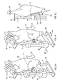
- a slaughtered bird 26 which is hung by its legs from a hook 24 of a conveyor is guided against the support block 6, the forks 12a, 12b being positioned between the hips and the wings of the bird 26.
- the back side of the bird 26 is directed towards the support block 6.
- the bird 26 is at rest with respect to the support block 6 and the associated components; nevertheless, the combination of the bird 26 and the support block 6 with the associated components may be in motion, for example in one of the directions indicated by the double arrow 10. In such a situation, the support block 6 moves synchronously with a movement of the hook 24 in a conveying path.
- Fig. 3 compared to Fig. 2, the support block 6 has been moved downwards along the rods 2, 4 with respect to the hook 24, and the forks 12a and 12b have pivoted away from the body of the bird 26 (i.e. fork 12a has pivoted in the clockwise direction through an angle of approximately 60° about the pin 14a, and fork 12b has pivoted in the counterclockwise direction through an angle of approximately 60° about the pin 14b), and the plate 18 has pivoted through an angle of approximately 25° towards the back of the bird 26, about the axis 20.
- the bird 26 has to a large extent been moved into a predetermined position, in which the forks 12a and 12b clamp the bird 26 in the vertical direction in that they push the elbow joint 28 between the humerus, on the one hand, and the ulna and radius, on the other hand, downwards and outwards.
- a combined sternum support element 30 and clavicle support element 32 is moved into the body cavity of the bird 26 with the aid of a mechanism which is only shown by way of example and is described below.
- the bottom ends of the rods 2 and 4 are connected to one another by means of a bar 34.
- Two substantially L-shaped arms 36 are attached to the bar 34, which arms are connected to one another, in the area of their free ends, by means of a rotatably mounted pin 38, the centre of which is provided with a continuous hole 40.
- two strips 42 are connected, on one side, to the arms 36, in such a manner that they can pivot about respective rotation points 44, and, on the other side, are connected to a wheel carrier 48 which is substantially U-shaped in cross section, in such a manner that they can pivot about respective rotation points 56.
- a rod 50 which is mounted slidably in the hole 40 is fixedly connected to the wheel carrier 48.
- the rod 50 bears the sternum support element 30 as a laterally projecting rod, and the clavicle support element 32 as a rod which projects parallel to the sternum support element 30.
- a spring 56 is situated on the rod 50 between the pin 38 and the wheel carrier 48.
- the wheel carrier 48 is provided with an axle 52 on which a free-running wheel 54 is mounted.
- a rod or strip 66 which, on its underside, may be provided with one or more cutting elements 68 or is shaped in such a manner that a desired cutting action is achieved, in order to be able to move the rod 66 to the desired location.
- the rod 66 acts directly or indirectly on that side of the sternum which is directed towards the abdominal cavity, and pushes it away in a direction directed away from the back of the bird 26.
- Fig. 6a shows the position of the rod 66 in more detail.
- the bird 26 is guided, in the direction of the arrow 10a, past a cutting device comprising a rotating knife 72 which is driven by a motor 70, and a belt 74, which is guided around a roller 76 and is driven, in a manner not shown in more detail, in the direction of arrow 78.
- the belt 74 acts on a breast part 80 which is to be cut off the bird 26, the speed of the belt 74 being at least equal to, or greater than, the speed of movement of the bird 26 in the direction indicated by the arrow 10a.
- FIG. 6a provides a detailed illustration of the location where the belt 74 engages the breast part 80 and of the plane (indicated by a dot-dashed line) along which the knife 72 cuts off the breast part 80.
- the positioning of the bird 26 brought about as shown in Figs. 4 and 5 and the action of the belt 74 make it possible to reproducibly obtain a symmetrical breast part which comprises part of the trabecula mediana and each trabecula intermedia.
- Fig. 1a shows a support block 6a in which the plate 18 as shown in Figs. 1-3 is not present.
- the function of the plate 18 is assumed by a rod 19 which is fixed, in a manner not shown in more detail, with respect to the path of the support block 6a, of which the direction of movement is indicated by arrow 10a.
- the rod 19 has a double bend, the distance between the rod 19 and the rods 2 and 4 to the right of the area 19a being less than the distance between said rods to the left of the area 19a.
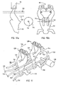
- Figs. 6b, 6c and 6d show an alternative to the rod 50 shown in Fig. 4, with the sternum support element 30 and the clavicle support element 32.
- a rod 50a which is shown in Figs. 6b-6d is provided with a clavicle/sternum support element 32a and a sternum support element 31, the latter being provided with a slot 31a on the side which is facing away from the rod 50a.
- the area which is denoted by 31b comes to rest against the rostrum sterni of the sternum, the spinal-column of the bird moving into the slot 31a of the sternum support element 31.
- the spinal column is pushed away from the sternum as the sternum support element 31 penetrates further into the body of the bird, and consequently the clavicle will move in the same direction. Since in this way it is easier to control the position of the clavicle than in the situation illustrated in Fig. 4, the clavicle/sternum support element 32a in Fig. 6b can be shorter than the clavicle support element 32 in Fig. 4. This reduces the risk of undesired damage to the bird in its neck area.
- Figs. 6e and 6f show a support block 6b which can be moved in directions indicated by double arrow 8 and in a manner which can be controlled and is not shown in more detail, along rods 2 and 4 which extend substantially in the vertical direction.
- the rods 2 and 4 are mounted in plates 3a and 3b, which in turn are fitted in a frame (not shown in more detail).
- a substantially U-shaped bracket 21 with bent ends 21a is mounted on supports 21c in such a manner that it can pivot about pins 21b.
- the bracket 21 can move from the position shown in Fig. 6e to the position shown in Fig. 6f, and vice versa, to which end a suitable controllable drive, which is not shown in more detail, acts on the pins 21b.
- Figs. 6e and 6f show the device in conjunction with a bird carcass which is hung by its legs from a hook.
- Figs. 6g-6j show the device in conjunction with a bird carcass which is hung by its legs from a hook.
- the position of the bracket shown in Fig. 6e will be referred to as “horizontal”
- the position of the bracket 21 shown in Fig. 6f will be referred to as “vertical”.
- Fig. 6g shows a bird 26 hanging from a hook 24.
- Both the hook 24 and the assembly of plates 3a, 3b, rods 2, 4 and support block 6b move synchronously in one of the directions 10, the bird being taken between the ends 21a of the bracket 21 in the horizontal position.
- the support block 6b is moved downwards along the rods 2, 4, until the bracket 21 in the horizontal position is situated at the level of the armpits of the bird 26.
- the bracket 21 is pivoted into its vertical position, the ends 21a of the bracket 21 engaging around the wings of the bird 26.
- the centre part of the bracket 21 pushes against the back of the bird 26. In this way, the bird 26 is excellently positioned and fixed for a following processing operation.
- Figs. 7 and 7a show a section of a wheel 85, which is mounted on a frame (not shown in more detail) and along the circumference of which there are projections 86, the free end of which projections is rounded substantially in the shape of a V, merging into a free end with a predetermined transverse direction.
- the wheel 85 rotates in a direction indicated by arrow 88, the circumferential speed at the foot of the V-shaped free ends of the projections 86 being substantially equal to the conveying speed of a slaughtered bird 92 which is hung by its legs from a hook 90 of a moving conveyor (not shown in more detail).
- the conveying direction of the hook 90 is indicated by arrow 94.
- the legs of the bird are supported against a guide 95 at the level of the drumsticks and on the side facing towards the breast of the bird.
- one of the projections 86 moves between the legs of the bird 92, at the level of its knees. Since the transverse dimensions at the foot of the projection 86 are greater than the distance between the knees of the bird 92, the legs of the bird are spread apart by the projection 86.
- the wheel 85 is mounted on an axle 96, and a guide 98 is arranged beneath each projection 86, in which guide there is a rod 102 which is provided with a transverse arm 100 and can move in its longitudinal direction. At one end, each rod 102 bears a pair of pins 104.
- the guides 98 are arranged in a fixed position with respect to the projections 86 but movably with respect to a stationary cam disc 106 which bears a cam 106a.
- Figs. 10a and 10b show an alternative hip dislocating device, in which, parallel to the path of a conveyor, which is not shown in more detail and moves in the direction of arrow 109, in front of the hooks 90, a set of guides 110 is arranged, in a manner not shown in more detail, in a frame, in order to spread apart the legs of the bird 92, the guides 110 acting in the area of the knees.
- a set of wheels 114 which are mounted on an axle 112 in a frame (not shown in more detail), is situated in the path of the bird 92. The wheels may optionally be rotatable about the axle 112. As the movement in the direction of the arrow 109 continues, the bird 92 at the hook 90 is pulled through between the guides 110 and the wheels 114, the circumferential sides of the wheels 114 dislocating the hips of the bird 92.
- Figs. 11-13 show the essential components of a device for cutting wings off slaughtered birds which are hung by their legs from a hook of a moving conveyor. The elements shown are attached in a frame, which is not shown in more detail for the sake of clarity.
- Figs. 11-13 show four guides 120, 122, 124 and 126 for catching the wings of birds 130 which are hung from hooks 128, and two guides 144, 146 in the transition area between breast and hip. In this case, the right wings 132 are collected between the guides 122 and 126, while the left wings 134 are collected between the guides 120 and 124. Guides 144 and 146 clamp the breast. The birds 130 are moved in the direction of arrow 136.
- a set of rotating knives 142 which are each driven by a motor 138 in the direction of arrow 140, is arranged in the path of the birds 130, in order to cut the wings 132, 134 off the body of the bird 130.
- the shoulder joints of the bird 130 move past the rotating knives 142 in the vicinity of the underside thereof, the active part of the knives 142 moving in the same direction as the shoulder joint.
- Paragraph 1 Method for carrying out at least one processing operation on a slaughtered bird which is hung by its legs, comprising the steps:
- Paragraph 2 Method according to paragraph 1, in which the step of carrying out the at least one processing operation comprises cutting off part of the breast, comprising part of the trabecula mediana and each trabecula intermedia.
- Paragraph 3 Method according to paragraph 2, in which the breast of the bird, while said part of the breast is being cut off, is pushed away substantially parallel to the plane of the cut and in the direction in which the cut is being made.
- Paragraph 4 Method according to any of paragraphs 1-3, in which the step of positioning the bird comprises the step of positioning the clavicle by applying a clavicle support element which acts in the area of the clavicle.
- Paragraph 5 Method according to paragraph 4, in which the clavicle support element engages the clavicle on the concave side of the clavicle.
- Paragraph 6 Method according to any of paragraphs 1-5, in which the step of positioning the bird comprises the step of moving the wings with respect to the body of the bird, substantially in a direction away from the hips of the bird.
- Paragraph 7 Method according to any of paragraphs 1-6, in which each wing of the bird is cut off by means of a rotating knife, the corresponding shoulder joint of the bird moving past the knife in the vicinity of its underside, and the active part of the knife moving substantially in the same direction as the shoulder joint.
- Paragraph 10 Device for carrying out at least one processing operation on a slaughtered bird which is hung by its legs, comprising:
- Paragraph 13 Device according to paragraph 12, in which the back positioning means comprise a pivotable back-support element, at least a part of which is adapted to be brought into contact with the back of the bird.
- Paragraph 14 Device according to paragraph 13, in which the back-support element is a bracket.
- sternum positioning means comprise an arm which can be moved in a controllable manner, one free end of the arm being adapted to act on the side of the sternum facing the abdominal cavity.
- Paragraph 16 Device according to paragraph 15, in which a first part of the arm is pivotably connected to a second part of the arm, and in which the first part can be oriented, in a controllable manner, both substantially in line with the second part and at an angle with respect thereto.
- Paragraph 17 Device according to any of paragraphs 15 ot 16, in which the sternum positioning means are adapted to engage the sternum in the area of the ventricle.
- Paragraph 18 Device according to any of paragraphs 15 or 16, in which the sternum positioning means are adapted to engage the sternum in the area of the rostrum sterni.
- Paragraph 19 Device according to any of paragraphs 9-18, in which the positioning means comprise clavicle positioning means for positioning the clavicle.
- Paragraph 20 Device according to paragraph 19, in which the clavicle positioning means comprise a substantially L-shaped arm which can be moved in a controllable manner and has a short limb and a long limb, the short limb being adapted to engage the concave side of the clavicle.
- Paragraph 21 Device according to any of paragraphs 15-18, in which the clavicle positioning means form a single unit with the sternum positioning means.
- Paragraph 22 Device according to paragraphs 20 or 21, in which the angle between the longitudinal axis of the short limb and a horizontal plane when the short limb is engaging the clavicle is larger than when it is at a distance from the clavicle.
- Paragraph 23 Device according to any of paragraphs 9-22, in which the positioning means comprise a pair of forks which can be moved in a controllable manner in the vertical direction, each with a pair of downwardly directed limbs, the distance between the limbs of each fork substantially corresponding to a transverse dimension of a wing, which forks are adapted each to be placed between the hips and the shoulders of the bird and can pivot, in a controllable manner, between a first angular position, in which the ends of the pairs of limbs have a distance between them which substantially corresponds to the width of the body of a bird between the hips and the shoulders, and a second angular position, in which said ends of said pairs of limbs have a greater distance between them than in the said first angular position.
- the positioning means comprise a pair of forks which can be moved in a controllable manner in the vertical direction, each with a pair of downwardly directed limbs, the distance between the limbs of each fork substantially
- Paragraph 24 Device according to paragraph 23, in which the forks are arranged on a common support body.
- Paragraph 25 Device according to paragraphs 12 and 23, or 13 and 24, in which the back positioning means are arranged on said common support body.
- Paragraph 26 Device according to any of paragraphs 9-25, comprising:
Landscapes
- Life Sciences & Earth Sciences (AREA)
- Engineering & Computer Science (AREA)
- Wood Science & Technology (AREA)
- Zoology (AREA)
- Food Science & Technology (AREA)
- Processing Of Meat And Fish (AREA)
- Housing For Livestock And Birds (AREA)
Applications Claiming Priority (2)
| Application Number | Priority Date | Filing Date | Title |
|---|---|---|---|
| NL1009670A NL1009670C2 (nl) | 1998-07-16 | 1998-07-16 | Werkwijze en inrichting voor het bewerken van gevogelte. |
| EP99931602A EP1096860B1 (de) | 1998-07-16 | 1999-07-07 | Verfahren und vorrichtung zur bearbeitung von schlachtgeflügel |
Related Parent Applications (1)
| Application Number | Title | Priority Date | Filing Date |
|---|---|---|---|
| EP99931602A Division EP1096860B1 (de) | 1998-07-16 | 1999-07-07 | Verfahren und vorrichtung zur bearbeitung von schlachtgeflügel |
Publications (2)
| Publication Number | Publication Date |
|---|---|
| EP1665936A1 true EP1665936A1 (de) | 2006-06-07 |
| EP1665936B1 EP1665936B1 (de) | 2014-06-11 |
Family
ID=19767508
Family Applications (2)
| Application Number | Title | Priority Date | Filing Date |
|---|---|---|---|
| EP99931602A Expired - Lifetime EP1096860B1 (de) | 1998-07-16 | 1999-07-07 | Verfahren und vorrichtung zur bearbeitung von schlachtgeflügel |
| EP06075285.4A Expired - Lifetime EP1665936B1 (de) | 1998-07-16 | 1999-07-07 | Verfahren und Vorrichtung zur Bearbeitung von Schlachtgeflügel |
Family Applications Before (1)
| Application Number | Title | Priority Date | Filing Date |
|---|---|---|---|
| EP99931602A Expired - Lifetime EP1096860B1 (de) | 1998-07-16 | 1999-07-07 | Verfahren und vorrichtung zur bearbeitung von schlachtgeflügel |
Country Status (9)
| Country | Link |
|---|---|
| US (1) | US6450873B2 (de) |
| EP (2) | EP1096860B1 (de) |
| JP (1) | JP2002520035A (de) |
| AT (1) | ATE319317T1 (de) |
| DE (1) | DE69930263T2 (de) |
| DK (1) | DK1096860T3 (de) |
| ES (1) | ES2259836T3 (de) |
| NL (1) | NL1009670C2 (de) |
| WO (1) | WO2000003604A1 (de) |
Cited By (3)
| Publication number | Priority date | Publication date | Assignee | Title |
|---|---|---|---|---|
| NL2000159C2 (nl) * | 2006-07-24 | 2008-01-25 | Stork Pmt | Inrichting, werkwijze en productielijn voor het conditioneren van geslacht pluimvee. |
| CN104286132A (zh) * | 2014-08-08 | 2015-01-21 | 广东羽威农业集团有限公司 | 水禽自动化加工流水线及加工方法 |
| CN111587908A (zh) * | 2020-05-09 | 2020-08-28 | 安徽省争华食品有限公司 | 一种羊骨架分割夹具 |
Families Citing this family (13)
| Publication number | Priority date | Publication date | Assignee | Title |
|---|---|---|---|---|
| US7004830B2 (en) | 1998-07-16 | 2006-02-28 | Stork Pmt B.V. | Method and device for processing poultry |
| DK2258202T3 (en) * | 2002-12-20 | 2015-03-02 | Marel Stork Poultry Proc Bv | Method and device for working a body part of slaughtered poultry |
| US8613959B2 (en) | 2009-02-10 | 2013-12-24 | Fhg Corporation | Dietary supplements containing extracts of Nelumbo and processes of using same |
| NL2002992C2 (en) * | 2009-06-10 | 2010-12-13 | Foodmate B V | Method and apparatus for automatic meat processing. |
| CA2778719C (en) * | 2009-10-23 | 2013-11-19 | Centre De Recherche Industrielle Du Quebec | System and method for trussing slaughtered birds |
| NL2014197B1 (en) | 2015-01-27 | 2017-01-06 | Foodmate Bv | Device for making a preparatory incision longitudinally of an animal extremity part with first and second bones articulated by a joint. |
| CN106962449B (zh) * | 2017-05-26 | 2023-05-05 | 安阳沃艾纳智能科技有限公司 | 肉鸡屠宰生产中的自动挂鸡系统 |
| NL2023211B1 (en) | 2019-05-27 | 2020-12-02 | Meyn Food Processing Tech Bv | An apparatus for carrying out an operation on slaughtered poultry or on a part of slaughtered poultry |
| NL2024085B1 (en) * | 2019-10-23 | 2021-07-13 | Meyn Food Processing Tech Bv | Deskinning apparatus and method for deskinning a poultry leg or part of a poultry leg |
| CN110973218A (zh) * | 2019-12-26 | 2020-04-10 | 无为县马玉虎板鸭店 | 一种制作板鸭用的鸭子解剖台 |
| CN112189704A (zh) * | 2020-09-11 | 2021-01-08 | 岳昌顺 | 一种基于非牛顿流体防挣脱的禽类倒悬宰杀辅助装置 |
| WO2023010185A1 (pt) * | 2021-08-04 | 2023-02-09 | Da Silva Choai Orlei | Equipamento e método para pendurar aves e similares |
| KR102839937B1 (ko) * | 2024-02-06 | 2025-07-31 | (주)로보스 | 도체 유동방지 컨베이어 시스템 |
Citations (8)
| Publication number | Priority date | Publication date | Assignee | Title |
|---|---|---|---|---|
| EP0033177B1 (de) | 1980-01-23 | 1983-06-29 | Tieleman B.V. | Vorrichtung zum Durchschneiden von geschlachtetem Geflügel in separate Stücke |
| NL8400170A (nl) * | 1984-01-18 | 1985-08-16 | Meyn Pieter | Inrichting voor het afsnijden van een gedeelte van geslacht gevogelte. |
| US4964194A (en) * | 1989-04-24 | 1990-10-23 | L. J. Kessler | Apparatus and method for disjointing the thighbones of poultry carcasses |
| EP0395169A2 (de) * | 1989-04-24 | 1990-10-31 | Linco Holland Engineering B.V. | Verfahren und Vorrichtung zum Abtrennen der Beine von Schlachtgeflügel |
| US5147240A (en) * | 1992-01-23 | 1992-09-15 | Hazenbroek Jacobus E | Thigh joint separator and carcass halving apparatus |
| US5188559A (en) * | 1991-09-16 | 1993-02-23 | Hazenbroek Jacobus E | Method and apparatus for separating the legs from the back of a poultry carcass |
| EP0545040A1 (de) | 1991-12-02 | 1993-06-09 | Jacobus E. Hazenbroek | Vorrichtung zum Entfernen von Geflügelbrust und -fett |
| EP0562661A1 (de) | 1992-03-24 | 1993-09-29 | Machinefabriek Meyn B.V. | Vorrichtung zum Halten von Schlachtgeflügel |
Family Cites Families (9)
| Publication number | Priority date | Publication date | Assignee | Title |
|---|---|---|---|---|
| US3958303A (en) * | 1974-12-16 | 1976-05-25 | Gordon Johnson Company | Method and apparatus for poultry vent removal |
| NL188449C (nl) * | 1984-01-18 | 1992-07-01 | Systemate Bv | Vleugelsnijder. |
| US4669148A (en) * | 1985-01-23 | 1987-06-02 | Simon-Johnson, Inc. | Machine for cutting up poultry into a number of pieces |
| NL8602922A (nl) * | 1986-11-18 | 1988-06-16 | Systemate Bv | Machine voor het delen van gevogelte. |
| FR2624695B1 (fr) * | 1987-12-18 | 1992-01-24 | Servajean Roger | Dispositif pour le maintien et l'accrochage des volailles dans les machines d'evisceration notamment |
| NL8901340A (nl) * | 1989-05-29 | 1990-12-17 | Meyn Maschf | Inrichting voor het uitvoeren van een bewerking op het inwendige van geslacht gevogelte. |
| US5429549A (en) * | 1994-10-05 | 1995-07-04 | Systemate Holland, B.V. | Sequential wing remover |
| US5569072A (en) * | 1996-01-19 | 1996-10-29 | Johnson Food Equipment, Inc. | Poultry processing mechanism having carcass stabilizer |
| DE69721387T2 (de) * | 1996-01-19 | 2003-12-11 | Johnson Food Equipment, Inc. | Verfahren und vorrichtung zum entnehmen von geflügel einschliesslich kropfes |
-
1998
- 1998-07-16 NL NL1009670A patent/NL1009670C2/nl not_active IP Right Cessation
-
1999
- 1999-07-07 EP EP99931602A patent/EP1096860B1/de not_active Expired - Lifetime
- 1999-07-07 DE DE69930263T patent/DE69930263T2/de not_active Expired - Fee Related
- 1999-07-07 JP JP2000559748A patent/JP2002520035A/ja active Pending
- 1999-07-07 EP EP06075285.4A patent/EP1665936B1/de not_active Expired - Lifetime
- 1999-07-07 ES ES99931602T patent/ES2259836T3/es not_active Expired - Lifetime
- 1999-07-07 AT AT99931602T patent/ATE319317T1/de not_active IP Right Cessation
- 1999-07-07 WO PCT/NL1999/000432 patent/WO2000003604A1/en not_active Ceased
- 1999-07-07 DK DK99931602T patent/DK1096860T3/da active
-
2001
- 2001-01-16 US US09/761,567 patent/US6450873B2/en not_active Expired - Fee Related
Patent Citations (8)
| Publication number | Priority date | Publication date | Assignee | Title |
|---|---|---|---|---|
| EP0033177B1 (de) | 1980-01-23 | 1983-06-29 | Tieleman B.V. | Vorrichtung zum Durchschneiden von geschlachtetem Geflügel in separate Stücke |
| NL8400170A (nl) * | 1984-01-18 | 1985-08-16 | Meyn Pieter | Inrichting voor het afsnijden van een gedeelte van geslacht gevogelte. |
| US4964194A (en) * | 1989-04-24 | 1990-10-23 | L. J. Kessler | Apparatus and method for disjointing the thighbones of poultry carcasses |
| EP0395169A2 (de) * | 1989-04-24 | 1990-10-31 | Linco Holland Engineering B.V. | Verfahren und Vorrichtung zum Abtrennen der Beine von Schlachtgeflügel |
| US5188559A (en) * | 1991-09-16 | 1993-02-23 | Hazenbroek Jacobus E | Method and apparatus for separating the legs from the back of a poultry carcass |
| EP0545040A1 (de) | 1991-12-02 | 1993-06-09 | Jacobus E. Hazenbroek | Vorrichtung zum Entfernen von Geflügelbrust und -fett |
| US5147240A (en) * | 1992-01-23 | 1992-09-15 | Hazenbroek Jacobus E | Thigh joint separator and carcass halving apparatus |
| EP0562661A1 (de) | 1992-03-24 | 1993-09-29 | Machinefabriek Meyn B.V. | Vorrichtung zum Halten von Schlachtgeflügel |
Cited By (6)
| Publication number | Priority date | Publication date | Assignee | Title |
|---|---|---|---|---|
| NL2000159C2 (nl) * | 2006-07-24 | 2008-01-25 | Stork Pmt | Inrichting, werkwijze en productielijn voor het conditioneren van geslacht pluimvee. |
| WO2008013446A1 (en) * | 2006-07-24 | 2008-01-31 | Stork Pmt B.V. | Device and method for conditioning slaughtered poultry and production line for processing poultry carcasses |
| US8105138B2 (en) | 2006-07-24 | 2012-01-31 | Marel Stork Poultry Processing B.V. | Device and method for conditioning slaughtered poultry and production line for processing poultry carcasses |
| CN104286132A (zh) * | 2014-08-08 | 2015-01-21 | 广东羽威农业集团有限公司 | 水禽自动化加工流水线及加工方法 |
| CN104286132B (zh) * | 2014-08-08 | 2019-08-30 | 广东羽威农业集团有限公司 | 水禽自动化加工流水线及加工方法 |
| CN111587908A (zh) * | 2020-05-09 | 2020-08-28 | 安徽省争华食品有限公司 | 一种羊骨架分割夹具 |
Also Published As
| Publication number | Publication date |
|---|---|
| EP1096860B1 (de) | 2006-03-08 |
| DE69930263D1 (de) | 2006-05-04 |
| DE69930263T2 (de) | 2006-12-28 |
| WO2000003604A1 (en) | 2000-01-27 |
| EP1665936B1 (de) | 2014-06-11 |
| DK1096860T3 (da) | 2006-07-17 |
| ATE319317T1 (de) | 2006-03-15 |
| ES2259836T3 (es) | 2006-10-16 |
| EP1096860A1 (de) | 2001-05-09 |
| NL1009670C2 (nl) | 2000-01-18 |
| JP2002520035A (ja) | 2002-07-09 |
| US6450873B2 (en) | 2002-09-17 |
| US20010014580A1 (en) | 2001-08-16 |
Similar Documents
| Publication | Publication Date | Title |
|---|---|---|
| EP1665936B1 (de) | Verfahren und Vorrichtung zur Bearbeitung von Schlachtgeflügel | |
| US5173077A (en) | Method and device for performing an accurate cutting operation near the knee joint of a leg of a slaughtered animal | |
| US7004830B2 (en) | Method and device for processing poultry | |
| US5147240A (en) | Thigh joint separator and carcass halving apparatus | |
| EP1164857B1 (de) | Verfahren und vorrichtung zum bearbeiten von geflügelbeinen | |
| EP0590733B1 (de) | Verfahren und Vorrichtung zum Entbeinen von Beinstücken von Schlachttieren | |
| US5015213A (en) | On-line cut-up system with joint opener | |
| JPH09103231A (ja) | 屠殺獣の処理装置及び処理方法 | |
| KR102166227B1 (ko) | 동물 사지로부터 고기를 자동으로 제거하기 위한 방법 및 시스템 | |
| US5176562A (en) | Dark meat deboner with leg scraper | |
| US6277020B1 (en) | Method and apparatus for removing meat from poultry carcasses | |
| JP2010512784A (ja) | 解体処理された家禽の胴体部分から背皮と背肉とを別々に採取するための方法および装置 | |
| US5466185A (en) | Removing breast meat from poultry | |
| US5569069A (en) | Apparatus for cutting wings from poultry | |
| EP0369544B1 (de) | Vorrichtung zum Abtrennen der Beine von Schlachtgeflügel-Rückenstücken | |
| US5102369A (en) | Dark meat deboner | |
| KR20150046086A (ko) | 새를 족쇄에 매다는 방법 및 새들을 매다는 장치 | |
| JPH0523100A (ja) | ブレストプロセツサー | |
| PT93408A (pt) | Processo e dispositivo para o corte de aves | |
| GB2117224A (en) | Method of, and apparatus for, leg severing | |
| EP3367805B1 (de) | Verfahren, führungsanordnung und system zum trennen von aus geschlachtetem geflügel ausgeweideten eingeweidesätzen | |
| WO2025123078A1 (en) | Apparatus and method of removing flesh from poultry | |
| CN115361873A (zh) | 用于安置家禽屠体的背部或其部分的保持元件 |
Legal Events
| Date | Code | Title | Description |
|---|---|---|---|
| PUAI | Public reference made under article 153(3) epc to a published international application that has entered the european phase |
Free format text: ORIGINAL CODE: 0009012 |
|
| AC | Divisional application: reference to earlier application |
Ref document number: 1096860 Country of ref document: EP Kind code of ref document: P |
|
| AK | Designated contracting states |
Kind code of ref document: A1 Designated state(s): AT BE CH CY DE DK ES FI FR GB GR IE IT LI LU MC NL PT SE |
|
| 17P | Request for examination filed |
Effective date: 20061019 |
|
| AKX | Designation fees paid |
Designated state(s): AT BE CH CY DE DK ES FI FR GB GR IE IT LI LU MC NL PT SE |
|
| RAP1 | Party data changed (applicant data changed or rights of an application transferred) |
Owner name: MAREL STORK POULTRY PROCESSING B.V. |
|
| 17Q | First examination report despatched |
Effective date: 20110531 |
|
| GRAP | Despatch of communication of intention to grant a patent |
Free format text: ORIGINAL CODE: EPIDOSNIGR1 |
|
| INTG | Intention to grant announced |
Effective date: 20140206 |
|
| GRAS | Grant fee paid |
Free format text: ORIGINAL CODE: EPIDOSNIGR3 |
|
| GRAA | (expected) grant |
Free format text: ORIGINAL CODE: 0009210 |
|
| AC | Divisional application: reference to earlier application |
Ref document number: 1096860 Country of ref document: EP Kind code of ref document: P |
|
| AK | Designated contracting states |
Kind code of ref document: B1 Designated state(s): AT BE CH CY DE DK ES FI FR GB GR IE IT LI LU MC NL PT SE |
|
| REG | Reference to a national code |
Ref country code: GB Ref legal event code: FG4D |
|
| REG | Reference to a national code |
Ref country code: CH Ref legal event code: EP |
|
| REG | Reference to a national code |
Ref country code: IE Ref legal event code: FG4D |
|
| REG | Reference to a national code |
Ref country code: AT Ref legal event code: REF Ref document number: 671743 Country of ref document: AT Kind code of ref document: T Effective date: 20140715 |
|
| REG | Reference to a national code |
Ref country code: DE Ref legal event code: R096 Ref document number: 69945116 Country of ref document: DE Effective date: 20140724 |
|
| PG25 | Lapsed in a contracting state [announced via postgrant information from national office to epo] |
Ref country code: FI Free format text: LAPSE BECAUSE OF FAILURE TO SUBMIT A TRANSLATION OF THE DESCRIPTION OR TO PAY THE FEE WITHIN THE PRESCRIBED TIME-LIMIT Effective date: 20140611 Ref country code: GR Free format text: LAPSE BECAUSE OF FAILURE TO SUBMIT A TRANSLATION OF THE DESCRIPTION OR TO PAY THE FEE WITHIN THE PRESCRIBED TIME-LIMIT Effective date: 20140912 |
|
| REG | Reference to a national code |
Ref country code: NL Ref legal event code: VDEP Effective date: 20140611 |
|
| REG | Reference to a national code |
Ref country code: AT Ref legal event code: MK05 Ref document number: 671743 Country of ref document: AT Kind code of ref document: T Effective date: 20140611 |
|
| PG25 | Lapsed in a contracting state [announced via postgrant information from national office to epo] |
Ref country code: SE Free format text: LAPSE BECAUSE OF FAILURE TO SUBMIT A TRANSLATION OF THE DESCRIPTION OR TO PAY THE FEE WITHIN THE PRESCRIBED TIME-LIMIT Effective date: 20140611 |
|
| PG25 | Lapsed in a contracting state [announced via postgrant information from national office to epo] |
Ref country code: ES Free format text: LAPSE BECAUSE OF FAILURE TO SUBMIT A TRANSLATION OF THE DESCRIPTION OR TO PAY THE FEE WITHIN THE PRESCRIBED TIME-LIMIT Effective date: 20140611 Ref country code: PT Free format text: LAPSE BECAUSE OF FAILURE TO SUBMIT A TRANSLATION OF THE DESCRIPTION OR TO PAY THE FEE WITHIN THE PRESCRIBED TIME-LIMIT Effective date: 20141013 |
|
| REG | Reference to a national code |
Ref country code: DE Ref legal event code: R119 Ref document number: 69945116 Country of ref document: DE |
|
| PG25 | Lapsed in a contracting state [announced via postgrant information from national office to epo] |
Ref country code: NL Free format text: LAPSE BECAUSE OF FAILURE TO SUBMIT A TRANSLATION OF THE DESCRIPTION OR TO PAY THE FEE WITHIN THE PRESCRIBED TIME-LIMIT Effective date: 20140611 Ref country code: AT Free format text: LAPSE BECAUSE OF FAILURE TO SUBMIT A TRANSLATION OF THE DESCRIPTION OR TO PAY THE FEE WITHIN THE PRESCRIBED TIME-LIMIT Effective date: 20140611 |
|
| REG | Reference to a national code |
Ref country code: CH Ref legal event code: PL |
|
| PG25 | Lapsed in a contracting state [announced via postgrant information from national office to epo] |
Ref country code: MC Free format text: LAPSE BECAUSE OF FAILURE TO SUBMIT A TRANSLATION OF THE DESCRIPTION OR TO PAY THE FEE WITHIN THE PRESCRIBED TIME-LIMIT Effective date: 20140611 |
|
| PLBE | No opposition filed within time limit |
Free format text: ORIGINAL CODE: 0009261 |
|
| STAA | Information on the status of an ep patent application or granted ep patent |
Free format text: STATUS: NO OPPOSITION FILED WITHIN TIME LIMIT |
|
| REG | Reference to a national code |
Ref country code: IE Ref legal event code: MM4A |
|
| REG | Reference to a national code |
Ref country code: FR Ref legal event code: ST Effective date: 20150331 |
|
| PG25 | Lapsed in a contracting state [announced via postgrant information from national office to epo] |
Ref country code: CH Free format text: LAPSE BECAUSE OF NON-PAYMENT OF DUE FEES Effective date: 20140731 Ref country code: LI Free format text: LAPSE BECAUSE OF NON-PAYMENT OF DUE FEES Effective date: 20140731 Ref country code: DE Free format text: LAPSE BECAUSE OF NON-PAYMENT OF DUE FEES Effective date: 20150203 Ref country code: IT Free format text: LAPSE BECAUSE OF FAILURE TO SUBMIT A TRANSLATION OF THE DESCRIPTION OR TO PAY THE FEE WITHIN THE PRESCRIBED TIME-LIMIT Effective date: 20140611 Ref country code: DK Free format text: LAPSE BECAUSE OF FAILURE TO SUBMIT A TRANSLATION OF THE DESCRIPTION OR TO PAY THE FEE WITHIN THE PRESCRIBED TIME-LIMIT Effective date: 20140611 |
|
| 26N | No opposition filed |
Effective date: 20150312 |
|
| REG | Reference to a national code |
Ref country code: DE Ref legal event code: R119 Ref document number: 69945116 Country of ref document: DE Effective date: 20150203 |
|
| GBPC | Gb: european patent ceased through non-payment of renewal fee |
Effective date: 20140911 |
|
| PG25 | Lapsed in a contracting state [announced via postgrant information from national office to epo] |
Ref country code: FR Free format text: LAPSE BECAUSE OF NON-PAYMENT OF DUE FEES Effective date: 20140811 |
|
| PG25 | Lapsed in a contracting state [announced via postgrant information from national office to epo] |
Ref country code: BE Free format text: LAPSE BECAUSE OF FAILURE TO SUBMIT A TRANSLATION OF THE DESCRIPTION OR TO PAY THE FEE WITHIN THE PRESCRIBED TIME-LIMIT Effective date: 20140611 |
|
| PG25 | Lapsed in a contracting state [announced via postgrant information from national office to epo] |
Ref country code: GB Free format text: LAPSE BECAUSE OF NON-PAYMENT OF DUE FEES Effective date: 20140911 |
|
| PG25 | Lapsed in a contracting state [announced via postgrant information from national office to epo] |
Ref country code: IE Free format text: LAPSE BECAUSE OF NON-PAYMENT OF DUE FEES Effective date: 20140707 |
|
| PG25 | Lapsed in a contracting state [announced via postgrant information from national office to epo] |
Ref country code: CY Free format text: LAPSE BECAUSE OF FAILURE TO SUBMIT A TRANSLATION OF THE DESCRIPTION OR TO PAY THE FEE WITHIN THE PRESCRIBED TIME-LIMIT Effective date: 20140611 |
|
| PG25 | Lapsed in a contracting state [announced via postgrant information from national office to epo] |
Ref country code: LU Free format text: LAPSE BECAUSE OF NON-PAYMENT OF DUE FEES Effective date: 20140707 |