EP1666018A1 - Récipient pour la préparation électrique de fluides injectables - Google Patents
Récipient pour la préparation électrique de fluides injectables Download PDFInfo
- Publication number
- EP1666018A1 EP1666018A1 EP06002913A EP06002913A EP1666018A1 EP 1666018 A1 EP1666018 A1 EP 1666018A1 EP 06002913 A EP06002913 A EP 06002913A EP 06002913 A EP06002913 A EP 06002913A EP 1666018 A1 EP1666018 A1 EP 1666018A1
- Authority
- EP
- European Patent Office
- Prior art keywords
- container
- reservoir
- electrodes
- substance
- electrode
- Prior art date
- Legal status (The legal status is an assumption and is not a legal conclusion. Google has not performed a legal analysis and makes no representation as to the accuracy of the status listed.)
- Withdrawn
Links
- 239000000126 substance Substances 0.000 title claims description 27
- 239000012530 fluid Substances 0.000 claims description 38
- 238000000034 method Methods 0.000 claims description 16
- 238000007789 sealing Methods 0.000 claims description 7
- 238000011109 contamination Methods 0.000 claims description 6
- 238000004891 communication Methods 0.000 claims description 4
- 238000001990 intravenous administration Methods 0.000 claims description 4
- 239000000463 material Substances 0.000 claims description 4
- 230000007246 mechanism Effects 0.000 claims description 4
- 238000012546 transfer Methods 0.000 claims description 3
- 239000007788 liquid Substances 0.000 claims description 2
- 239000003814 drug Substances 0.000 claims 1
- 230000035515 penetration Effects 0.000 claims 1
- 230000008878 coupling Effects 0.000 abstract description 2
- 238000010168 coupling process Methods 0.000 abstract description 2
- 238000005859 coupling reaction Methods 0.000 abstract description 2
- 230000008901 benefit Effects 0.000 description 7
- 238000010276 construction Methods 0.000 description 7
- 238000002347 injection Methods 0.000 description 7
- 239000007924 injection Substances 0.000 description 7
- 230000004888 barrier function Effects 0.000 description 5
- 229910052751 metal Inorganic materials 0.000 description 3
- 239000002184 metal Substances 0.000 description 3
- 230000008569 process Effects 0.000 description 3
- 230000001225 therapeutic effect Effects 0.000 description 3
- 239000004020 conductor Substances 0.000 description 2
- 238000013461 design Methods 0.000 description 2
- 239000011888 foil Substances 0.000 description 2
- 125000000391 vinyl group Chemical group [H]C([*])=C([H])[H] 0.000 description 2
- 229920002554 vinyl polymer Polymers 0.000 description 2
- 206010067484 Adverse reaction Diseases 0.000 description 1
- 241000124008 Mammalia Species 0.000 description 1
- RTAQQCXQSZGOHL-UHFFFAOYSA-N Titanium Chemical compound [Ti] RTAQQCXQSZGOHL-UHFFFAOYSA-N 0.000 description 1
- 230000003213 activating effect Effects 0.000 description 1
- 230000006838 adverse reaction Effects 0.000 description 1
- 230000003466 anti-cipated effect Effects 0.000 description 1
- 238000001815 biotherapy Methods 0.000 description 1
- 230000000694 effects Effects 0.000 description 1
- 239000002659 electrodeposit Substances 0.000 description 1
- 238000009713 electroplating Methods 0.000 description 1
- PCHJSUWPFVWCPO-UHFFFAOYSA-N gold Chemical compound [Au] PCHJSUWPFVWCPO-UHFFFAOYSA-N 0.000 description 1
- 229910052737 gold Inorganic materials 0.000 description 1
- 239000010931 gold Substances 0.000 description 1
- 230000005484 gravity Effects 0.000 description 1
- 230000036512 infertility Effects 0.000 description 1
- 238000004519 manufacturing process Methods 0.000 description 1
- 150000002739 metals Chemical class 0.000 description 1
- 239000000203 mixture Substances 0.000 description 1
- 238000012986 modification Methods 0.000 description 1
- 230000004048 modification Effects 0.000 description 1
- 230000001151 other effect Effects 0.000 description 1
- 239000013618 particulate matter Substances 0.000 description 1
- 238000002360 preparation method Methods 0.000 description 1
- 238000000926 separation method Methods 0.000 description 1
- 238000004513 sizing Methods 0.000 description 1
- 239000000758 substrate Substances 0.000 description 1
- 239000010936 titanium Substances 0.000 description 1
- 229910052719 titanium Inorganic materials 0.000 description 1
Images


Classifications
-
- A—HUMAN NECESSITIES
- A61—MEDICAL OR VETERINARY SCIENCE; HYGIENE
- A61K—PREPARATIONS FOR MEDICAL, DENTAL OR TOILETRY PURPOSES
- A61K41/00—Medicinal preparations obtained by treating materials with wave energy or particle radiation ; Therapies using these preparations
- A61K41/0004—Homeopathy; Vitalisation; Resonance; Dynamisation, e.g. esoteric applications; Oxygenation of blood
-
- A—HUMAN NECESSITIES
- A61—MEDICAL OR VETERINARY SCIENCE; HYGIENE
- A61J—CONTAINERS SPECIALLY ADAPTED FOR MEDICAL OR PHARMACEUTICAL PURPOSES; DEVICES OR METHODS SPECIALLY ADAPTED FOR BRINGING PHARMACEUTICAL PRODUCTS INTO PARTICULAR PHYSICAL OR ADMINISTERING FORMS; DEVICES FOR ADMINISTERING FOOD OR MEDICINES ORALLY; BABY COMFORTERS; DEVICES FOR RECEIVING SPITTLE
- A61J1/00—Containers specially adapted for medical or pharmaceutical purposes
- A61J1/14—Details; Accessories therefor
- A61J1/1406—Septums, pierceable membranes
Definitions
- the present invention generally relates to devices used to prepare therapeutic substances. More specifically, the present invention relates to devices used to prepare and dispense electrically-activated therapeutic substances.
- One type of biotherapy generally uses an electrolytic fluid that is treated with electrical currents prior to use.
- the fluid is injected into the recipient.
- the application of the electrical current to the fluid generally is done with a power supply and a signal generator.
- the electrical current is designed to trigger or enhance the therapeutic effectiveness of the electrolytic fluid or it's components.
- the electrolytic fluid is placed in a beaker, which holds the fluid and two or more electrodes.
- a signal generator passes an electrical current through the fluid between the electrodes to condition the fluid. After application of the current, the fluid is filtered and sterilized as needed before being placed in a syringe for injection into the patient.
- the patient is usually a human or mammal.
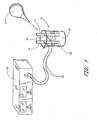
- the beaker 10 includes a reservoir area 12 for fluids, a set of electrodes 14 that extend into the reservoir area 12 and an opening area 16. Fluids 18 may be placed in the container 10 and an electric current can be applied to the fluids 18 through a set of wires 20 and the corresponding electrodes 14. The current can be supplied by a signal generator 22.
- a utensil 24 such as a syringe, a tube, a squeeze bulb, a pipette, or any other suitable utensil, can be used to remove the electrically prepared fluid from the container 10. The fluid then is prepared for injection.
- This process for preparing the active fluid has several disadvantages.
- One disadvantage is that the fluid must be handled quite a bit, such as when it is transferred between generally open containers to prepare it for use and to prepare it for administration. Additionally, the electrodes and the activating container must be cleaned and sterilized before each use, which activities are time consuming and require specialized equipment.
- a container has been developed for preparing and administering electrically prepared substances used by injection without requiring a transfer of the substances from one container to another container.
- One aspect of the present invention involves a container adapted to hold a fluid substance.
- the container comprises at least one wall and a reservoir defined at least in part by the wall.
- At least two electrically conductive members extend into the reservoir.
- the electrically conductive members do not contact one another within the reservoir.
- the electrically conductive members are in electrical communication with respective contact elements disposed outside of said reservoir.
- a sealing portion cooperates with the outside surface to enclose the reservoir.
- Another aspect of the present invention involves a method of preparing an electrically-activated injectable grade substance.
- the method comprises providing a container with a reservoir and at least one electrode extending into the container, at least partially filling the reservoir with an injectable grade substance, sealing the electrode and the substance in the reservoir, and applying an electrical signal to the electrode.
- a further aspect of the present invention involves a flexible container adapted to hold a fluid.
- the container comprises a flexible wall that at least partially defines a reservoir. At least two electrically conductive electrodes are disposed at least partially in the reservoir. A gap is defined between the electrodes and the electrodes each have a portion exposed outside of the container when the container is closed.
- the illustrated container 30 comprises a vial-type of container.
- the container 30 is a relatively small size.
- the container 30 is designed to hold between about 1 milliliter and 1 liter of fluid.
- the container 30 is of a standard vial size and proportion such that the container 30 can be handled with exiting automated filling and assembly equipment.
- the container 30 is sized to accommodate a single dosage of electrically-prepared fluid.
- a reservoir area 32 is defined within the container 30.
- the container 30 accommodates any suitable fluids 34 and the reservoir 32 can be closed with a lid 36.
- a seal 38 preferably is interposed between a portion of the lid 36 and a portion of the container 30.
- the seal can be arranged in the manner described in my co-pending application entitled Vial With Vent Design, which was filed on the same date as this disclosure, which is hereby expressly incorporated by reference.
- the lid 36 desirably is tightly sealed to the container 30 and is configured to resist opening.
- the lid 36 is designed to provide evidence of tampering after the lid 36 is secured to the container 30.
- the sealing construction, the tamper resistant construction and the tamper evidencing construction can be of any suitable configuration and many such constructions are well known.
- electrically conductive electrodes 40 preferably are at least partially disposed within the reservoir area 32.
- the electrodes 40 are directly secured to an inner surface of the container 30.
- the electrodes 40 are positioned such that they are in direct contact with at least a portion of the fluid 34 disposed within the container 30. While the illustrated electrodes 40 are placed on the sides of the container 30, the electrodes 40 can be placed on the ends of the container, wound in a circular or mounted in any other fashion while maintaining contact with the fluid 34 disposed within the container 30. In some arrangements, the electrodes 40 can be centrally disposed within the reservoir area 32.
- the electrodes 40 can be positioned on opposing inner surfaces of the container 30. In is anticipated that the electrodes 40 can be placed in any number of different locations in the container 40. By positioning the electrodes 40 on opposing inner surfaces of the container 30, the separation of the electrodes 40 can be maximized. Of course, if-a non-round container is used, the electrodes 40 can be positioned is the corners, on opposing surfaces or in any other suitable location.
- the electrodes 40 preferably extend outside of the reservoir area 32. In one arrangement, the electrodes 40 do not extend outside of the reservoir area 32 but are in electrical communication with connectors that are positioned outside of the sealed container 30. In another arrangement, the container 30 can be configured with only one electrode 40. With one electrode 40, the container 30 may be formed from an electrically conductive material or may comprise an electrically conductive member with the whole container 30 forming an electrode 40. In such a case, the signal generator that connects to the electrode 40 may be set to supply radio-frequency electrical signals to condition the substance in the container 30. In another arrangement, the electrode 40 can be configured so that the container 30 may comprise an electrically conductive material to form the first electrode 40 and an insulating portion and a second electrode 40 can be positioned inside the container 30. The electric current then flows from the electrode 40 inside the container 30, through the contents of the container 30 and to the conductive portion of the container 30.
- the electrodes 40 preferably are formed of gold, titanium or other suitable metals or conductive elements.
- the electrodes 40 can be formed with electrodeposits of vapors, by electroplating, with metal foil tape or by any other suitable techniques.
- the electrodes 40 are thin enough to not interfere with the seal 38 that is disposed between the lid 36 and the container 30.
- the electrodes 40 can be enlarged if an electrical connection can be established in other methods.
- the electrodes 40 can extend through at least a portion of the lid 36. In one presently preferred arrangement, the electrodes 40 generally are about 44 mm wide and about .30 mm thick.
- the exact sizing and configuration of the electrodes 40 can vary; however, the electrodes 40 preferably have a resistance below approximately 5000 ohms per square centimeter, and insulating portions disposed between the electrodes 40 should provide approximately 100 ohms or more resistance between the electrodes 40 to avoid shorting away excessive current.
- the seal 38 is configured in such a manner to provide a substantially contamination resistant seal between the contents of the container 30 and the exterior of the container 30.
- the electrodes 40 extend from the interior of the container 30, past the seal 38 to the outside of the container 30, where clip leads or other suitable electrical connections may be made.
- the container 30 can be filled under controlled conditions using suitable processes.
- the container 30 is filled with a sterile, injectable fluid 34 prior to the lid 36 being secured in position on the container 30.
- the processes advantageously produce a filled container 30 that has sterilized and relatively particulate free contents. In some applications, it is particularly important that the container 30 be free of even sterile particulate matter, in order to avoid an adverse reaction in the patient.
- a current can be applied to the container 30.
- a signal generator 42 is used to supply the current.
- Various types of electrical signal generators 42 may be used to provide the electric signals.
- Genetronics, Inc., of San Diego, CA makes several bioelectric signal-generating apparatuses that can be used, for instance.
- the current preferably is applied for a preset period of time before any activated fluid 34 is withdrawn from the container 30.
- the current travels from one wire 44 of the signal generator 42 to a clip (not shown). At the clip, the current is transferred to an exterior portion of one electrode 40.
- a clip not shown
- other electrical connections can result in the current passing through an intermediate member before passing to the electrode 40.
- various electrical connectors, plugs, or sockets, clip leads or other fittings may be used to provide electrical connection between the external portion of the electrode 40 and the electrical signal generator 42 .
- the current passes through the contents 34 of the container 30 to the second electrode 40.
- the current then is returned to the signal generator 42 or to a grounded connection by passing through a second wire 46.
- Additional electrodes i.e., more than 2 can be used in some applications.
- the seal 38 comprises a barrier member 48 that allows the contents of the container 34 to be directly transferred to an applicator 46, such as a syringe, a catheter, a hypodermic needle, or any other suitable device, in a sterile manner.
- the member 48 can be any suitable septa.
- the barrier member 48 comprises a soft type of elastomeric or rubber type material that is incorporated into a part of the container 30 or lid 36.
- the member 48 in combination with an access opening 50 formed in the lid 36, can provide a liquid and contamination tight seal while allowing a hypodermic needle 52 to temporarily pierce the seal 38 (see Figure 4). The needle 52 then can extract the electrically prepared fluid 34 from the container.
- the barrier member 48 Upon withdrawal of the needle 52, the barrier member 48 preferably reseals the opening through which the needle 52 was inserted. Thus, the barrier member 48 maintains a relatively contamination resistant seal for the contents of the container 30 while the syringe or other device is withdrawing activated fluids 34. Any suitable barrier member construction can be used.
- the container 60 can be formed of a flexible vinyl-type material.
- the container 60 is a bag; however, other flexible designs (i.e., pouches, envelopes, etc.) also can be used.
- the illustrated bag 60 is configured and used to supply an intravenous feed 62.
- the bag 60 is heat-sealed 44 at a seal line 64 after the fluids have been added.
- one lip of the bag 60 is shorter than the other lip such that the longer lip extends a greater distance above the seal line 64 than the shorter lip for reasons that will become apparent. As will be recognized, no separate lid is needed in this arrangement.
- a set of electrodes 66 preferably are at least partially disposed within the bag 60.
- the electrodes 66 advantageously are formed on the interior walls of the bag 60. It should be recognized that the electrodes can be integrally formed with the walls 68 of the bag 60 in some applications such that the electrodes 66 might be placed within electrical communication with the contents of the bag 60 while also including a portion of the electrode 66 which is exposed to the exterior of the bag.
- a portion of each electrode 66 is in electrical contact with the contents of the bag 60 and another portion of each electrode 66 passes through the seal line 64 of the bag 60 to the exterior of the bag 60.
- An electrical connection 70 such as a clip that is used in the illustrated arrangement, can be attached to the portion of the electrode 66 that is outside of the bag 60.
- the electrodes 66 in the illustrated arrangement are positioned along opposing portions of the bag 60.
- the electrodes 66 can be of any suitable size and configuration.
- the electrodes 66 are generally rectangular in shape.
- the electrodes 66 can be formed by various techniques. One such technique is to use a metalized foil strip laminated on to a vinyl substrate. The laminated metal then is incorporated into the construction of the bag 60.
- a portion of the container 60 preferably comprises one or more openings or fittings 74.
- the fittings 74 can be adapted to connect with a tube 76 or a hypodermic needle 78 such that the fluid contained within the bag 60 can be drawn outward in a controlled and sterile manner.
- the act of coupling the external tube 76 to the fitting 74 on the container 60 will break a seal portion on the container 60.
- the hypodermic needle 78 can be integrated to a fitting 80 that connects with the fitting 74 of the bag 60.
- the needle 78 can pierce the seal and extend into the fluid reservoir area.
- the fitting 80 may take various forms, with a standard luer type medical fitting providing acceptable results.
- the bag 60 is adapted to provide an intravenous feed supply.
- the vinyl portion can include any of a number of suitable mechanisms 82 for hanging the bag from a hook or other apparatus.
- the opening or fitting 74 can be located at the lower end 72 of the bag 60 to-provide gravity feed of the fluid from within the reservoir area.
- a motorized pump or power feed mechanism can be used.
- the bag 60 is configured so that at least a portion of the bag 60 is flexible and will collapse as the contents of the bag 60 are withdrawn, thereby preventing the entry of air into the bag 60 and maintaining a substantially controlled egress of fluid from the bag 60.
- the resistance of the contents of the container 30 or bag 60 can be measured to determine the volume or composition of the contents.
- the ionic properties of the fluid can be altered.
- the ph level of the contents can be changed. Of course, other effects can be stimulated in suitable manners.
- the container is filled and sterilized in a single location, using any suitable processes and any suitable automated equipment.
- the filled and sterilized container then can be transferred to the administration site.
- one aspect of the present invention provides that the substance within the container can be electrically prepared without need of removing it from the container prior to withdrawing at least a portion for injection.
- This aspect results in less transfer of the substance and improved sterility of the substance up until the moment of withdrawal for injection. In other words, there is minimal handling and minimal chance of contamination to the substance before, during, and after the time it is administered.
- this invention provides a construction whereby a sterile substance can be electrically prepared with minimal chance of contamination prior to injection.
- this device provides an easier to use, more sterile and more reliable method for administering electrically sensitive substances. It should be noted that, while the substance within the container may be injected, it need not be. The substance also may be applied topically or externally.
Landscapes
- Health & Medical Sciences (AREA)
- Alternative & Traditional Medicine (AREA)
- Hematology (AREA)
- Chemical & Material Sciences (AREA)
- Medicinal Chemistry (AREA)
- Pharmacology & Pharmacy (AREA)
- Epidemiology (AREA)
- Life Sciences & Earth Sciences (AREA)
- Animal Behavior & Ethology (AREA)
- General Health & Medical Sciences (AREA)
- Public Health (AREA)
- Veterinary Medicine (AREA)
- Infusion, Injection, And Reservoir Apparatuses (AREA)
- Medical Preparation Storing Or Oral Administration Devices (AREA)
Applications Claiming Priority (2)
| Application Number | Priority Date | Filing Date | Title |
|---|---|---|---|
| US15546599P | 1999-09-21 | 1999-09-21 | |
| EP00968383A EP1217981B1 (fr) | 1999-09-21 | 2000-09-21 | Récipient de préparation électrique de fluides injectables |
Related Parent Applications (1)
| Application Number | Title | Priority Date | Filing Date |
|---|---|---|---|
| EP00968383A Division EP1217981B1 (fr) | 1999-09-21 | 2000-09-21 | Récipient de préparation électrique de fluides injectables |
Publications (1)
| Publication Number | Publication Date |
|---|---|
| EP1666018A1 true EP1666018A1 (fr) | 2006-06-07 |
Family
ID=36242212
Family Applications (1)
| Application Number | Title | Priority Date | Filing Date |
|---|---|---|---|
| EP06002913A Withdrawn EP1666018A1 (fr) | 1999-09-21 | 2000-09-21 | Récipient pour la préparation électrique de fluides injectables |
Country Status (1)
| Country | Link |
|---|---|
| EP (1) | EP1666018A1 (fr) |
Citations (7)
| Publication number | Priority date | Publication date | Assignee | Title |
|---|---|---|---|---|
| DE1491832A1 (de) * | 1965-06-05 | 1970-02-19 | Schlitter Dr Johann Georg | Infusionskontrollgeraet |
| GB2074545A (en) * | 1980-04-22 | 1981-11-04 | Abdul Al Razak M F | Liquid dispensing apparatus |
| EP0339775A2 (fr) * | 1988-04-29 | 1989-11-02 | Beckman Instruments, Inc. | Support de flacon |
| GB2231961A (en) * | 1989-05-18 | 1990-11-28 | Peng Wen Bing | Liquid level sensing circuit |
| US5135485A (en) * | 1991-02-25 | 1992-08-04 | Louis Cohen | Capacitance-type fluid level sensor for i.v. and catheter bags |
| GB2276544A (en) * | 1993-03-22 | 1994-10-05 | Maitreya Corp Ltd | Carrier solution for homeopathic medicines |
| US5885241A (en) * | 1997-05-29 | 1999-03-23 | Orton; Kevin R. | Treatment with an electrically-activated substance |
-
2000
- 2000-09-21 EP EP06002913A patent/EP1666018A1/fr not_active Withdrawn
Patent Citations (7)
| Publication number | Priority date | Publication date | Assignee | Title |
|---|---|---|---|---|
| DE1491832A1 (de) * | 1965-06-05 | 1970-02-19 | Schlitter Dr Johann Georg | Infusionskontrollgeraet |
| GB2074545A (en) * | 1980-04-22 | 1981-11-04 | Abdul Al Razak M F | Liquid dispensing apparatus |
| EP0339775A2 (fr) * | 1988-04-29 | 1989-11-02 | Beckman Instruments, Inc. | Support de flacon |
| GB2231961A (en) * | 1989-05-18 | 1990-11-28 | Peng Wen Bing | Liquid level sensing circuit |
| US5135485A (en) * | 1991-02-25 | 1992-08-04 | Louis Cohen | Capacitance-type fluid level sensor for i.v. and catheter bags |
| GB2276544A (en) * | 1993-03-22 | 1994-10-05 | Maitreya Corp Ltd | Carrier solution for homeopathic medicines |
| US5885241A (en) * | 1997-05-29 | 1999-03-23 | Orton; Kevin R. | Treatment with an electrically-activated substance |
Similar Documents
| Publication | Publication Date | Title |
|---|---|---|
| US5370636A (en) | Plug-type connector for producing and interrupting a liquid flow connection | |
| US4166457A (en) | Fluid self-sealing bioelectrode | |
| EP1029526B1 (fr) | Bouchon pour conteneur de médicament avec moyen d'accès intégral de pointe | |
| US5897526A (en) | Closed system medication administering system | |
| DK175043B1 (da) | Indretning til iontophoretisk medikamenttilförsel | |
| US6623455B2 (en) | Medical fluid delivery system | |
| DE60315003T2 (de) | Flüssigkeitstransfer-anordnung | |
| US7029465B2 (en) | Filter ampoule system | |
| JP3618752B2 (ja) | 両用アクセスポートを備えた液剤容器 | |
| CN111867654A (zh) | 包括改进的释放衬里的注射或输注装置 | |
| TW200404511A (en) | Fluid transfer device and drug bottle for use in an infusion system, and method for fluid transfer in such a system | |
| WO1994008549A1 (fr) | Pointe de perçage et verrouillage utilisee avec des flacons de fluide de taille variable | |
| SE463849B (sv) | Medicinsk behaallare | |
| CA2263283A1 (fr) | Systeme d'hydratation autonome et bioelectrode d'ionophorese | |
| JP2002224195A (ja) | 輸液容器 | |
| CA2383248C (fr) | Appareil de preparation electrique de substances injectables | |
| IT201800004116A1 (it) | Confezione flessibile sterilizzata con compensatore di pressione per la ricostituzione dosata di sostanze fluide farmaceutiche o nutrizionali somministrabili a un paziente per infusione o iniezione. | |
| JP4452903B2 (ja) | 医療用薬液混注用バッグ | |
| EP1666018A1 (fr) | Récipient pour la préparation électrique de fluides injectables | |
| EP0145825A1 (fr) | Dispositif pour poches à perfusion | |
| WO2017005265A1 (fr) | Sac destiné à une perfusion intraveineuse | |
| EP2399565A1 (fr) | Dispositif pour reconstitution dosée et administration de solutions liquides contenant des substances actives disponibles sous forme séparée, en particulier en poudre ou en gel | |
| CN213490562U (zh) | 用于医用流体容器的注射塞 | |
| JPS6137983A (ja) | 容器入水処理剤 | |
| KR820000689Y1 (ko) | 점적(點適)의 약액 자동 정지장치 |
Legal Events
| Date | Code | Title | Description |
|---|---|---|---|
| PUAI | Public reference made under article 153(3) epc to a published international application that has entered the european phase |
Free format text: ORIGINAL CODE: 0009012 |
|
| AC | Divisional application: reference to earlier application |
Ref document number: 1217981 Country of ref document: EP Kind code of ref document: P |
|
| AK | Designated contracting states |
Kind code of ref document: A1 Designated state(s): AT BE CH CY DE DK ES FI FR GB GR IE IT LI LU MC NL PT SE |
|
| 17P | Request for examination filed |
Effective date: 20061205 |
|
| 17Q | First examination report despatched |
Effective date: 20070115 |
|
| AKX | Designation fees paid |
Designated state(s): AT BE CH CY DE DK ES FI FR GB GR IE IT LI LU MC NL PT SE |
|
| STAA | Information on the status of an ep patent application or granted ep patent |
Free format text: STATUS: THE APPLICATION IS DEEMED TO BE WITHDRAWN |
|
| 18D | Application deemed to be withdrawn |
Effective date: 20070331 |