EP1666708A2 - Méthode pour actionner un moteur à air chaud - Google Patents
Méthode pour actionner un moteur à air chaud Download PDFInfo
- Publication number
- EP1666708A2 EP1666708A2 EP05026011A EP05026011A EP1666708A2 EP 1666708 A2 EP1666708 A2 EP 1666708A2 EP 05026011 A EP05026011 A EP 05026011A EP 05026011 A EP05026011 A EP 05026011A EP 1666708 A2 EP1666708 A2 EP 1666708A2
- Authority
- EP
- European Patent Office
- Prior art keywords
- machine
- compressor
- heat source
- heat exchanger
- process fluid
- Prior art date
- Legal status (The legal status is an assumption and is not a legal conclusion. Google has not performed a legal analysis and makes no representation as to the accuracy of the status listed.)
- Withdrawn
Links
Images


Classifications
-
- F—MECHANICAL ENGINEERING; LIGHTING; HEATING; WEAPONS; BLASTING
- F02—COMBUSTION ENGINES; HOT-GAS OR COMBUSTION-PRODUCT ENGINE PLANTS
- F02C—GAS-TURBINE PLANTS; AIR INTAKES FOR JET-PROPULSION PLANTS; CONTROLLING FUEL SUPPLY IN AIR-BREATHING JET-PROPULSION PLANTS
- F02C1/00—Gas-turbine plants characterised by the use of hot gases or unheated pressurised gases, as the working fluid
- F02C1/02—Gas-turbine plants characterised by the use of hot gases or unheated pressurised gases, as the working fluid the working fluid being an unheated pressurised gas
-
- F—MECHANICAL ENGINEERING; LIGHTING; HEATING; WEAPONS; BLASTING
- F02—COMBUSTION ENGINES; HOT-GAS OR COMBUSTION-PRODUCT ENGINE PLANTS
- F02C—GAS-TURBINE PLANTS; AIR INTAKES FOR JET-PROPULSION PLANTS; CONTROLLING FUEL SUPPLY IN AIR-BREATHING JET-PROPULSION PLANTS
- F02C1/00—Gas-turbine plants characterised by the use of hot gases or unheated pressurised gases, as the working fluid
- F02C1/04—Gas-turbine plants characterised by the use of hot gases or unheated pressurised gases, as the working fluid the working fluid being heated indirectly
-
- F—MECHANICAL ENGINEERING; LIGHTING; HEATING; WEAPONS; BLASTING
- F02—COMBUSTION ENGINES; HOT-GAS OR COMBUSTION-PRODUCT ENGINE PLANTS
- F02C—GAS-TURBINE PLANTS; AIR INTAKES FOR JET-PROPULSION PLANTS; CONTROLLING FUEL SUPPLY IN AIR-BREATHING JET-PROPULSION PLANTS
- F02C3/00—Gas-turbine plants characterised by the use of combustion products as the working fluid
- F02C3/36—Open cycles
- F02C3/365—Open cycles a part of the compressed air being burned, the other part being heated indirectly
Definitions
- the invention relates to a method for operating a hot air machine according to the preamble of claim 1 and a hot air machine for carrying out the method according to the preamble of claim 2.
- a well-known hot air engine of this type (Book: The basics of technical heat theory., Puschmann / Drath, Chapter 10, text to Figure 87b) consists of a turbine compressor and a turbine decompression engine, whose rotor together with an electric generator and a starter motor on sitting in a common wave.
- the compressor sucks in ambient air, which flows compressed through a heat exchanger in a flameproof combustion chamber of a réelleque le, is injected into the liquid or gaseous fuel and ignited.
- the expanding process fluid stream drives the turbine flash machine which in turn drives the compressor and the generator.
- the from the Relaxation machine exiting process fluid flow is passed through the primary side of the heat exchanger, whereby contained therein heat energy of the combustion chamber flowing to the compressed air of the compressor is abandoned and thus supplied to the heat source.
- the invention is based on the object to provide a generic method and an associated hot air machine, which allows the use of any type of heat sources, while minimizing the risk of contamination and corrosion in particular the expansion machine and with low equipment cost effective recovery of process heat is enabled ,
- the energy required for driving the system and possibly also the compressor and a working machine is coupled out of the heat source by means of a process heat exchanger free of combustion residues and fed to the process fluid stream of compressed air and then converted into useful work in the expansion machine. With ash or other corrosive components thus the expansion machine is not applied.
- the process heat exchanger can be thermally coupled with any heat source, with this besondes a vortex chamber firing is suitable in which preferably regenerative fuels such as wood chips, straw u. Like. Can be fired.
- the process fluid flow out of the air leaving the expansion machine which is usually still very hot, flows directly via the primary supply air path into the combustion chamber of the heat source, so that in this respect complete heat recovery is achieved without equipment expenditure.
- a Stoichiometric or slightly superstoichiometric combustion process with an excess air ratio of about 1 to 2 in the combustion chamber to maintain, no additional E1-04 Combustion air introduced into the Zu Kunststoffweg.
- the combustion process reaches the sub-stoichiometric state with an excess air value below the value 1, ambient air, for example by means of a blower, is additionally introduced into the air supply path until at least one stoichiometric combustion process has been reached.
- the air excess number exceeds the value of approximately 2 when only air is supplied from the process fluid stream, then a corresponding part of the process fluid stream is branched off after the expansion machine and is available for other use.
- a high-temperature heat exchanger is expediently arranged directly in the flame area in the combustion chamber of the heat source, from which the process fluid flow is passed directly to the expansion machine. If at least one further heat exchanger placed in the exhaust path of the combustion chamber, then the same can optionally upstream of the process heat exchanger for preheating the funded by the compressor, still relatively cold process fluid stream or preheating the next to the process fluid flow possibly required cold supply air from the environment for the combustion process in the combustion chamber are used. Due to the use of air as the process fluid flow is suitable for the expansion machine preferably a hot gas engine.
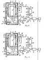
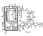
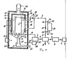
- a hot-air machine consists in its most important components of a compressor 1, a process heat exchanger 2 in a heat source 3 and a relaxation machine 4.
- the expansion machine 4 and the compressor 1 in the present case have a common drive shaft 5, with the same time an electrical Generator 6 is coupled as a working machine and a starter 7.
- the compressor 1 has an air inlet pipe 8 through which air is sucked in from the environment during operation.
- the compressed to eg 10 bar and thus preheated air leaves the compressor 1 via a pressure line 9 and flows into the process heat exchanger 2 connected thereto, from which it flows with fired heat source 3 highly heated under correspondingly high Vollumenveriererung through a supply line 10 in the expansion machine 4.
- a pressure reduction and, associated therewith, a reduction in the temperature of the process fluid flow with corresponding performance of work so that can be driven via the shaft 5 of the compressor 1 and also coupled thereto generator 6 or other work machine.
- the starter 7 can be omitted if the initial torque of the turbine is sufficient for starting the compressor 1. If, on the other hand, a hot gas engine is used as the expansion machine 4, then the starter 7 ensures the startup of the arrangement after a standstill.
- the heat source 3 can be designed to be any desired with sufficient fire power and temperature in the combustion chamber, for example, an oil, gas, coal or wood heating is suitable.
- a swirl chamber firing is preferably used as the heat source 3, in which, for example, still moist wood, straw or other suitable biomass can be successfully fired after a firing phase.
- the heat source 3 embodied as swirl chamber combustion has an outer housing 11, a combustion chamber 12 which is surrounded by a funnel-shaped downwardly sloping combustion chamber floor 13 with a central combustion opening 14, a cylindrical combustion chamber wall 15 and a combustion chamber ceiling wall 16.
- the combustion chamber wall 15 protrudes from the combustion chamber ceiling wall 16 downwards and ends at an axial distance above the combustion chamber bottom wall 13.
- Trained as a high-temperature heat exchanger process heat exchanger 2 is designed as open at both ends tube that is perpendicular to the combustion chamber 12 and ends at a distance from both the combustion chamber bottom wall 13 and the combustion chamber ceiling wall 16. Also radially, an annular space between the process heat exchanger 2 and the combustion chamber wall 15 is present.
- the process heat exchanger 2 is also the same axis with the Feuerungsö réelle 14, which opens as a pipe socket 20 in turn located in an underlying ash pot 21 freely and at a radial distance. From the ash pot 21, an operating channel 22 leads laterally out of the housing 11 to the outside, through which alternating fuel is supplied during operation and ash is discharged.
- the ash pot 21 receiving Feuerungs Kunststoffraum 23 is part of Zu Kunststoffweges the heat source 3 and pressure sealed to the outside, in the retracted operating state, the discharged from the expansion machine 4, for example, 600 degrees Celsius still relatively hot air flows through an outlet 25 into the Feuerungs Kunststoffraum 23 whereby the entire waste heat of the process fluid flow of the heat source 3 is supplied again and thus recovered.
- an intervention in the combustion process is not required.
- the resulting flame front is directed directly into the process heat exchanger 2, so that the Feuerungsgasstrom inside through the process heat exchanger upwards and after a deflection on the outside down and there partly back into the interior for re-mixing with combustion air and for further combustion in a cycle flows.
- the process heat exchanger 2 is thereby acted upon by the maximum combustion chamber temperature and heats the process fluid flow to temperatures of z. B. 860 degrees Celsius.
- the process heat exchanger 2 is accordingly also flowed around on its outside by the hot fuel gases, so that an optimal heat energy transfer to the process fluid flow and thus a high efficiency of the hot air machine is achieved in total, which is acted upon only brenstofffmasterm process fluid and thus undergoes no internal contamination and no corrosive Is exposed to fuel gases.
- an additional heat exchanger 19 is provided in an exhaust passage 17 surrounding the combustion chamber wall 15, which is connected to the pressure line 9, for example in a bypass circuit on the fluid side with two end connections. Between the corresponding connection points 26 and 27 then a gate valve 28 is connected, so that when the gate valve 28 is closed, the process fluid flow flows through this additional heat exchanger 19 and is heated by the heat energy still contained in the exhaust gas.
- the exhaust passage 17 which is connected via the gap between the combustion chamber wall 15 and the combustion chamber bottom 13 with the combustion chamber 12, yet another additional heat exchanger 18 is arranged, which preheats in case of need in any case funded by the fan 24 fresh air stream and preferably directly into the combustion chamber 12 or in the Zu Kunststoffweg 23 blows.
- Both additional heat exchangers 18, 19 can thus recover heat energy from the exhaust gas, which is supplied directly or indirectly back to the combustion process, so that a further improvement in the efficiency of the overall plant can be achieved.
- the additional heat exchangers 18 and 19 may be integrated into the combustion chamber wall 15.
- the charging can be done at times of cheap electric power tariffs by means of an electric motor associated only with the compressor. During combatifiger peak load times can then be removed from the pressure accumulator 30 at standstill compressor 1 and closed Absperschiebern 32 and 37, the stored process fluid stream. The mechanical energy generated by the expansion machine 3 can then be converted into electrical energy as a whole in the generator 6 or used for other work processes without having to expend energy on the compressor 1.
- a residual heat exchanger can be installed in the outlet 25, over the Heat energy is supplied to a Dainpfer Wegungs-, an ORC, a Kalinina, an adsorption, a space heating, or any other process with heat demand.
- a Stirling engine is directly applied to the process fluid flow of the outlet conduit 25. In this case, this possibility of use is also independent of the full or partial return of the process fluid flow to the heat source 3 given.
- Fuel with high density or coarse and large grain fuel is poorly fluidiserbar can be energetically use with a vortex chamber upstream Unterschubfeuerung 40 (Figure 2), grate furnace 50 (Fig. 3) or fluidized bed 60 ( Figure 4), wherein in the downstream Wirbelcroplaceung the fluid volume flow can be limited.
- the vortex chamber which is heated up or started with heat-up burner (oil, gas, electric, etc.) 95, can be operated with or without secondary air preheater 82 (FIG. 6). If a heat exchanger is used as secondary air preheater 82, the remaining heat exchangers 81 (or 2) and 83 are used for the power generation process by means of compressor and expansion machine. Without secondary air preheating (SL), the heat exchangers 83, 82 and 81 are for the power generation process for seduction.
- the furnace in particular the vortex chamber firing, is heated or started with oil, gas, electricity or other energy
- the system is also without power coupling d. H. can be constructed and operated without generation of electric power as pure heat generation.
Landscapes
- Engineering & Computer Science (AREA)
- Chemical & Material Sciences (AREA)
- Combustion & Propulsion (AREA)
- Mechanical Engineering (AREA)
- General Engineering & Computer Science (AREA)
- Engine Equipment That Uses Special Cycles (AREA)
Applications Claiming Priority (1)
| Application Number | Priority Date | Filing Date | Title |
|---|---|---|---|
| DE200410057637 DE102004057637A1 (de) | 2004-11-30 | 2004-11-30 | Verfahren zum Betreiben einer Heissluftmaschine und Heissluftmaschine zur Durchführung des Verfahrens |
Publications (2)
| Publication Number | Publication Date |
|---|---|
| EP1666708A2 true EP1666708A2 (fr) | 2006-06-07 |
| EP1666708A3 EP1666708A3 (fr) | 2008-08-20 |
Family
ID=36115384
Family Applications (1)
| Application Number | Title | Priority Date | Filing Date |
|---|---|---|---|
| EP05026011A Withdrawn EP1666708A3 (fr) | 2004-11-30 | 2005-11-29 | Méthode pour actionner un moteur à air chaud |
Country Status (2)
| Country | Link |
|---|---|
| EP (1) | EP1666708A3 (fr) |
| DE (2) | DE102004057637A1 (fr) |
Families Citing this family (2)
| Publication number | Priority date | Publication date | Assignee | Title |
|---|---|---|---|---|
| AT514442A1 (de) * | 2013-07-10 | 2015-01-15 | Alfred Beilschmidt | Verbrennungsofenanlage |
| CN108561203B (zh) * | 2018-06-06 | 2019-03-15 | 山东华港燃气有限公司 | 一种多功能蒸汽余热回收装置 |
Family Cites Families (4)
| Publication number | Priority date | Publication date | Assignee | Title |
|---|---|---|---|---|
| GB1500702A (en) * | 1974-03-26 | 1978-02-08 | Rolls Royce | Heat engine |
| DE3231329A1 (de) * | 1982-08-23 | 1984-02-23 | Artur Richard 6000 Frankfurt Greul | Staubbefeuerte kleingasturbine, auch fuer den fahrzeugeinsatz |
| DE3542720A1 (de) * | 1985-12-03 | 1987-06-04 | Papadopoulos Moissis | Gasturbine mit waermeaustauscher |
| US5979183A (en) * | 1998-05-22 | 1999-11-09 | Air Products And Chemicals, Inc. | High availability gas turbine drive for an air separation unit |
-
2004
- 2004-11-30 DE DE200410057637 patent/DE102004057637A1/de not_active Withdrawn
-
2005
- 2005-11-29 DE DE202005021548U patent/DE202005021548U1/de not_active Expired - Lifetime
- 2005-11-29 EP EP05026011A patent/EP1666708A3/fr not_active Withdrawn
Also Published As
| Publication number | Publication date |
|---|---|
| DE202005021548U1 (de) | 2009-03-05 |
| DE102004057637A1 (de) | 2006-06-01 |
| EP1666708A3 (fr) | 2008-08-20 |
Similar Documents
| Publication | Publication Date | Title |
|---|---|---|
| DE10228335B3 (de) | Abhitzedampferzeuger mit Hilfsdampferzeugung | |
| DE3503103A1 (de) | Verfahren und vorrichtung zur waermerueckgewinnung | |
| DE102018201172A1 (de) | Verbrennungsanlage mit Restwärmenutzung | |
| EP2612008A1 (fr) | Nettoyage des conduites de recirculation des gaz d'échappement d'une turbine à gaz | |
| CH698467B1 (de) | Vorrichtung und Verfahren zum Anfahren eines Kraftwerkes. | |
| DE19816415C2 (de) | Blockheizkraftwerk | |
| EP2492600A1 (fr) | Agencement de chauffage d'une pièce | |
| DE60106976T2 (de) | Energieerzeugungssystem | |
| DE3225140C2 (fr) | ||
| EP0613518B1 (fr) | Installation a turbines a gaz et a vapeur combinees pour la production d'energie electrique | |
| EP1666708A2 (fr) | Méthode pour actionner un moteur à air chaud | |
| DE3248623C1 (de) | Verfahren und Vorrichtung zum Vorwaermen der Verbrennungsmedien,insbesondere fuer die Beheizung von Winderhitzern fuer Hochoefen | |
| EP1643085B1 (fr) | Composant avec une installation de turbine à gaz et un générateur électrique | |
| DE202004017725U1 (de) | Anlage und Einrichtung der Kraft-Wärme-Kopplung mit Biomassegas | |
| DE4025527C1 (en) | Steam boiler with economiser - incorporates combustion chamber with recirculation circuit | |
| DE3943620C2 (de) | Feststoffvergasungsheizkessel mit Kraft- und Wärmegewinnung | |
| DE970711C (de) | Gasturbinenanlage zur Erzeugung heisser Druckluft | |
| EP1299625A1 (fr) | Procede et dispositif pour produire simultanement de la chaleur et du gaz chaud par la production combinee d'electricite et de chaleur | |
| DE102019216766A1 (de) | Verfahren zum Betrieb einer Heizvorrichtung | |
| DE19523062A1 (de) | Verbundkraftwerk mit einem Gasturbinenkraftwerk und einem Dampfkraftwerk | |
| DE102005037540B3 (de) | Kraft-Wärme-Kopplungsanlage | |
| DE10052844B4 (de) | Verfahren und Vorrichtung zur Energiegewinnung aus Gas | |
| DE175411C (fr) | ||
| DE102009034304A1 (de) | Kraftwerk | |
| DE909870C (de) | Verfahren und Vorrichtung zum Betrieb von Verpuffungsbrennkraftturbinenanlagen |
Legal Events
| Date | Code | Title | Description |
|---|---|---|---|
| PUAI | Public reference made under article 153(3) epc to a published international application that has entered the european phase |
Free format text: ORIGINAL CODE: 0009012 |
|
| AK | Designated contracting states |
Kind code of ref document: A2 Designated state(s): AT BE BG CH CY CZ DE DK EE ES FI FR GB GR HU IE IS IT LI LT LU LV MC NL PL PT RO SE SI SK TR |
|
| AX | Request for extension of the european patent |
Extension state: AL BA HR MK YU |
|
| RIC1 | Information provided on ipc code assigned before grant |
Ipc: F02C 1/02 20060101ALI20080207BHEP Ipc: F02C 3/36 20060101ALI20080207BHEP Ipc: F02C 1/04 20060101AFI20060411BHEP |
|
| PUAL | Search report despatched |
Free format text: ORIGINAL CODE: 0009013 |
|
| AK | Designated contracting states |
Kind code of ref document: A3 Designated state(s): AT BE BG CH CY CZ DE DK EE ES FI FR GB GR HU IE IS IT LI LT LU LV MC NL PL PT RO SE SI SK TR |
|
| AX | Request for extension of the european patent |
Extension state: AL BA HR MK YU |
|
| AKX | Designation fees paid | ||
| STAA | Information on the status of an ep patent application or granted ep patent |
Free format text: STATUS: THE APPLICATION IS DEEMED TO BE WITHDRAWN |
|
| 18D | Application deemed to be withdrawn |
Effective date: 20090221 |
|
| REG | Reference to a national code |
Ref country code: DE Ref legal event code: 8566 |