EP1666828A2 - Stockage de chaleur et sa méthode d'utilisation pour chauffer un fluide - Google Patents
Stockage de chaleur et sa méthode d'utilisation pour chauffer un fluide Download PDFInfo
- Publication number
- EP1666828A2 EP1666828A2 EP05025255A EP05025255A EP1666828A2 EP 1666828 A2 EP1666828 A2 EP 1666828A2 EP 05025255 A EP05025255 A EP 05025255A EP 05025255 A EP05025255 A EP 05025255A EP 1666828 A2 EP1666828 A2 EP 1666828A2
- Authority
- EP
- European Patent Office
- Prior art keywords
- thermal storage
- storage unit
- cast
- conduit
- tsu
- Prior art date
- Legal status (The legal status is an assumption and is not a legal conclusion. Google has not performed a legal analysis and makes no representation as to the accuracy of the status listed.)
- Withdrawn
Links
- 239000012530 fluid Substances 0.000 title claims abstract description 65
- 238000003860 storage Methods 0.000 title claims abstract description 53
- 238000000034 method Methods 0.000 title claims description 22
- 238000010438 heat treatment Methods 0.000 claims description 42
- 238000005266 casting Methods 0.000 claims description 30
- 239000011232 storage material Substances 0.000 claims description 16
- 238000009413 insulation Methods 0.000 claims description 12
- XEEYBQQBJWHFJM-UHFFFAOYSA-N Iron Chemical compound [Fe] XEEYBQQBJWHFJM-UHFFFAOYSA-N 0.000 claims description 10
- 238000005553 drilling Methods 0.000 claims description 7
- 239000007787 solid Substances 0.000 claims description 7
- 229910052742 iron Inorganic materials 0.000 claims description 5
- 229910000831 Steel Inorganic materials 0.000 claims description 4
- 239000010959 steel Substances 0.000 claims description 4
- 229910052782 aluminium Inorganic materials 0.000 claims description 3
- XAGFODPZIPBFFR-UHFFFAOYSA-N aluminium Chemical compound [Al] XAGFODPZIPBFFR-UHFFFAOYSA-N 0.000 claims description 3
- 229910001220 stainless steel Inorganic materials 0.000 claims description 3
- 239000010935 stainless steel Substances 0.000 claims description 3
- 230000006698 induction Effects 0.000 claims description 2
- 238000005338 heat storage Methods 0.000 abstract description 4
- 239000000463 material Substances 0.000 description 31
- 239000007789 gas Substances 0.000 description 23
- 230000008901 benefit Effects 0.000 description 9
- 230000003647 oxidation Effects 0.000 description 9
- 238000007254 oxidation reaction Methods 0.000 description 9
- 238000010276 construction Methods 0.000 description 7
- 238000004146 energy storage Methods 0.000 description 6
- 238000004519 manufacturing process Methods 0.000 description 6
- 238000002485 combustion reaction Methods 0.000 description 5
- 239000012466 permeate Substances 0.000 description 5
- 229910001141 Ductile iron Inorganic materials 0.000 description 3
- 238000009826 distribution Methods 0.000 description 3
- 239000007788 liquid Substances 0.000 description 3
- XKRFYHLGVUSROY-UHFFFAOYSA-N Argon Chemical compound [Ar] XKRFYHLGVUSROY-UHFFFAOYSA-N 0.000 description 2
- ZOKXTWBITQBERF-UHFFFAOYSA-N Molybdenum Chemical compound [Mo] ZOKXTWBITQBERF-UHFFFAOYSA-N 0.000 description 2
- 229910045601 alloy Inorganic materials 0.000 description 2
- 239000000956 alloy Substances 0.000 description 2
- 239000000919 ceramic Substances 0.000 description 2
- 230000008859 change Effects 0.000 description 2
- 238000010586 diagram Methods 0.000 description 2
- 239000000446 fuel Substances 0.000 description 2
- 238000003754 machining Methods 0.000 description 2
- 239000000203 mixture Substances 0.000 description 2
- 229910052750 molybdenum Inorganic materials 0.000 description 2
- 239000011733 molybdenum Substances 0.000 description 2
- 229920001296 polysiloxane Polymers 0.000 description 2
- 239000000047 product Substances 0.000 description 2
- 230000005855 radiation Effects 0.000 description 2
- RYGMFSIKBFXOCR-UHFFFAOYSA-N Copper Chemical compound [Cu] RYGMFSIKBFXOCR-UHFFFAOYSA-N 0.000 description 1
- 229910000589 SAE 304 stainless steel Inorganic materials 0.000 description 1
- 229910052786 argon Inorganic materials 0.000 description 1
- 230000009286 beneficial effect Effects 0.000 description 1
- 239000002131 composite material Substances 0.000 description 1
- 229910052802 copper Inorganic materials 0.000 description 1
- 239000010949 copper Substances 0.000 description 1
- 238000005260 corrosion Methods 0.000 description 1
- 230000007797 corrosion Effects 0.000 description 1
- 230000000694 effects Effects 0.000 description 1
- 230000002708 enhancing effect Effects 0.000 description 1
- 238000000605 extraction Methods 0.000 description 1
- 239000000835 fiber Substances 0.000 description 1
- 230000003116 impacting effect Effects 0.000 description 1
- 230000007246 mechanism Effects 0.000 description 1
- 238000002844 melting Methods 0.000 description 1
- 230000008018 melting Effects 0.000 description 1
- 229910052751 metal Inorganic materials 0.000 description 1
- 239000002184 metal Substances 0.000 description 1
- 150000002739 metals Chemical class 0.000 description 1
- 230000037361 pathway Effects 0.000 description 1
- 238000007493 shaping process Methods 0.000 description 1
Images



Classifications
-
- F—MECHANICAL ENGINEERING; LIGHTING; HEATING; WEAPONS; BLASTING
- F28—HEAT EXCHANGE IN GENERAL
- F28D—HEAT-EXCHANGE APPARATUS, NOT PROVIDED FOR IN ANOTHER SUBCLASS, IN WHICH THE HEAT-EXCHANGE MEDIA DO NOT COME INTO DIRECT CONTACT
- F28D20/00—Heat storage plants or apparatus in general; Regenerative heat-exchange apparatus not covered by groups F28D17/00 or F28D19/00
- F28D20/0056—Heat storage plants or apparatus in general; Regenerative heat-exchange apparatus not covered by groups F28D17/00 or F28D19/00 using solid heat storage material
-
- Y—GENERAL TAGGING OF NEW TECHNOLOGICAL DEVELOPMENTS; GENERAL TAGGING OF CROSS-SECTIONAL TECHNOLOGIES SPANNING OVER SEVERAL SECTIONS OF THE IPC; TECHNICAL SUBJECTS COVERED BY FORMER USPC CROSS-REFERENCE ART COLLECTIONS [XRACs] AND DIGESTS
- Y02—TECHNOLOGIES OR APPLICATIONS FOR MITIGATION OR ADAPTATION AGAINST CLIMATE CHANGE
- Y02E—REDUCTION OF GREENHOUSE GAS [GHG] EMISSIONS, RELATED TO ENERGY GENERATION, TRANSMISSION OR DISTRIBUTION
- Y02E10/00—Energy generation through renewable energy sources
- Y02E10/20—Hydro energy
-
- Y—GENERAL TAGGING OF NEW TECHNOLOGICAL DEVELOPMENTS; GENERAL TAGGING OF CROSS-SECTIONAL TECHNOLOGIES SPANNING OVER SEVERAL SECTIONS OF THE IPC; TECHNICAL SUBJECTS COVERED BY FORMER USPC CROSS-REFERENCE ART COLLECTIONS [XRACs] AND DIGESTS
- Y02—TECHNOLOGIES OR APPLICATIONS FOR MITIGATION OR ADAPTATION AGAINST CLIMATE CHANGE
- Y02E—REDUCTION OF GREENHOUSE GAS [GHG] EMISSIONS, RELATED TO ENERGY GENERATION, TRANSMISSION OR DISTRIBUTION
- Y02E60/00—Enabling technologies; Technologies with a potential or indirect contribution to GHG emissions mitigation
- Y02E60/14—Thermal energy storage
-
- Y—GENERAL TAGGING OF NEW TECHNOLOGICAL DEVELOPMENTS; GENERAL TAGGING OF CROSS-SECTIONAL TECHNOLOGIES SPANNING OVER SEVERAL SECTIONS OF THE IPC; TECHNICAL SUBJECTS COVERED BY FORMER USPC CROSS-REFERENCE ART COLLECTIONS [XRACs] AND DIGESTS
- Y10—TECHNICAL SUBJECTS COVERED BY FORMER USPC
- Y10S—TECHNICAL SUBJECTS COVERED BY FORMER USPC CROSS-REFERENCE ART COLLECTIONS [XRACs] AND DIGESTS
- Y10S165/00—Heat exchange
- Y10S165/539—Heat exchange having a heat storage mass
-
- Y—GENERAL TAGGING OF NEW TECHNOLOGICAL DEVELOPMENTS; GENERAL TAGGING OF CROSS-SECTIONAL TECHNOLOGIES SPANNING OVER SEVERAL SECTIONS OF THE IPC; TECHNICAL SUBJECTS COVERED BY FORMER USPC CROSS-REFERENCE ART COLLECTIONS [XRACs] AND DIGESTS
- Y10—TECHNICAL SUBJECTS COVERED BY FORMER USPC
- Y10S—TECHNICAL SUBJECTS COVERED BY FORMER USPC CROSS-REFERENCE ART COLLECTIONS [XRACs] AND DIGESTS
- Y10S165/00—Heat exchange
- Y10S165/902—Heat storage
Definitions
- This invention relates to thermal storage units (TSUs). More particularly, this invention relates to TSUs that provide sensible heat thermal energy storage and delivery in a way that increases efficiency and reduces costs compared to known TSUs.
- TSUs are well known and are often used in power delivery systems, such as compressed air storage (CAS) systems and thermal and compressed air storage (TACAS) systems.
- CAS compressed air storage
- TACAS thermal and compressed air storage
- Such systems often used to provide an available source of electrical power, often use compressed air to drive a turbine which powers an electrical generator.
- TSU fuel-combustion system
- TSUs may offer advantages over fuel-combustion systems
- existing TSUs have several shortcomings, as discussed below.
- TSUs are typically designed to take many of the following design considerations into account:
- TSU 10 of FIG. 1 includes heated parallel plates 12 contained within housing 14 to create channels through which compressed gas may flow.
- the heat transfer area and the gap between plates 12 may be adjusted for optimum heat transfer conditions.
- Such a TSU is not optimally suited for high pressure operation as these plates do not provide optimum pressure containment for the compressed gas, and instead result in leakage flow between plates 12 and housing 14.
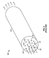
- TSU uses tube flow through elongated cavities embedded in a solid medium. As shown in FIG. 2, compressed gas travels through through-holes 22, which are bored out of bar 24. Although tube flow, as provided by TSU 20 of FIG. 2, may provide more desirable pressure containment compared to channel flow TSU 10 of FIG. 1, it involves high fabrication costs. This is because it is usually costly to drill a plurality of small-diameter holes that extend throughout the entire length of a solid medium.
- the TSUs shown in FIGS. 1 and 2 fail to provide means for effectively containing and delivering heated and compressed air in a manner that is cost beneficial.
- the foregoing TSUs are limited in design flexibility at least because they either require machining or assembly of several parts to provide fluid conducting passageways.
- a TSU that is constructed using a casting process.
- a TSU according to the present invention may be constructed by first providing a conduit (or fluid conducting structure) and then subjecting that conduit to a casting process.
- the conduit may provide a pathway through which fluid flows through the TSU and the casting process may yield a cast that envelops the conduit with thermal storage material.
- the cast may have desirable thermal mass or thermal storage properties and may be fabricated from inexpensive material, such as ductile iron.
- the cast may permeate and occupy substantially all free space existing immediately adjacent to and near the conduit, resulting in a cohesive and integrated TSU in which the conduit and the cast may be fused together.
- a solid thermal conducting mass having a fluid conducting passageway, as defined by the conduit, is provided.
- TSU may include a conduit that is a parallelepiped structure (e.g., a structure in which the fluid path passes back and forth along a particular axis a predetermined number of times), which is contained within a cast. It may not be possible to construct such a TSU using conventional machining techniques, and even if it were possible, the cost would be prohibitively expensive.
- a parallelepiped structure e.g., a structure in which the fluid path passes back and forth along a particular axis a predetermined number of times
- the cast may permeate and occupy the free space existing between the parallelepiped structure, thereby maximizing the heat storage capacity and heat transfer capacity of the TSU.
- the cast may provide structural support for the TSU, thereby enabling it to contain pressurized fluids.
- the TSU may be heated to a predetermined temperature or a predetermined range of temperatures. This may be accomplished using a heating system that uses internal or external heaters to heat the cast.
- internal heaters such as cartridge heaters may be housed in holes bored into the cast of the TSU. When active, the internal heaters radiate heat to the cast, thereby raising the temperature of the TSU to a desired temperature.
- the TSU according to the invention may be used in a TACAS system.
- compressed gas may be sensibly heated by the TSU before it is routed to a turbine inlet of a turbine-generator.
- the heated compressed air drives a turbine, which powers an electrical generator to provide electrical power.
- An advantage of using the TSU according to the invention is that it may heat the compressed gas without requiring the use fuels, which when combusted cause pollution.
- FIG. 1 is a top perspective view of a known thermal storage unit
- FIG. 2 is a top perspective view of another known thermal storage unit
- FIGS. 3A-C show perspective and cross-sectional views of an illustrative thermal storage unit in accordance with the principles of the present invention
- FIG. 4 shows a TSU having internal heating elements contained within cavities of the TSU in accordance with the principles of the present invention.
- FIG. 5 is a perspective view of a conduit network thermal storage unit that may be subjected to a casting process in accordance with the principles of the present invention
- FIG. 6 is a perspective view of the TSU of FIG. 5 having a cast in accordance with the principles of the present invention
- FIGS. 7A-B show heat transfer diagrams of a portion of the TSU of FIG. 3 during different time frames of a heat transfer event in accordance with the principles of the present invention
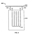
- FIG. 8 is a partial sectional view of the thermal storage unit of FIG. 3 in a storage configuration in accordance with the principles of the present invention.
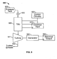
- FIG. 9 is a simplified schematic diagram of a thermal and compressed air storage system employing a thermal storage unit in accordance with the principles of the present invention.
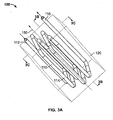
- FIGS. 3A-C shows several views of a thermal storage unit (TSU) 100 that is in accordance with the principles of the present invention.
- FIG. 3A shows a three-dimensional view of thermal storage unit (TSU) 100 that is in accordance with the principles of the present invention.
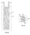
- FIG. 3B shows a cross-sectional view of TSU 100 taken along the lines 3B-3B of FIG. 3A in accordance with the principles of the present invention.
- FIG. 3C shows a cross-sectional view of TSU 100 taken along the lines 3C-3C of FIG. 3A. It will be understood that any reference to FIG. 3 may include a reference to any one of FIGS. 3A-C.
- TSU 100 may include conduit 110 and cast 120 and have longitudinal axis 150.
- conduit 110 e.g., conduit body 114
- inlet 112 and outlet 116 may remain unenclosed by the box.
- This box represents a cast 120 that envelops conduit 110 according to the invention.
- the manner or nature in which cast 120 envelops conduit 110 may depend on the casting method or technique used to create cast 120. For example, the casting process may result in a bond between the outer walls of conduit body 114 and the casting material (e.g., iron, steel, or alloys thereof) without resulting in excessive loss of conduit wall thickness due to melting.
- the casting material e.g., iron, steel, or alloys thereof
- TSU 100 is a solid thermal conducting mass having a fluid conducting passageway, as defined by conduit 110, contained therein.
- TSU 100 includes inlet 112, for permitting a fluid to flow into conduit 110, and outlet 116, for permitting the fluid to flow out of conduit 110.
- Fluid may be matter in a liquid or gas state, matter transitioning between a liquid and gas state, or a combination thereof.
- the fluid may be air, argon, or any other suitable gas.
- Other fluids may be used that change phase (e.g., change from a solid to a liquid) as the temperature of the fluid changes.
- TSU 100 may be used to heat or cool the fluid flowing through conduit 110, depending on the application in which TSU 100 is being used. For purposes of clarity and simplicity, it will be assumed that TSU 100 is used to heat fluid. In TACAS applications, for example, TSU 100 may heat the fluid to a predetermined range of temperatures for driving a turbine-generator. (A more detailed discussion of the operation of a turbine-generator in connection with TACAS system is discussed below in the text accompanying FIG. 9). It is noted that turbine-generators generally operate more efficiently when the fluid being supplied to the turbine inlet ranges between a predetermined temperature and pressure. Therefore, it is understood that a thermal storage unit, such as TSU 100, may be needed to heat the fluid to a predetermined temperature without substantially affecting the pressure of the fluid passing through the TSU.
- TSU 100 addresses these temperature and pressure requirements, as well as other criteria such as physical dimensions of the TSU, the mass flow rate of fluid through the TSU, and reliable and safe operation in high pressure applications, by constructing the TSU with conduit 110 and cast 120 according to the invention.
- This conduit 110 and cast 120 construction provides enhanced design flexibility at relatively low manufacturing costs not previously attained by the prior art. Low manufacturing costs may be achieved because conventional products and materials may be used to construct conduit 110 and cast 120.
- the conduit and cast construction eliminates the need to perform time consuming and expensive drilling (e.g., high precision and/or tolerance drilling) to provide one or more fluid conducting passageways.
- conduit 110 may be designed independent of cast 120.
- conduit 110 may be a parallelepiped structure such as that shown in FIG. 3 or it may be a helical or coil shaped structure, a tubing coil, a piping coil, pipe network, or other suitable fluid conducting structure.
- a parallelepiped structure may be a conduit that routes fluid back and forth multiple times on axes substantially parallel to axis 150.
- Conduit 110 may be a single piece or multiple piece construction.
- conduit 110 may be seamless in construction.
- it may be a long pipe (e.g., a forty foot pipe having a predetermined inner diameter) that is bent into a predetermined shape (e.g., a parallelepiped shape).
- a multiple piece construction may be an assembly of components connected to create a continuous flow path.
- such construction may includes a series of pipes or other flow conducting members connected together in a predetermined configuration.
- Conduit 110 may be constructed from materials that have suitable thermal conductivity and that are capable of containing pressure and withstanding temperature variations.
- one suitable material may be a stainless steel such as 304 steel.
- conventional steel, iron, aluminum, or copper piping may be used.
- conduit 110 may be constructed from materials that have a high resistance to oxidation.
- inlet 112 and outlet 116 may be a matter a design choice.
- both inlet 112 and outlet 116 may be positioned on the same end of the TSU or on opposite ends.
- the inlet and outlet need not protrude from cast 120 parallel with axis 150. If desired, inlet and outlet may protrude from cast 120 perpendicular to axis 150.
- Design flexibility is further achieved because cast 120, when in its amorphous or molten state, envelops and bonds to conduit 110, regardless of the shape of conduit 110.
- the "external" shape of cast 120 may be set to have pre-determined dimensions (e.g., a rectangular or circular shape of desired dimensions) while the cast is in its amorphous or molten state.
- This flexibility in shaping the casting material provides for a TSU that may be custom fit into an integrated package such as a TACAS backup power supply system.
- cast 120 may be shaped to minimize the external surface area, thereby maximizing the heating capacity and potential for retaining heat within the thermal storage material. Insulation may be used to further enhance the heating capacity and potential to retain heat.
- cast 120 may be made to have a rectangular shape (e.g., 10" x 10" x 30" rectangular box), which may be easily manufactured and packaged.
- the rectangular shape may be an ideal cast for a parallelepiped conduit structure such as that shown in FIG. 3.
- Cast 120 may be obtained through one or multiple casting stages.
- the casting material may be applied to conduit body 114 in one step to create the TSU according to the invention.
- the casting material may be applied to conduit body 114 in several steps using, for example, different materials in each step. For example, certain materials may be applied to ensure a bond between adjacent layers of the cast material and to minimize porosity or sponginess in the cast.
- Cast 120 may include one or more types of materials that exhibit desirable thermal mass and or thermal storage properties. Such materials may include, for example, iron, steel, stainless steel, aluminum, other metals, or alloys and composites thereof. If desired, such materials may be ductile to permit ease of drilling, for example, of holes in which heating elements may be inserted. Other more advanced casting materials may be used to further enhance the thermal energy storage capacity.
- One such material is high silicone molybdenum ductile iron, which is alloyed with silicone and molybdenum to allow the material to be used at a higher temperature, enhancing energy storage performance.
- conduit 110 may be positioned concentrically within cast 120, irrespective of the cast's shape, to provide a relatively equal distribution of thermal storage material on each side of conduit 110. Such a distribution may promote more uniform and complete extraction of energy from cast 120.
- TSU 100 may be designed to have specific mass flow and heat transfer characteristics. Optimizing such characteristics may be useful, for example, in a system (e.g., a TACAS system) that utilizes heated compressed gas to drive a turbine-generator.
- the mass flow rate of fluid flowing through TSU 100 may be a function of one or more of the following criteria: the pressure of the fluid applied to inlet 112 of TSU 100, the shape of conduit 110, the cross-sectional area of conduit 110, and the length of conduit 110. It is appreciated that many of these criteria (e.g., shape, cross-sectional area, and length of conduit 110) can be accounted for based on the design of conduit 110. As such, TSU 100 may exhibit desired mass flow properties such as a predetermined pressure drop across the TSU.
- the heat transfer rate may be a function of one or more of the following criteria: the temperature of conduit 110 and cast 120, the convection coefficient, which may depend on the mass flow rate (described above), the surface area of conduit 110 exposed to cast 120, and the surface area of fluid exposed to the inner walls of conduit 110. It will be appreciated that many or all of these criteria can be accounted for when designing and manufacturing TSU 100 in accordance with the principles of the present invention. That is, the design flexibility of both conduit 110 and cast 120 enables a TSU to be constructed that rapidly heats (or cools) a fluid to a predetermined temperature.
- TSU 100 may be heated to and maintained at a predetermined temperature using a heating system (examples of which are discussed below) so that heat stored in the thermal storage material (e.g., cast 120) of TSU 100 can be transferred to a fluid flowing through TSU 100.
- TSU 100 may be heated and maintained at a predetermined temperature while utility power is available and TSU 100 may transfer heat to a fluid when utility power is not available.
- An example of such an embodiment is described in more detail below in connection with FIG. 9. It is noted that because thermal storage material permeates TSU 100, as a result of the casting process, heat may be conducted relatively easily throughout TSU 100, regardless of which heating technique is used.
- TSU 100 may be heated using one or more of many different heating techniques. Some of these techniques preferably may use exhaustless or non-polluting methods to heat TSU 100. Though exhaustless or non-polluting methods are preferred, it will be appreciated that pollution causing heating techniques (e.g., techniques that use fuel) may be implemented to heat TSU 100. Regardless of the technique used, cast 120 may be heated by radiation means of an external or internal heater.
- an external heater may include a ceramic fiber heater that is attached to the outer surface of TSU 100 heats cast 120 through radiation when actuated.
- An internal heater may, for example, include heating elements (e.g., heating rods or cartridge heaters) that are placed into one or more cavities extending through a portion or the entire length of TSU 100.
- heating elements When such heating elements are actuated, they transfer heat to the thermal storage material (e.g., cast 120 and conduit 110) of TSU 100.
- thermal storage material e.g., cast 120 and conduit 110
- '636 application e.g., cartridge heating system
- FIG. 4 shows a cross-sectional view of a TSU employing an internal heating system in accordance with the principles of the present invention.
- the heating system includes a plurality of heating elements 122 that are removably inserted into holes 124 of TSU 100.
- the heating elements may be electrical resistance heating elements such as cartridge heaters such as those described in the '636 application.
- Holes 124 may be provided by drilling into cast 120 after the cast sets or cools. The number of and placement of such holes is a matter a design choice, but the holes are preferably drilled such that conduit 110 is not punctured, thereby ensuring that pressure containment is maintained when fluid flows through TSU 100. Moreover, such holes need not be drilled with extremely tight tolerances or dimensions and therefore may not require expensive and time-consuming drilling techniques.
- holes 124 may be obtained by subjecting hollow tubes (as shown in FIGS. 5 and 6) to the casting process.
- the thermal storage material of TSU 100 may be heated by any other suitable type of heating system.
- a resistive heater may provide a heat source that is in physical contact with the thermal storage material of TSU 100 and may heat this material to a predetermined temperature.
- electrically conductive thermal storage materials such as iron, may be heated inductively using induction heating circuitry that causes current to circulate through and heat the thermal storage material of TSU 100.
- the invention is not limited to the specific heating techniques discussed above.
- Insulation may be used to improve the heat capacity of TSU 100. That is, the insulation may permit TSU 100 to be heated to temperatures not possible in the absence of insulation because of heat losses. In addition, insulation may permit TSU 100 to maintain a predetermined temperature, while requiring less power to maintain such a temperature.
- the insulation may blanket all or a portion of TSU 100 and may be shaped to conform to the outer surface of TSU 100.
- the insulation may include any material that provides heat retention.
- the insulation may include ceramic insulation or microporous board insulation.
- TSU 100 described the use of one conduit that is subjected to a casting process to produce a TSU according to the present invention.
- a TSU may be constructed to have multiple conduits contained within a cast according to the present invention.
- two or more conduits of a desired size and shape are subjected to a casting process to provide the TSU.
- a conduit network such as a single annular channel or multiple annular channel TSU
- An annular channel may be contained between an inner member and an outer member, both of which may include thermal mass or thermal storage material having desirable energy or heat storage properties and may be fabricated using standard mill products.
- the annular channel may be coupled to a port or pipe on each end of the channel for either providing fluid thereto or projecting fluid therefrom.
- the TSU may include multiple substantially parallel annular flow channels, each being contained between the outer member and a different inner member. If desired, the multiple substantially parallel annular flow channels may be coupled to each other via transverse channels such that various fluid routing arrangements and piping connections are made possible within the TSU.
- FIG. 5 shows a perspective view of conduit network (e.g., multiple annual channel) 500 that may be subjected to a casting process in accordance with the principles of the present invention.
- network 500 includes four annular channels 510a-d.
- each channel 510a-d may include an annular channel.
- Channels 510a-d may be interconnected via transverse members 518, which provides flexibility in routing fluid through TSU 500.
- transverse members 518 Depending on the configuration of transverse members 518, a four-pass/one-path or a two-pass/two-path arrangement may be provided.
- the two-pass/two-path arrangement is shown in FIG. 5.
- fluid may be supplied to inlet 512 and may then flow along two different paths: 1) through channel 510a then channel 510b, and 2) through channel 510c then channel 510d, before exiting through outlet 516.
- tubes 514 which are disposed between channels 510a-d. Tubes 514 may be used to hold heating elements such as cartridge heaters, as discussed above. Thus, when network 500 is contained within a cast, the holes provided by tubes 514 may eliminate the need to drill holes into the cast to provide receptacles for heating elements. Those of skill in the art will appreciate, however, that holes may be drilled into the cast, in addition to the holes provided by tubes 514.
- FIG. 6 shows the pipe network of FIG. 5 contained within a cast in accordance with the principles of the present invention.
- Cast 520 may be cast such that it encapsulates and permeates all space existing between channels 510a-d, tubes 514, and transverse members 518, but does not cover the openings of inlet 512, tubes 514, or outlet 516. It is noted that with cast 520 disposed about network 500, the thermal storage capacity and the structural support of channels 510a-d is increased. It is further noted that heat retention and heating capacity can be further increased using insulation, as discussed above.
- TSU may have a reduced susceptibility to oxidation, also known as "fouling."
- the cast material may be ductile iron, which may be susceptible to oxidation if left untreated, fluids passing through the TSU may not come into contact with the cast because the conduit provides sufficient pressure containment.
- the cast and/or conduit may be coated with a corrosion resistant layer.
- TSU 20 includes long, small diameter through holes 22 which conduct flow of fluid.
- a small amount of oxidation in through holes 22 may reduce the surface area of the through hole by a significant percentage and lower the heat transfer rate of TSU 20.
- the TSU according to the present invention can be constructed to have fluid conduits that are substantially larger (e.g., have greater cross-sectional areas) than that of the prior art, a small amount of oxidation may have minimal or negligible affect on the surface area and the heat transfer rate.
- Another advantage of the present invention over the systems known in the art is that manufacturers may select two different materials for the two different components of the TSU: a casting material that has good high temperature properties and a low cost to cast, and a conduit material that has good high temperature and high pressure properties and is oxidation resistant. Manufacturers and designers may no longer be required to select a single material that is both oxidation resistant and has both high temperature and high pressure properties at potentially high cost.
- Yet another advantage of the invention is two "levels" of pressure containment are provided. The first being provided by the conduit and the second being provided by the cast, which surrounds the conduit. Thus, if pressure containment of the conduit fails, the cast may function as a backup source of pressure containment.
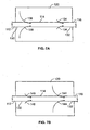
- FIGS. 7A and 7B show partial sectional views of TSU 100 of FIG. 3 to illustrate heat transfer to fluid flowing through the TSU at different times during a heat transfer event.
- the average temperature of cast 120 may be less than the desired turbine inlet temperature, but the cast may still retain enough heat to raise the temperature of the fluid to the desired inlet temperature.
- heat is first removed from proximal portion 130 of cast 120, adjacent inlet 112, as shown in FIG. 7A.
- the heat flow in the proximal portion shown by arrows 136, may be larger than the heat flow in distal portion 132, adjacent outlet 116, shown by arrows 134.
- proximal portion 130 of cast 120 After a predetermined period of time, a majority of the heat may be removed from proximal portion 130 of cast 120, as shown in FIG. 7B.
- FIG. 8 shows a storage configuration of a TSU in accordance with the principles of the invention.
- This storage configuration takes into account thermal expansion of the cast and/or conduit that may occur during the operation of TSU 800.
- One way to avoid potential problems that may arise out of expansion is to design the TSU such that piping connections to other portions of the system are not made on opposite ends of the TSU.
- FIG. 8 shows such a configuration in which TSU 800 is mounted to support 860 using securing portion 862 such that TSU hangs from support 860. More particularly, the cast of TSU 860 may be mounted to support 860 to permit unrestricted expansion of the conduit, including the inlet and outlet, and the cast. This unrestricted expansion may avoid potential ruptures of the conduit, including the inlet and outlet, as TSU 800 expands, while not impacting the way in which TSU 800 is used.
- TACAS thermal and compressed air storage
- TACAS system 900 is not intended to be a thorough explanation of the components of a TACAS, but rather an illustration of how a TSU according to the present invention can enhance the performance of a TACAS system.
- a TACAS system see commonly-assigned, co-pending U.S. patent application No. 10/361,728, filed February 5, 2003, which is hereby incorporated by reference herein in its entirety.
- TACAS system 900 includes storage or pressure tank 923, valve 932, TSU 909, electrical input 910, turbine 941, generator 942 and electrical output 950.
- compressed gas from pressure tank 923 may be routed through valve 932 to TSU 909.
- TSU 909 may heat the compressed gas before it is provided to turbine 941.
- turbine-generators operate more efficiently when the temperature of the fluid supplied to the turbine inlet ranges between a predetermined range of temperatures. For example, the average desired turbine inlet temperature may be about 450° F.
- the hot gas emerging from TSU 909 may flow against the turbine rotor (not shown) of turbine 941, which may be any suitable type of turbine system (e.g., a radial-flow turbine).
- the heated compressed gas drives the turbine rotor, causing turbine 941 to drive electrical generator 942, which produces electric power and provides it to electrical output 950.
- turbine exhaust 943 e.g., the exhaust gases emerging from turbine 941).
- Turbine exhaust 943 may be vented through an exhaust pipe (not shown), or simply released to recombine with atmospheric air.
- TSU 909 is heated to a predetermined temperature or range of temperatures.
- TSU 909 may be heated to about 1,300° F.
- TSU 909 may use an exhaustless (e.g., non-polluting) heating system, which is powered by electrical input 910.
- TSU 909 may include an external or internal heating system, as discussed above.
- System 900 therefore provides the benefits of heating compressed air from pressure tank 923 before it is supplied to turbine 941, without producing the harmful emissions associated with combustion heating systems.
- the heating system may heat and maintain TSU 909 at a predetermined temperature or at a predetermined range of temperatures while system 900 is in a standby mode of operation (e.g., utility power is available).
- TACAS system 900 may also include control circuitry 920 which may be coupled to both TSU 909 and electrical input 910.
- Control circuitry 920 may include means for measuring the temperature of TSU 909.
- Control circuitry 920 may also include electric circuitry for controlling the temperature of TSU 909.
- Control circuitry 920 may control the temperature of TSU 909 by, for example, controlling the electric power provided to the heating system. This may be achieved by providing instructions to electrical input 910, such as instructions to activate, deactivate, increase or decrease the output of electrical input 910.
- Control circuitry 920, along with electrical input 910 may therefore be used to monitor and control the temperature of TSU 909.
- the temperature of the compressed gas exiting TSU 909 may be substantially higher than the desired turbine inlet temperature. Thus, it may be necessary to lower the temperature of the compressed gas before it is supplied to the turbine inlet.
- One way to control the temperature of the compressed gas being supplied to the turbine inlet is to use a bypass path fluid routing system which selectively controls the mass flow of heated and non-heated air supplied to the inlet of the turbine.
- the bypass path fluid routing system may include a path (not shown) that routes unheated gas through a path that bypasses TSU 909 and feeds into turbine 941.
- the ratio of heated to non-heated air provided to turbine 941 may be modified, thereby providing a method for controlling the temperature of the air being supplied to the turbine.
- the ratio of unheated compressed gas routed through the bypass path may decrease accordingly to maintain a desired turbine inlet temperature.
- the present invention may be used in any application associated with generating power, such as in thermal and solar electric plants.
- the present invention may be used in any other application where thermal storage, fluid heating or heated fluid delivery may be desirable.
Landscapes
- Engineering & Computer Science (AREA)
- Physics & Mathematics (AREA)
- Thermal Sciences (AREA)
- Mechanical Engineering (AREA)
- General Engineering & Computer Science (AREA)
- Pipe Accessories (AREA)
- Other Liquid Machine Or Engine Such As Wave Power Use (AREA)
Applications Claiming Priority (1)
| Application Number | Priority Date | Filing Date | Title |
|---|---|---|---|
| US10/993,877 US7693402B2 (en) | 2004-11-19 | 2004-11-19 | Thermal storage unit and methods for using the same to heat a fluid |
Publications (1)
| Publication Number | Publication Date |
|---|---|
| EP1666828A2 true EP1666828A2 (fr) | 2006-06-07 |
Family
ID=35825331
Family Applications (1)
| Application Number | Title | Priority Date | Filing Date |
|---|---|---|---|
| EP05025255A Withdrawn EP1666828A2 (fr) | 2004-11-19 | 2005-11-18 | Stockage de chaleur et sa méthode d'utilisation pour chauffer un fluide |
Country Status (3)
| Country | Link |
|---|---|
| US (1) | US7693402B2 (fr) |
| EP (1) | EP1666828A2 (fr) |
| JP (1) | JP2006145200A (fr) |
Cited By (3)
| Publication number | Priority date | Publication date | Assignee | Title |
|---|---|---|---|---|
| WO2020254001A1 (fr) | 2019-06-17 | 2020-12-24 | E2S Power AG | Dispositif et procédé de stockage d'énergie |
| CN114041036A (zh) * | 2019-06-17 | 2022-02-11 | E2S电力公司 | 能量存储装置及存储能量的方法 |
| EP4257908A1 (fr) | 2022-04-05 | 2023-10-11 | E2S Power Ag | Dispositif de stockage d'énergie et procédé de stockage d'énergie au moyen d'unités de stockage d'énergie thermique connectées en série |
Families Citing this family (51)
| Publication number | Priority date | Publication date | Assignee | Title |
|---|---|---|---|---|
| US20080289793A1 (en) * | 2007-05-22 | 2008-11-27 | Gerald Geiken | Thermal energy storage systems and methods |
| AU2008262309A1 (en) | 2007-06-06 | 2008-12-18 | Areva Solar, Inc. | Combined cycle power plant |
| US8378280B2 (en) * | 2007-06-06 | 2013-02-19 | Areva Solar, Inc. | Integrated solar energy receiver-storage unit |
| US20090126364A1 (en) * | 2007-06-06 | 2009-05-21 | Ausra, Inc. | Convective/radiative cooling of condenser coolant |
| US20090056703A1 (en) | 2007-08-27 | 2009-03-05 | Ausra, Inc. | Linear fresnel solar arrays and components therefor |
| US9022020B2 (en) | 2007-08-27 | 2015-05-05 | Areva Solar, Inc. | Linear Fresnel solar arrays and drives therefor |
| US8474255B2 (en) | 2008-04-09 | 2013-07-02 | Sustainx, Inc. | Forming liquid sprays in compressed-gas energy storage systems for effective heat exchange |
| US8677744B2 (en) | 2008-04-09 | 2014-03-25 | SustaioX, Inc. | Fluid circulation in energy storage and recovery systems |
| US7958731B2 (en) | 2009-01-20 | 2011-06-14 | Sustainx, Inc. | Systems and methods for combined thermal and compressed gas energy conversion systems |
| US8240140B2 (en) | 2008-04-09 | 2012-08-14 | Sustainx, Inc. | High-efficiency energy-conversion based on fluid expansion and compression |
| US8225606B2 (en) | 2008-04-09 | 2012-07-24 | Sustainx, Inc. | Systems and methods for energy storage and recovery using rapid isothermal gas expansion and compression |
| US8359856B2 (en) | 2008-04-09 | 2013-01-29 | Sustainx Inc. | Systems and methods for efficient pumping of high-pressure fluids for energy storage and recovery |
| US8448433B2 (en) | 2008-04-09 | 2013-05-28 | Sustainx, Inc. | Systems and methods for energy storage and recovery using gas expansion and compression |
| EP2280841A2 (fr) | 2008-04-09 | 2011-02-09 | Sustainx, Inc. | Systèmes et procédés de stockage et de récupération d'énergie à l aide de gaz comprimé |
| US20100307156A1 (en) | 2009-06-04 | 2010-12-09 | Bollinger Benjamin R | Systems and Methods for Improving Drivetrain Efficiency for Compressed Gas Energy Storage and Recovery Systems |
| US8479505B2 (en) | 2008-04-09 | 2013-07-09 | Sustainx, Inc. | Systems and methods for reducing dead volume in compressed-gas energy storage systems |
| US8037678B2 (en) | 2009-09-11 | 2011-10-18 | Sustainx, Inc. | Energy storage and generation systems and methods using coupled cylinder assemblies |
| US8250863B2 (en) | 2008-04-09 | 2012-08-28 | Sustainx, Inc. | Heat exchange with compressed gas in energy-storage systems |
| DE102008047557A1 (de) * | 2008-05-30 | 2009-12-03 | Deutsches Zentrum für Luft- und Raumfahrt e.V. (DLR) | Vorrichtung und Anlage zum Speichern von thermischer Energie |
| WO2009152141A2 (fr) | 2008-06-09 | 2009-12-17 | Sustainx, Inc. | Système et procédé pour la détente et la compression isotherme rapide de gaz pour le stockage d'énergie |
| US7963110B2 (en) | 2009-03-12 | 2011-06-21 | Sustainx, Inc. | Systems and methods for improving drivetrain efficiency for compressed gas energy storage |
| US8104274B2 (en) | 2009-06-04 | 2012-01-31 | Sustainx, Inc. | Increased power in compressed-gas energy storage and recovery |
| WO2011056855A1 (fr) | 2009-11-03 | 2011-05-12 | Sustainx, Inc. | Systèmes et procédés de stockage d'énergie produite par un gaz comprimé au moyen d'ensembles vérins couplés |
| US8171728B2 (en) | 2010-04-08 | 2012-05-08 | Sustainx, Inc. | High-efficiency liquid heat exchange in compressed-gas energy storage systems |
| US8191362B2 (en) | 2010-04-08 | 2012-06-05 | Sustainx, Inc. | Systems and methods for reducing dead volume in compressed-gas energy storage systems |
| US8234863B2 (en) | 2010-05-14 | 2012-08-07 | Sustainx, Inc. | Forming liquid sprays in compressed-gas energy storage systems for effective heat exchange |
| US8978380B2 (en) | 2010-08-10 | 2015-03-17 | Dresser-Rand Company | Adiabatic compressed air energy storage process |
| US8495872B2 (en) | 2010-08-20 | 2013-07-30 | Sustainx, Inc. | Energy storage and recovery utilizing low-pressure thermal conditioning for heat exchange with high-pressure gas |
| JP2012077939A (ja) * | 2010-09-30 | 2012-04-19 | Panasonic Corp | 蓄熱装置及び該蓄熱装置を備えた空気調和機 |
| US8578708B2 (en) | 2010-11-30 | 2013-11-12 | Sustainx, Inc. | Fluid-flow control in energy storage and recovery systems |
| JP2014522460A (ja) | 2011-05-17 | 2014-09-04 | サステインエックス, インコーポレイテッド | 圧縮空気エネルギー貯蔵システムにおける効率的二相熱移送のためのシステムおよび方法 |
| US20130091836A1 (en) | 2011-10-14 | 2013-04-18 | Sustainx, Inc. | Dead-volume management in compressed-gas energy storage and recovery systems |
| JP2013120030A (ja) * | 2011-12-08 | 2013-06-17 | Panasonic Corp | 空気調和機 |
| SE536723C2 (sv) | 2012-11-01 | 2014-06-24 | Skanska Sverige Ab | Termiskt energilager innefattande ett expansionsutrymme |
| SE537267C2 (sv) | 2012-11-01 | 2015-03-17 | Skanska Sverige Ab | Förfarande för drift av en anordning för lagring av termiskenergi |
| SE536722C2 (sv) * | 2012-11-01 | 2014-06-17 | Skanska Sverige Ab | Energilager |
| US9938895B2 (en) | 2012-11-20 | 2018-04-10 | Dresser-Rand Company | Dual reheat topping cycle for improved energy efficiency for compressed air energy storage plants with high air storage pressure |
| US11555658B2 (en) * | 2014-11-19 | 2023-01-17 | University of Alaska Anchorage | Methods and systems to convert passive cooling to active cooling |
| US20190137191A1 (en) * | 2017-11-06 | 2019-05-09 | Johnathan Lawrence | Thermal Capacitor |
| US12291982B2 (en) | 2020-11-30 | 2025-05-06 | Rondo Energy, Inc. | Thermal energy storage systems for use in material processing |
| MA71196B1 (fr) | 2020-11-30 | 2025-04-30 | Rondo Energy, Inc. | Système et applications de stockage d'énergie |
| US12359591B1 (en) * | 2020-11-30 | 2025-07-15 | Rondo Energy, Inc. | Thermal energy storage systems for repowering existing power plants for improving efficiency and safety |
| US11913362B2 (en) | 2020-11-30 | 2024-02-27 | Rondo Energy, Inc. | Thermal energy storage system coupled with steam cracking system |
| US11913361B2 (en) | 2020-11-30 | 2024-02-27 | Rondo Energy, Inc. | Energy storage system and alumina calcination applications |
| US12018596B2 (en) * | 2020-11-30 | 2024-06-25 | Rondo Energy, Inc. | Thermal energy storage system coupled with thermal power cycle systems |
| US12146424B2 (en) | 2020-11-30 | 2024-11-19 | Rondo Energy, Inc. | Thermal energy storage system coupled with a solid oxide electrolysis system |
| IE20250101U1 (en) | 2023-04-14 | 2025-10-22 | Rondo Energy Inc | Thermal energy storage blocks and associated support structures |
| WO2025226989A2 (fr) | 2024-04-24 | 2025-10-30 | Rondo Energy, Inc. | Système de stockage d'énergie thermique pour génération d'énergie de cycle simple et combinée |
| WO2025245498A1 (fr) | 2024-05-24 | 2025-11-27 | Rondo Energy, Inc. | Système de stockage d'énergie thermique à commande de dispositif de chauffage à haut rendement |
| US12566034B1 (en) | 2024-07-02 | 2026-03-03 | Rondo Energy, Inc. | Thermal energy storage system coupled to a heat exchanger with thermal protection |
| US12607170B2 (en) | 2024-07-12 | 2026-04-21 | Rondo Energy, Inc. | Thermal energy storage system for use with a low temperature heat source and a thermal power cycle system |
Citations (1)
| Publication number | Priority date | Publication date | Assignee | Title |
|---|---|---|---|---|
| US20050126172A1 (en) | 2003-12-16 | 2005-06-16 | Hudson Robert S. | Thermal storage unit and methods for using the same to heat a fluid |
Family Cites Families (10)
| Publication number | Priority date | Publication date | Assignee | Title |
|---|---|---|---|---|
| US3262190A (en) * | 1961-07-10 | 1966-07-26 | Iit Res Inst | Method for the production of metallic heat transfer bodies |
| US3381113A (en) * | 1964-09-29 | 1968-04-30 | Albright & Wilson Mfg Ltd | Heat storage apparatus |
| US3596034A (en) * | 1969-12-08 | 1971-07-27 | Hooker Chemical Corp | Heat storage |
| DE2720142C3 (de) | 1977-05-05 | 1979-10-31 | Mahle Gmbh, 7000 Stuttgart | Verfahren zur Herstellung eines Wärmeaustauschers |
| JPS5930882B2 (ja) | 1979-11-26 | 1984-07-30 | 川崎重工業株式会社 | 蓄勢器 |
| US4483364A (en) * | 1982-03-26 | 1984-11-20 | The United States Of America As Represented By The Secretary Of The Navy | Heater for ultra high pressure compressed gas |
| US4756154A (en) * | 1985-06-17 | 1988-07-12 | University Of Dayton | Hot gas flow generator with no moving parts |
| JPH0395334A (ja) | 1989-09-06 | 1991-04-19 | Nippondenso Co Ltd | 蓄冷装置 |
| US5024058A (en) * | 1989-12-08 | 1991-06-18 | Sundstrand Corporation | Hot gas generator |
| US6493507B2 (en) * | 1997-01-30 | 2002-12-10 | Ival O. Salyer | Water heating unit with integral thermal energy storage |
-
2004
- 2004-11-19 US US10/993,877 patent/US7693402B2/en active Active
-
2005
- 2005-11-18 JP JP2005334955A patent/JP2006145200A/ja not_active Withdrawn
- 2005-11-18 EP EP05025255A patent/EP1666828A2/fr not_active Withdrawn
Patent Citations (1)
| Publication number | Priority date | Publication date | Assignee | Title |
|---|---|---|---|---|
| US20050126172A1 (en) | 2003-12-16 | 2005-06-16 | Hudson Robert S. | Thermal storage unit and methods for using the same to heat a fluid |
Cited By (5)
| Publication number | Priority date | Publication date | Assignee | Title |
|---|---|---|---|---|
| WO2020254001A1 (fr) | 2019-06-17 | 2020-12-24 | E2S Power AG | Dispositif et procédé de stockage d'énergie |
| CN114041036A (zh) * | 2019-06-17 | 2022-02-11 | E2S电力公司 | 能量存储装置及存储能量的方法 |
| US11920484B2 (en) | 2019-06-17 | 2024-03-05 | E2S Power AG | Energy storage device and method for storing energy |
| EP4257908A1 (fr) | 2022-04-05 | 2023-10-11 | E2S Power Ag | Dispositif de stockage d'énergie et procédé de stockage d'énergie au moyen d'unités de stockage d'énergie thermique connectées en série |
| WO2023194305A1 (fr) | 2022-04-05 | 2023-10-12 | E2S Power AG | Dispositif de stockage d'énergie et procédé de stockage d'énergie utilisant des unités de stockage d'énergie thermique connectées en série |
Also Published As
| Publication number | Publication date |
|---|---|
| US20060107664A1 (en) | 2006-05-25 |
| JP2006145200A (ja) | 2006-06-08 |
| US7693402B2 (en) | 2010-04-06 |
Similar Documents
| Publication | Publication Date | Title |
|---|---|---|
| US7693402B2 (en) | Thermal storage unit and methods for using the same to heat a fluid | |
| US6955050B2 (en) | Thermal storage unit and methods for using the same to heat a fluid | |
| US20050126172A1 (en) | Thermal storage unit and methods for using the same to heat a fluid | |
| KR102724519B1 (ko) | 초-고온 열 에너지 저장 시스템 | |
| JPH08510352A (ja) | 熱制御装置 | |
| US20080219651A1 (en) | Thermal Storage Medium | |
| US20030080115A1 (en) | Electromagnetic water heater | |
| CN109599194A (zh) | 一种静默式空间核反应堆地面实验装置 | |
| JP2005537126A (ja) | モジュラーセラミック酸素システム | |
| KR20230023644A (ko) | 전기 가스 히터 | |
| CN111385931A (zh) | 一种基于电磁感应的熔盐加热器 | |
| CN216204322U (zh) | 气囊式热风保温装置 | |
| KR20070081242A (ko) | 전기 온풍기용의 유도가열 발열체와 이를 이용한 온풍기 | |
| KR101228894B1 (ko) | 태양열을 이용한 개방형 난방 및 온수공급 장치 | |
| KR101199687B1 (ko) | 소형 열병합 발전 시스템의 운전방법 | |
| KR200414996Y1 (ko) | 전기 온풍기용의 유도가열 발열체와 이를 이용한 온풍기 | |
| NL2015295B1 (nl) | Systeem voor het opslaan van elektrische energie. | |
| CN201265944Y (zh) | 快热式电热水器的加热装置 | |
| JP2017193969A (ja) | 暖房装置 | |
| CN221376393U (zh) | 一种利用尾气余热保温的循环水式移动蓄热装置 | |
| CN114121306B (zh) | 托卡马克下偏滤器热管温差发电余热利用可行性验证装置 | |
| CN223425254U (zh) | 一种水电一体式撬装的电加热装置 | |
| CN222418707U (zh) | 电热储能系统 | |
| JPH11225491A (ja) | 冷熱発電方法及び装置 | |
| JPH0979661A (ja) | 固体蓄熱装置および固体蓄熱式温水発生装置 |
Legal Events
| Date | Code | Title | Description |
|---|---|---|---|
| PUAI | Public reference made under article 153(3) epc to a published international application that has entered the european phase |
Free format text: ORIGINAL CODE: 0009012 |
|
| AK | Designated contracting states |
Kind code of ref document: A2 Designated state(s): AT BE BG CH CY CZ DE DK EE ES FI FR GB GR HU IE IS IT LI LT LU LV MC NL PL PT RO SE SI SK TR |
|
| AX | Request for extension of the european patent |
Extension state: AL BA HR MK YU |
|
| STAA | Information on the status of an ep patent application or granted ep patent |
Free format text: STATUS: THE APPLICATION IS DEEMED TO BE WITHDRAWN |
|
| 18D | Application deemed to be withdrawn |
Effective date: 20080603 |