EP1666913A2 - Capteur optique - Google Patents
Capteur optique Download PDFInfo
- Publication number
- EP1666913A2 EP1666913A2 EP05023918A EP05023918A EP1666913A2 EP 1666913 A2 EP1666913 A2 EP 1666913A2 EP 05023918 A EP05023918 A EP 05023918A EP 05023918 A EP05023918 A EP 05023918A EP 1666913 A2 EP1666913 A2 EP 1666913A2
- Authority
- EP
- European Patent Office
- Prior art keywords
- mirror
- optical sensor
- sensor according
- light beams
- exit window
- Prior art date
- Legal status (The legal status is an assumption and is not a legal conclusion. Google has not performed a legal analysis and makes no representation as to the accuracy of the status listed.)
- Granted
Links
Images

Classifications
-
- G—PHYSICS
- G01—MEASURING; TESTING
- G01S—RADIO DIRECTION-FINDING; RADIO NAVIGATION; DETERMINING DISTANCE OR VELOCITY BY USE OF RADIO WAVES; LOCATING OR PRESENCE-DETECTING BY USE OF THE REFLECTION OR RERADIATION OF RADIO WAVES; ANALOGOUS ARRANGEMENTS USING OTHER WAVES
- G01S17/00—Systems using the reflection or reradiation of electromagnetic waves other than radio waves, e.g. lidar systems
- G01S17/02—Systems using the reflection of electromagnetic waves other than radio waves
- G01S17/06—Systems determining position data of a target
- G01S17/42—Simultaneous measurement of distance and other co-ordinates
-
- G—PHYSICS
- G01—MEASURING; TESTING
- G01S—RADIO DIRECTION-FINDING; RADIO NAVIGATION; DETERMINING DISTANCE OR VELOCITY BY USE OF RADIO WAVES; LOCATING OR PRESENCE-DETECTING BY USE OF THE REFLECTION OR RERADIATION OF RADIO WAVES; ANALOGOUS ARRANGEMENTS USING OTHER WAVES
- G01S7/00—Details of systems according to groups G01S13/00, G01S15/00, G01S17/00
- G01S7/48—Details of systems according to groups G01S13/00, G01S15/00, G01S17/00 of systems according to group G01S17/00
- G01S7/481—Constructional features, e.g. arrangements of optical elements
- G01S7/4811—Constructional features, e.g. arrangements of optical elements common to transmitter and receiver
- G01S7/4812—Constructional features, e.g. arrangements of optical elements common to transmitter and receiver transmitted and received beams following a coaxial path
Definitions
- the invention relates to an optical sensor according to the preamble of claim 1.
- optical sensor Such an optical sensor is known from DE 94 01 413U1.
- the optical sensor has a transmitting light beam emitting transmitter and a receiving light beam receiving receiver, which form a distance sensor element, which preferably operates according to the transit time method. Accordingly, the object distance is calculated from the transit time of the transmitted light beams to an object and the received light beams reflected back from the object to the receiver.
- the transmitted light beams and the received light beams are deflected via a deflection unit in the form of a rotating deflection mirror, as a result of which the transmitted light beams periodically cover a flat surveillance area.
- the transmitted light rays are guided through an exit window in the front wall of the housing, wherein the size of the exit window in the deflection of the transmitted light beams determines the size of the monitored area.
- the exit window has a predetermined rotationally symmetric curvature, the deflection mirror of the deflection unit being arranged in the center of curvature of the exit window. This design of the exit window ensures that, in each deflection position of the deflection mirror, the transmitted light beams each impinge on a segment of the exit window with the same curvature.
- the beam deformation of the transmitted light beams and also the received light beams in the passage of the exit window in each angular position of the deflecting mirror has the same effect.
- the distortion of the wavefronts of the received light beams, which arises when they pass through the exit window, in particular, the beam cross section of the received light beams is effected.
- the beam cross section of the received light beams is thus considerably larger than the photosensitive surface of the receiver, that is systemically passes only a small fraction of the received light beams on the receiver, resulting in an undesirable reduction in the detection sensitivity of the optical sensor.
- the invention has for its object to provide an optical sensor of the type mentioned with improved optical properties.
- the optical sensor according to the invention is used to detect objects in a surveillance area and has a transmitter emitting transmit light beams and a receiver receiving receive beams.
- the transmitted light beams and the received light beams are guided via a deflection unit and pass through an exit window in a front wall of a housing.
- the optical sensor according to the invention has an evaluation unit in which an object detection signal is generated at the output of the receiver as a function of the received signals.
- the deflection unit has a rotatable deflecting mirror whose mirror surface has a predetermined curvature for compensation of distortions of the beam cross section the reception light beams, which are caused by the passage of the received light beams through the exit window has.
- the detection sensitivity of the optical sensor is significantly increased. It is essential here that the curvature of the mirror surface as a correction element is part of the deflection unit, with which not only the transmitted light beams are deflected but also the received light beams are guided in the direction of the receiver. In each deflection position of the deflecting mirror, the received light beams distorted by the passage of the exit window are thus corrected in the same way. This beam expansions of the received light beams, which are caused by the exit window, reversed, whereby a small received light spot is generated, with which the receiver is almost completely illuminated.
- the exit window is at least approximately rotationally symmetrical, the axis of rotation of the deflection mirror coinciding with the axis of symmetry of the exit window.
- the exit window may for example have the shape of the lateral surface of a cylinder or cone.
- the curvature of the mirror surface of the deflecting mirror is determined by calculation in the known beam path of the received light beams through the exit window and the deflection mirror to the receiver and known geometric data of the exit window. With knowledge of this data, the curvature can the mirror surface are dimensioned so that the distortions of the received light beams are compensated by the exit window.
- a particularly suitable embodiment of the deflection mirror consists of a base body made of glass with a flat surface, on which an attachment made of acrylic with the curved mirror surface is applied.
- the basic body of glass in the simplest case a glass plate, can be produced easily and inexpensively and also has a high stability and dimensional accuracy.
- the attachment made of acrylic is produced by placing on the glass plate a mold with a cavity which has a contour corresponding to the curvature of the mirror surface of the deflection mirror. The diacryl is injected in liquid form into the cavity and then cured with UV radiation.
- the curvature of the mirror surface of the deflecting mirror can be manufactured in this way highly accurate and dimensionally stable.
- the detection sensitivity of the optical sensor is further improved by the use of an associated receiving optical system, which is preferably designed as a Cassegrain lens.
- an associated receiving optical system which is preferably designed as a Cassegrain lens.
- the transmitter and the receiver form a distance sensor element.
- the optical sensor then forms a surface distance sensor, with which the distances of objects in a planar monitoring area can be determined.
- Figures 1 and 2 show schematically the structure of an optical sensor 1 for detecting objects in a surveillance area.
- the optical sensor 1 is integrated in a housing 2, which is shown in Figure 1 in lugs and in Figure 2 in a cross-sectional view.
- the housing 2 is made of opaque material such as metal or plastic.
- a transmitting light beam 3 emitting transmitter 4 and a receiving light beams 5 receiving receiver 6 are arranged, which form a distance sensor element.
- the transmitter 4 preferably consists of a laser diode, the receiver 6 is formed by a photodiode or the like.
- the distance measurement can be carried out in particular according to the principle of pulse transit time measurement. In this case, the transmitter 4 emits transmit light beams 3 in the form of light pulses.
- the distance of an object is then determined by measuring the transit time of the light pulses to the object and back to the receiver 6.
- the distance measurement can be carried out according to the principle of phase measurement.
- the transmitted light beams 3 emitted by the transmitter 4 are impressed with an amplitude modulation.
- the reflected back from the object to the receiver 6 Receiving light beams 5 have the same amplitude modulation, which, however, is phase-shifted by a phase angle with respect to the transmitted light beams 3 due to the light propagation time. This phase shift is evaluated as a measure of the object distance.
- the evaluation of the received signals for determining the object distances is carried out in an evaluation unit, not shown, which is formed by a microprocessor or the like.
- an object detection signal is generated in the evaluation unit while an object detection signal is generated. This can be formed in the simplest case of an analog distance value.
- a binary switching signal is generated in the evaluation unit as an object detection signal in which the distance values are evaluated with a threshold value. In this case, the switching states of the switching signal indicate whether an object is within the monitoring area or not.
- the transmitted light beams 3 are deflected periodically via a deflection unit, consisting of a motor-driven, about a rotation axis D rotatable deflection mirror 7, so that the transmitted light beams 3 periodically sweep a flat surveillance area.
- the reflected back from an object received light beams 5 are guided over the same deflection mirror 7 to the receiver 6.
- the transmitter 4 and the receiver 6 are arranged above the deflecting mirror 7.
- the axis of rotation of the deflecting mirror 7 extends in the vertical direction, wherein the transmitter 4 and the receiver 6 are arranged lying in the axis of rotation stationary within the housing 2.
- the deflection mirror 7 is seated on a base, not shown, which is offset by means of a motor, also not shown in a rotary motion.
- the normal vector of the deflecting mirror 7 is inclined at an angle of 45 ° to the vertical axis of rotation.
- the transmitted light rays 3 emitted by the transmitter 4 extend in the vertical direction on the Center of the deflecting mirror 7 and are deflected at the deflecting mirror 7 so that they extend in the horizontal direction an exit window 8 in the front wall of the housing 2 and thus pass into the surveillance area.
- the received light beams 5 reflected back from an object likewise pass through the exit window 8 and are then deflected at the deflecting mirror 7, so that they are guided in the vertical direction to the receiver 6.
- the exit window 8 extends in the circumferential direction of the housing 2 over an angular range, which in the present case is in the range 180 ° ⁇ ⁇ ⁇ 190 °.
- the extent of the exit window 8 in the circumferential direction of the housing 2 defines the size of the monitored area scanned with the transmitted light beams 3.
- ⁇ 180 °
- a half-plane is scanned periodically with the transmitted light beams 3, wherein the sampling frequency of the transmitted light beams 3 by the rotational speed of the drive and thus the deflection mirror 7 is defined.
- the exit window 8 is formed rotationally symmetrical to the axis of rotation.
- the exit window 8 forms a segment of a conical shell.
- a cylindrical exit window 8 is conceivable.
- the wavefronts are distorted according to the conical shape of the exit window 8 in a predetermined manner. Since the exit window 8 is arranged rotationally symmetrical to the axis of rotation of the deflection mirror 7, the same distortion of the received light beams 5 results for each deflection position of the transmitted light beams 3 guided into the surveillance area.
- the mirror surface of the deflecting mirror 7 does not have the shape of a plane, but a concave curvature.
- the curvature of the deflecting mirror 7 is calculated from the known beam path of the received light beams 5 determined via the exit window 8 and the deflection mirror 7 to the receiver 6 and the known geometry of the exit window 8.
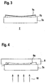
- the construction of the deflecting mirror 7 is shown schematically in FIG.
- the deflecting mirror 7 consists of a base body 7a made of glass and an attachment 7b on diacryl, the curved surface of which is provided with a reflective layer 7c to form the mirror surface.
- the base body 7a made of glass consists of a glass plate with an oval cross-section.
- the glass plate has a flat bottom and top.
- the attachment 7b made of acrylic is applied to the upper side of the glass plate, its upper side having the concave curvature for compensation of the beam distortions of the received light beams 5.
- the attachment extends almost over the entire surface of the glass plate. Only in the edge region of the glass plate whose top is exposed.
- Figure 4 shows schematically the structure of a device for producing the deflecting mirror 7 according to Figure 3.
- a mold 9 is first placed, which has a recess 9a on its underside, which corresponds to the shape of the article to be produced 7b.
- the mold 9 sits with its edges close to the edges of the glass plate. In this way creates a cavity between the edges of the recess and the top of the glass plate.
- liquid diacryl is injected via an insertion, wherein the injection direction is indicated in Figure 4 with an arrow.
- the injected diacryl is then cured with UV light 10, whereby it connects to the glass plate to form the attachment 7b. Then the mold is removed again from the glass plate. Thereafter, the reflective layer can be applied to the curved top of the cap 7b.
- the receiver 6 is preceded by a receiving optics 11 configured as a Cassegrain lens.
- the receiving optics 11 has a concave entrance mirror 12 and a further, the entrance mirror 12 opposite, convexly curved mirror 13.
- the centers of the entrance mirror 12 and the mirror 13 lie in the axis of rotation of the deflecting mirror 7 and are rotationally symmetrical formed on this axis of rotation.
- the entrance mirror 12 has a central, circular bore 14.
- the receiver 6 is behind the bore 14 at a distance from the mirror 13.
- the mirror 13 is formed as a hyperboloid.
- a light trap in the form of an annular opaque web 16 connects.
- the components of the receiving optics 11 are made of injection-molded plastic parts, wherein on the entrance mirror 12 and the mirror 13 to form mirror surfaces reflective layer structures are applied.
- the received light beams 5 reflected at the deflecting mirror 7 are first guided onto the entrance mirror 12 and reflected from there to the mirror 13.
- the light reflected on the mirror 13 received light rays 5 then pass through the tube 15 to the receiver 6.
- Through the tube 15 and the light trap is prevented that stray light, which is not guided over the deflecting mirror 7 but incident obliquely on the receiving optics 11, reaches the receiver 6 ,
- the entrance mirror 12 of the receiving optics 11 also contains a near-field optics, with which received light beams 5, the objects of small distance are arranged to the optical sensor 1, are guided to the receiver.
- a reception signal level sufficient for the object detection is thus also generated in the detection of objects at a very short distance from the optical sensor 1.
- the entrance mirror 12 has three concentrically arranged after-range zones N 1 , N 2 , N 3 which lie between an inner long-range zone F 1 and an outer long-range zone F 2 of the entrance mirror 12.
- the short-range zones N 1 , N 2 , N 3 are formed by annular zones of the entrance mirror 12, each having a predetermined object distance f N1 , f N2 , f N3 , which are smaller than the object lengths f F1 , f F2 of Fem Suiteszonen present Case are the same size.
Landscapes
- Engineering & Computer Science (AREA)
- Physics & Mathematics (AREA)
- Remote Sensing (AREA)
- Computer Networks & Wireless Communication (AREA)
- General Physics & Mathematics (AREA)
- Radar, Positioning & Navigation (AREA)
- Electromagnetism (AREA)
- Optical Radar Systems And Details Thereof (AREA)
- Geophysics And Detection Of Objects (AREA)
- Optical Communication System (AREA)
- Glass Compositions (AREA)
- Investigating Or Analysing Materials By The Use Of Chemical Reactions (AREA)
- Gyroscopes (AREA)
Applications Claiming Priority (1)
| Application Number | Priority Date | Filing Date | Title |
|---|---|---|---|
| DE102004055851A DE102004055851A1 (de) | 2004-11-19 | 2004-11-19 | Optischer Sensor |
Publications (3)
| Publication Number | Publication Date |
|---|---|
| EP1666913A2 true EP1666913A2 (fr) | 2006-06-07 |
| EP1666913A3 EP1666913A3 (fr) | 2007-07-18 |
| EP1666913B1 EP1666913B1 (fr) | 2008-10-15 |
Family
ID=35840342
Family Applications (1)
| Application Number | Title | Priority Date | Filing Date |
|---|---|---|---|
| EP05023918A Expired - Lifetime EP1666913B1 (fr) | 2004-11-19 | 2005-11-03 | Capteur optique |
Country Status (3)
| Country | Link |
|---|---|
| EP (1) | EP1666913B1 (fr) |
| AT (1) | ATE411534T1 (fr) |
| DE (2) | DE102004055851A1 (fr) |
Cited By (7)
| Publication number | Priority date | Publication date | Assignee | Title |
|---|---|---|---|---|
| WO2008061576A1 (fr) | 2006-11-25 | 2008-05-29 | Leuze Electronic Gmbh + Co. Kg | Capteur optique |
| CN102313909A (zh) * | 2010-05-20 | 2012-01-11 | 洛伊策电子两合公司 | 光学传感器 |
| US9964437B2 (en) | 2016-05-03 | 2018-05-08 | Datalogic IP Tech, S.r.l. | Laser scanner with reduced internal optical reflection comprising a light detector disposed between an interference filter and a collecting mirror |
| US10048120B2 (en) | 2016-05-03 | 2018-08-14 | Datalogic IP Tech, S.r.l. | Laser scanner and optical system |
| US10061021B2 (en) | 2016-07-06 | 2018-08-28 | Datalogic IP Tech, S.r.l. | Clutter filter configuration for safety laser scanner |
| US11585905B2 (en) | 2016-05-03 | 2023-02-21 | Datalogic Ip Tech S.R.L. | Laser scanner |
| DE102022129602A1 (de) * | 2022-11-09 | 2024-05-16 | Ifm Electronic Gmbh | Cassegrain-Anordnung für ein optisches Entfernungsmesssystem |
Families Citing this family (2)
| Publication number | Priority date | Publication date | Assignee | Title |
|---|---|---|---|---|
| ES2903096T3 (es) | 2016-12-22 | 2022-03-31 | Vaelinge Innovation Ab | Dispositivo para insertar una lengüeta en una ranura de inserción en un panel |
| EP4166992B1 (fr) * | 2021-10-13 | 2024-11-13 | Leuze electronic GmbH + Co. KG | Capteur optique |
Citations (1)
| Publication number | Priority date | Publication date | Assignee | Title |
|---|---|---|---|---|
| DE9401413U1 (de) | 1994-01-28 | 1994-03-24 | Leuze Electronic Gmbh + Co, 73277 Owen | Gehäuse für eine optoelektronische Vorrichtung |
Family Cites Families (12)
| Publication number | Priority date | Publication date | Assignee | Title |
|---|---|---|---|---|
| DE4340756C5 (de) * | 1992-12-08 | 2006-08-10 | Sick Ag | Laserabstandsermittlungsvorrichtung |
| DE9421457U1 (de) * | 1994-04-08 | 1996-01-04 | Leuze Electronic Gmbh + Co, 73277 Owen | Optoelektronische Vorrichtung zum Erfassen von Gegenständen in einem Überwachungsbereich |
| JP3316312B2 (ja) * | 1994-08-11 | 2002-08-19 | 東海カーボン株式会社 | 走査式放射計 |
| DE19530281C2 (de) * | 1995-08-17 | 1999-01-07 | Johann Hipp | Vorrichtung zum optischen Erfassen von Hindernissen vor Fahrzeugen |
| DE19735037C2 (de) * | 1997-08-13 | 1999-06-02 | Schmersal Eot Gmbh & Co Kg | Vorrichtung zum Orten von in einen zu überwachenden Raumbereich eindringenden Objekten |
| DE19928958A1 (de) * | 1999-05-22 | 2000-11-23 | Volkswagen Ag | Laserscanner |
| DE19928957A1 (de) * | 1999-05-22 | 2000-11-23 | Volkswagen Ag | Empfangseinrichtung für einen Laserscanner |
| DE50014199D1 (de) * | 2000-04-19 | 2007-05-10 | Sick Ag | Vorrichtung zum Orten von in einen zu überwachenden Raumbereich eindringenden Objekten |
| DE10114362C2 (de) * | 2001-03-22 | 2003-12-24 | Martin Spies | Laserscan-System für Entfernungsmessung |
| DE10143060A1 (de) * | 2001-09-03 | 2003-03-20 | Sick Ag | Optoelektronische Erfassungseinrichtung |
| DE10304187A1 (de) * | 2003-01-29 | 2004-08-19 | Iqsun Gmbh | 3D-Scanner |
| DE10326848B4 (de) * | 2003-06-14 | 2005-06-23 | Leuze Lumiflex Gmbh + Co. Kg | Optischer Sensor |
-
2004
- 2004-11-19 DE DE102004055851A patent/DE102004055851A1/de not_active Withdrawn
-
2005
- 2005-11-03 AT AT05023918T patent/ATE411534T1/de active
- 2005-11-03 DE DE502005005678T patent/DE502005005678D1/de not_active Expired - Lifetime
- 2005-11-03 EP EP05023918A patent/EP1666913B1/fr not_active Expired - Lifetime
Patent Citations (1)
| Publication number | Priority date | Publication date | Assignee | Title |
|---|---|---|---|---|
| DE9401413U1 (de) | 1994-01-28 | 1994-03-24 | Leuze Electronic Gmbh + Co, 73277 Owen | Gehäuse für eine optoelektronische Vorrichtung |
Cited By (8)
| Publication number | Priority date | Publication date | Assignee | Title |
|---|---|---|---|---|
| WO2008061576A1 (fr) | 2006-11-25 | 2008-05-29 | Leuze Electronic Gmbh + Co. Kg | Capteur optique |
| US8288706B2 (en) | 2006-11-25 | 2012-10-16 | Leuze Electronic Gmbh & Co. Kg | Optical sensor comprising at least one optical element with a freeform boundary surface |
| CN102313909A (zh) * | 2010-05-20 | 2012-01-11 | 洛伊策电子两合公司 | 光学传感器 |
| US9964437B2 (en) | 2016-05-03 | 2018-05-08 | Datalogic IP Tech, S.r.l. | Laser scanner with reduced internal optical reflection comprising a light detector disposed between an interference filter and a collecting mirror |
| US10048120B2 (en) | 2016-05-03 | 2018-08-14 | Datalogic IP Tech, S.r.l. | Laser scanner and optical system |
| US11585905B2 (en) | 2016-05-03 | 2023-02-21 | Datalogic Ip Tech S.R.L. | Laser scanner |
| US10061021B2 (en) | 2016-07-06 | 2018-08-28 | Datalogic IP Tech, S.r.l. | Clutter filter configuration for safety laser scanner |
| DE102022129602A1 (de) * | 2022-11-09 | 2024-05-16 | Ifm Electronic Gmbh | Cassegrain-Anordnung für ein optisches Entfernungsmesssystem |
Also Published As
| Publication number | Publication date |
|---|---|
| EP1666913B1 (fr) | 2008-10-15 |
| DE102004055851A1 (de) | 2006-05-24 |
| EP1666913A3 (fr) | 2007-07-18 |
| ATE411534T1 (de) | 2008-10-15 |
| DE502005005678D1 (de) | 2008-11-27 |
Similar Documents
| Publication | Publication Date | Title |
|---|---|---|
| EP0843180B1 (fr) | Télémétrie | |
| DE10326848B4 (de) | Optischer Sensor | |
| EP2296002B1 (fr) | Scanner optoélectronique pour la détermination de distances en azimut et élévation | |
| EP2238469B1 (fr) | Dispositif de détermination d'une distance à un objet | |
| EP1421410B1 (fr) | Dispositif de mesure a distance | |
| EP1289796B1 (fr) | Unite de detection photosensible, notamment pour la commutation automatique de dispositifs d'eclairage | |
| DE4412044A1 (de) | Optoelektronische Vorrichtung zum Erfassen von Gegenständen in einem Überwachungsbereich | |
| DE19706612C2 (de) | Optoelektronische Vorrichtung | |
| DE19732776C1 (de) | Optoelektronische Vorrichtung | |
| EP1666913B1 (fr) | Capteur optique | |
| EP1160718B1 (fr) | Appareil à balayage laser | |
| EP2101196B1 (fr) | Capteur optique avec concentrateur de lumière | |
| EP1515157A1 (fr) | Dispositif de détection optoélectronique | |
| EP1202886A1 (fr) | Dispositif detecteur pour la detection du mouillage sur une vitre | |
| EP1624322B1 (fr) | Capteur optique | |
| DE102016106154B3 (de) | Optoelektronischer Sensor und Verfahren zur Erfassung und Entfernungsbestimmung eines Objekts | |
| DE102018104787A1 (de) | Optoelektronischer Sensor und Herstellungsverfahren für eine Frontscheibe | |
| DE10308085A1 (de) | Optoelektronische Vorrichtung | |
| DE19707418C2 (de) | Optoelektronische Vorrichtung | |
| DE9421457U1 (de) | Optoelektronische Vorrichtung zum Erfassen von Gegenständen in einem Überwachungsbereich | |
| EP3546980A1 (fr) | Capteur optique | |
| EP3699637B1 (fr) | Capteur optoélectronique et procédé de détection d'un objet | |
| DE10034555A1 (de) | Lichtempfindliche Sensoreinheit, insbesondere zum automatischen Schalten von Beleuchtungseinrichtungen | |
| EP2653883B1 (fr) | Capteur optique | |
| DE10209269C1 (de) | Optoelektronische Vorrichtung |
Legal Events
| Date | Code | Title | Description |
|---|---|---|---|
| PUAI | Public reference made under article 153(3) epc to a published international application that has entered the european phase |
Free format text: ORIGINAL CODE: 0009012 |
|
| AK | Designated contracting states |
Kind code of ref document: A2 Designated state(s): AT BE BG CH CY CZ DE DK EE ES FI FR GB GR HU IE IS IT LI LT LU LV MC NL PL PT RO SE SI SK TR |
|
| AX | Request for extension of the european patent |
Extension state: AL BA HR MK YU |
|
| PUAL | Search report despatched |
Free format text: ORIGINAL CODE: 0009013 |
|
| AK | Designated contracting states |
Kind code of ref document: A3 Designated state(s): AT BE BG CH CY CZ DE DK EE ES FI FR GB GR HU IE IS IT LI LT LU LV MC NL PL PT RO SE SI SK TR |
|
| AX | Request for extension of the european patent |
Extension state: AL BA HR MK YU |
|
| 17P | Request for examination filed |
Effective date: 20070713 |
|
| 17Q | First examination report despatched |
Effective date: 20070822 |
|
| AKX | Designation fees paid |
Designated state(s): AT CH DE FR GB IT LI |
|
| GRAP | Despatch of communication of intention to grant a patent |
Free format text: ORIGINAL CODE: EPIDOSNIGR1 |
|
| GRAS | Grant fee paid |
Free format text: ORIGINAL CODE: EPIDOSNIGR3 |
|
| GRAA | (expected) grant |
Free format text: ORIGINAL CODE: 0009210 |
|
| AK | Designated contracting states |
Kind code of ref document: B1 Designated state(s): AT CH DE FR GB IT LI |
|
| REG | Reference to a national code |
Ref country code: GB Ref legal event code: FG4D Free format text: NOT ENGLISH Ref country code: CH Ref legal event code: NV Representative=s name: ROTTMANN, ZIMMERMANN + PARTNER AG Ref country code: CH Ref legal event code: EP |
|
| REF | Corresponds to: |
Ref document number: 502005005678 Country of ref document: DE Date of ref document: 20081127 Kind code of ref document: P |
|
| PLBE | No opposition filed within time limit |
Free format text: ORIGINAL CODE: 0009261 |
|
| STAA | Information on the status of an ep patent application or granted ep patent |
Free format text: STATUS: NO OPPOSITION FILED WITHIN TIME LIMIT |
|
| 26N | No opposition filed |
Effective date: 20090716 |
|
| REG | Reference to a national code |
Ref country code: CH Ref legal event code: PFA Owner name: LEUZE ELECTRONIC GMBH + CO KG Free format text: LEUZE ELECTRONIC GMBH + CO KG#IN DER BRAIKE 1#73277 OWEN/TECK (DE) -TRANSFER TO- LEUZE ELECTRONIC GMBH + CO KG#IN DER BRAIKE 1#73277 OWEN/TECK (DE) |
|
| PGFP | Annual fee paid to national office [announced via postgrant information from national office to epo] |
Ref country code: FR Payment date: 20131120 Year of fee payment: 9 Ref country code: AT Payment date: 20131113 Year of fee payment: 9 Ref country code: GB Payment date: 20131120 Year of fee payment: 9 |
|
| REG | Reference to a national code |
Ref country code: AT Ref legal event code: MM01 Ref document number: 411534 Country of ref document: AT Kind code of ref document: T Effective date: 20141103 |
|
| GBPC | Gb: european patent ceased through non-payment of renewal fee |
Effective date: 20141103 |
|
| REG | Reference to a national code |
Ref country code: FR Ref legal event code: ST Effective date: 20150731 |
|
| PG25 | Lapsed in a contracting state [announced via postgrant information from national office to epo] |
Ref country code: AT Free format text: LAPSE BECAUSE OF NON-PAYMENT OF DUE FEES Effective date: 20141103 |
|
| PG25 | Lapsed in a contracting state [announced via postgrant information from national office to epo] |
Ref country code: GB Free format text: LAPSE BECAUSE OF NON-PAYMENT OF DUE FEES Effective date: 20141103 |
|
| PG25 | Lapsed in a contracting state [announced via postgrant information from national office to epo] |
Ref country code: FR Free format text: LAPSE BECAUSE OF NON-PAYMENT OF DUE FEES Effective date: 20141201 |
|
| REG | Reference to a national code |
Ref country code: CH Ref legal event code: PCAR Free format text: NEW ADDRESS: GARTENSTRASSE 28 A, 5400 BADEN (CH) |
|
| PGFP | Annual fee paid to national office [announced via postgrant information from national office to epo] |
Ref country code: DE Payment date: 20181115 Year of fee payment: 14 |
|
| PGFP | Annual fee paid to national office [announced via postgrant information from national office to epo] |
Ref country code: CH Payment date: 20181120 Year of fee payment: 14 Ref country code: IT Payment date: 20181126 Year of fee payment: 14 |
|
| REG | Reference to a national code |
Ref country code: DE Ref legal event code: R119 Ref document number: 502005005678 Country of ref document: DE |
|
| REG | Reference to a national code |
Ref country code: CH Ref legal event code: PL |
|
| PG25 | Lapsed in a contracting state [announced via postgrant information from national office to epo] |
Ref country code: LI Free format text: LAPSE BECAUSE OF NON-PAYMENT OF DUE FEES Effective date: 20191130 Ref country code: CH Free format text: LAPSE BECAUSE OF NON-PAYMENT OF DUE FEES Effective date: 20191130 |
|
| PG25 | Lapsed in a contracting state [announced via postgrant information from national office to epo] |
Ref country code: DE Free format text: LAPSE BECAUSE OF NON-PAYMENT OF DUE FEES Effective date: 20200603 Ref country code: IT Free format text: LAPSE BECAUSE OF NON-PAYMENT OF DUE FEES Effective date: 20191103 |