EP1666964A2 - Support électrophorétique avec stabilité d'image améliorée - Google Patents
Support électrophorétique avec stabilité d'image améliorée Download PDFInfo
- Publication number
- EP1666964A2 EP1666964A2 EP06002515A EP06002515A EP1666964A2 EP 1666964 A2 EP1666964 A2 EP 1666964A2 EP 06002515 A EP06002515 A EP 06002515A EP 06002515 A EP06002515 A EP 06002515A EP 1666964 A2 EP1666964 A2 EP 1666964A2
- Authority
- EP
- European Patent Office
- Prior art keywords
- polymer
- medium
- electrophoretic
- particles
- suspending fluid
- Prior art date
- Legal status (The legal status is an assumption and is not a legal conclusion. Google has not performed a legal analysis and makes no representation as to the accuracy of the status listed.)
- Granted
Links
Images







Classifications
-
- G—PHYSICS
- G09—EDUCATION; CRYPTOGRAPHY; DISPLAY; ADVERTISING; SEALS
- G09G—ARRANGEMENTS OR CIRCUITS FOR CONTROL OF INDICATING DEVICES USING STATIC MEANS TO PRESENT VARIABLE INFORMATION
- G09G3/00—Control arrangements or circuits, of interest only in connection with visual indicators other than cathode-ray tubes
- G09G3/20—Control arrangements or circuits, of interest only in connection with visual indicators other than cathode-ray tubes for presentation of an assembly of a number of characters, e.g. a page, by composing the assembly by combination of individual elements arranged in a matrix no fixed position being assigned to or needed to be assigned to the individual characters or partial characters
- G09G3/34—Control arrangements or circuits, of interest only in connection with visual indicators other than cathode-ray tubes for presentation of an assembly of a number of characters, e.g. a page, by composing the assembly by combination of individual elements arranged in a matrix no fixed position being assigned to or needed to be assigned to the individual characters or partial characters by control of light from an independent source
- G09G3/3433—Control arrangements or circuits, of interest only in connection with visual indicators other than cathode-ray tubes for presentation of an assembly of a number of characters, e.g. a page, by composing the assembly by combination of individual elements arranged in a matrix no fixed position being assigned to or needed to be assigned to the individual characters or partial characters by control of light from an independent source using light modulating elements actuated by an electric field and being other than liquid crystal devices and electrochromic devices
- G09G3/344—Control arrangements or circuits, of interest only in connection with visual indicators other than cathode-ray tubes for presentation of an assembly of a number of characters, e.g. a page, by composing the assembly by combination of individual elements arranged in a matrix no fixed position being assigned to or needed to be assigned to the individual characters or partial characters by control of light from an independent source using light modulating elements actuated by an electric field and being other than liquid crystal devices and electrochromic devices based on particles moving in a fluid or in a gas, e.g. electrophoretic devices
-
- G—PHYSICS
- G02—OPTICS
- G02F—OPTICAL DEVICES OR ARRANGEMENTS FOR THE CONTROL OF LIGHT BY MODIFICATION OF THE OPTICAL PROPERTIES OF THE MEDIA OF THE ELEMENTS INVOLVED THEREIN; NON-LINEAR OPTICS; FREQUENCY-CHANGING OF LIGHT; OPTICAL LOGIC ELEMENTS; OPTICAL ANALOGUE/DIGITAL CONVERTERS
- G02F1/00—Devices or arrangements for the control of the intensity, colour, phase, polarisation or direction of light arriving from an independent light source, e.g. switching, gating or modulating; Non-linear optics
- G02F1/01—Devices or arrangements for the control of the intensity, colour, phase, polarisation or direction of light arriving from an independent light source, e.g. switching, gating or modulating; Non-linear optics for the control of the intensity, phase, polarisation or colour
- G02F1/165—Devices or arrangements for the control of the intensity, colour, phase, polarisation or direction of light arriving from an independent light source, e.g. switching, gating or modulating; Non-linear optics for the control of the intensity, phase, polarisation or colour based on translational movement of particles in a fluid under the influence of an applied field
- G02F1/166—Devices or arrangements for the control of the intensity, colour, phase, polarisation or direction of light arriving from an independent light source, e.g. switching, gating or modulating; Non-linear optics for the control of the intensity, phase, polarisation or colour based on translational movement of particles in a fluid under the influence of an applied field characterised by the electro-optical or magneto-optical effect
- G02F1/167—Devices or arrangements for the control of the intensity, colour, phase, polarisation or direction of light arriving from an independent light source, e.g. switching, gating or modulating; Non-linear optics for the control of the intensity, phase, polarisation or colour based on translational movement of particles in a fluid under the influence of an applied field characterised by the electro-optical or magneto-optical effect by electrophoresis
-
- G—PHYSICS
- G02—OPTICS
- G02F—OPTICAL DEVICES OR ARRANGEMENTS FOR THE CONTROL OF LIGHT BY MODIFICATION OF THE OPTICAL PROPERTIES OF THE MEDIA OF THE ELEMENTS INVOLVED THEREIN; NON-LINEAR OPTICS; FREQUENCY-CHANGING OF LIGHT; OPTICAL LOGIC ELEMENTS; OPTICAL ANALOGUE/DIGITAL CONVERTERS
- G02F2202/00—Materials and properties
- G02F2202/02—Materials and properties organic material
- G02F2202/022—Materials and properties organic material polymeric
-
- G—PHYSICS
- G09—EDUCATION; CRYPTOGRAPHY; DISPLAY; ADVERTISING; SEALS
- G09G—ARRANGEMENTS OR CIRCUITS FOR CONTROL OF INDICATING DEVICES USING STATIC MEANS TO PRESENT VARIABLE INFORMATION
- G09G2320/00—Control of display operating conditions
- G09G2320/02—Improving the quality of display appearance
- G09G2320/0233—Improving the luminance or brightness uniformity across the screen
-
- G—PHYSICS
- G09—EDUCATION; CRYPTOGRAPHY; DISPLAY; ADVERTISING; SEALS
- G09G—ARRANGEMENTS OR CIRCUITS FOR CONTROL OF INDICATING DEVICES USING STATIC MEANS TO PRESENT VARIABLE INFORMATION
- G09G2320/00—Control of display operating conditions
- G09G2320/02—Improving the quality of display appearance
- G09G2320/0252—Improving the response speed
-
- G—PHYSICS
- G09—EDUCATION; CRYPTOGRAPHY; DISPLAY; ADVERTISING; SEALS
- G09G—ARRANGEMENTS OR CIRCUITS FOR CONTROL OF INDICATING DEVICES USING STATIC MEANS TO PRESENT VARIABLE INFORMATION
- G09G2330/00—Aspects of power supply; Aspects of display protection and defect management
- G09G2330/02—Details of power systems and of start or stop of display operation
- G09G2330/021—Power management, e.g. power saving
Definitions
- This invention relates to an electrophoretic medium with improved image stability, and to an electrophoretic display including this medium. More specifically, this invention relates to an electrophoretic medium and display which allow improved image stability without unacceptable increases in the switching time or the drive voltage of the display.
- Electrophoretic displays have been the subject of intense research and development for a number of years. Such displays can have attributes of good brightness and contrast, wide viewing angles, state bistability, and low power consumption when compared with liquid crystal displays.
- bistable and “bistability” are used herein in their conventional meaning in the art to refer to displays comprising display elements having first and second display states differing in at least one optical property, and such that after any given element has been driven, by means of an addressing pulse of finite duration, to assume either its first or second display state, after the addressing pulse has terminated, that state will persist for at least several times, for example at least four times, the minimum duration of the addressing pulse required to change the state of the display element.
- some electrophoretic displays are capable of achieving multiple gray states, and, as demonstrated below, are stable not only in their extreme black and white optical states, but also in their intermediate gray states. Although such displays should properly be described as “multi-stable” rather than “bistable”, the latter term may be used herein for convenience.
- the optical property which is changed by application of an electric field is typically color perceptible to the human eye, but may be another optical property, such as optical transmission, reflectance, luminescence or, in the case of displays intended for machine reading, pseudo-color in the sense of a change in reflectance of electromagnetic wavelengths outside the visible range. Nevertheless, problems with the long-term image quality of these displays have prevented their widespread usage. For example, particles that make up electrophoretic displays tend to settle, resulting in inadequate service-life for these displays.
- encapsulated electrophoretic media comprise numerous small capsules, each of which itself comprises an internal phase containing electrophoretically-mobile particles suspended in a liquid suspension medium, and a capsule wall surrounding the internal phase.
- the capsules are themselves held within a polymeric binder to form a coherent layer positioned between two electrodes.
- Encapsulated media of this type are described, for example, in U.S. Patents Nos.
- An encapsulated, electrophoretic display typically does not suffer from the clustering and settling failure mode of traditional electrophoretic devices and provides further advantages, such as the ability to print or coat the display on a wide variety of flexible and rigid substrates.
- printing is intended to include all forms of printing and coating, including, but without limitation: pre-metered coatings such as patch die coating, slot or extrusion coating, slide or cascade coating, curtain coating; roll coating such as knife over roll coating, forward and reverse roll coating; gravure coating; dip coating; spray coating; meniscus coating; spin coating; brush coating; air knife coating; silk screen printing processes; electrostatic printing processes; thermal printing processes; ink jet printing processes; and other similar techniques.
- pre-metered coatings such as patch die coating, slot or extrusion coating, slide or cascade coating, curtain coating
- roll coating such as knife over roll coating, forward and reverse roll coating
- gravure coating dip coating
- spray coating meniscus coating
- spin coating spin coating
- brush coating air knife coating
- silk screen printing processes electrostatic printing processes
- electrophoretic displays exhibit bistability, this bistability is not unlimited, and images on the display slowly fade with time, so that if an image is to be maintained for extended periods, the image must be refreshed periodically (and the intervals at which such refreshing is necessary is a convenient quantitative measure of image stability).
- the electrophoretic mobility of the pigment particles (the rate at which the particles move through the liquid phase under a given electric field) is also inversely proportional to the viscosity of the liquid phase, and thus the switching time of the display (the time required to change a given pixel of the display from one of its optical states to the other - essentially the time necessary for the pigment particles to move through the thickness of the liquid medium) is directly proportional to the viscosity of the liquid medium.
- any chosen viscosity necessarily represents a compromise, in that increasing the viscosity will increase image stability at the cost of increased switching time.
- users will not tolerate switching times substantially in excess of about 1 second. (Although it is possible to counteract an increase in switching time due to increased viscosity of the suspending fluid by increasing the drive voltage applied to the display, this brings its own set of problems.
- this invention provides an electrophoretic medium comprising a plurality of particles suspended in a suspending fluid, the particles being capable of moving through the fluid upon application of an electric field to the medium.
- the medium of the present invention is characterized in that the fluid has dissolved or dispersed therein a polymer having a number average molecular weight in excess of 20,000, the polymer being essentially non-absorbing on the particles.
- the polymer is a polyisobutylene having a viscosity average molecular weight in the range of 200,000 to 1,600,000 g/mole, the polyisobutylene comprising from 0.25 to 2.5 per cent by weight of the suspending fluid.
- This invention also provides an electrophoretic medium comprising a plurality of particles suspended in a suspending fluid, the particles being capable of moving through the fluid upon application of an electric field to the medium.
- the fluid has dissolved or dispersed therein a polymer having an intrinsic viscosity of [ ⁇ ] in the suspending fluid and being substantially free from ionic or ionizable groups in the suspending fluid, the polymer being present in the suspending fluid in a concentration of from 0.5 [ ⁇ ] -1 to 2.0 [ ⁇ ] -1 .
- the present invention provides an electrophoretic medium comprising a plurality of particles suspended in a suspending fluid.
- the particles are capable of moving through the fluid upon application of an electric field to the medium.
- the fluid contains a dissolved and/or dispersed polymer having a number average molecular weight in excess of about 20,000, this polymer being essentially non-absorbing on the particles.
- the electrophoretic medium of the present invention may be of any of the types described in the aforementioned E Ink and MIT patents and applications, and preferred embodiments of such media will now be described with reference to Figures 1 to 3 of the accompanying drawings.
- the first electrophoretic display (generally designed 100) of the invention shown in Figures 1A and 1B comprises an encapsulated electrophoretic medium (generally designated 102) comprising a plurality of capsules 104 (only one of which is shown in Figures 1A-1C), each of which contains a suspending liquid 106 and dispersed therein a plurality of a single type of particle 108, which for purposes of illustration will be assumed to be black.
- the particles 108 are electrophoretically mobile and may be formed of carbon black. In the following description, it will be assumed that the particles 108 are positively charged, although of course negatively charged particles could also be used if desired.
- the display 100 further comprises a common, transparent front electrode 110, which forms a viewing surface through which an observer views the display 100, and a plurality of discrete rear electrodes 112, each of which defines one pixel of the display 100 (only one rear electrode 112 is shown in Figures 1A and 1B).
- Figures 1A and 1B show only a single microcapsule forming the pixel defined by rear electrode 112, although in practice a large number (20 or more) microcapsules are normally used for each pixel.
- the rear electrodes 112 are mounted upon a substrate 114.
- the suspending liquid 106 is colored such that the particles 108 lying in the positions shown in Figure 1A adjacent the rear electrodes 112 are not visible to an observer viewing the display 100 via the front electrode 110.
- the necessary color in the suspending liquid 106 may be provided by dissolving a dye in the liquid. Since the colored suspending liquid 106 and the particles 108 render the electrophoretic medium 102 opaque, the rear electrodes 112 and the substrate 114 can be transparent or opaque since they are not visible through the opaque electrophoretic medium 102.
- the capsules 104 and the particles 108 can be made in a wide range of sizes. However, in general it is preferred that the thickness of the capsules, measured perpendicular to the electrodes, be in the range of about 10 to 500 ⁇ m, while the particles 108 will typically have diameters in the range of about 0.25 to about 2 ⁇ m.
- Figure 1A shows the display 100 with the rear electrode 112 negatively charged and the front electrode 110 positively charged. Under this condition, the positively-charged particles 108 are attracted to the negative rear electrode 112 and thus lie adjacent the rear electrode 112, where they are hidden from an observer viewing the display 100 through the front electrode 110 by the colored liquid 106. Accordingly, the pixel shown in Figure 1A displays to the observer the color of the liquid 106, which for purposes of illustration will be assumed to be white. (Although the display 100 is illustrated in Figures 1A and 1B with the rear electrodes 112 at the bottom, in practice both the front and rear electrodes are typically disposed vertically for maximum visibility of the display 100. None of the specific embodiments of the invention described herein rely in any way upon gravity to control the movement of the particles; such movement under gravity is in practice far too slow to be useful for controlling particle movement.)
- Figure 1B shows the display 100 with the front electrode 110 made negative relative to the rear electrode 112. Since the particles 108 are positively charged, they will be attracted to the negatively-charged front electrode 110, and thus the particles 108 move adjacent the front electrode 110, and the pixel displays the black color of the particles 108.
- the capsules 104 are illustrated as being of substantially prismatic form, having a width (parallel to the planes of the electrodes) significantly greater than their height (perpendicular to these planes).
- This prismatic shape of the capsules 104 is deliberate. If the capsules 104 were essentially spherical, in the black state shown in Figure 1B, the particles 108 would tend to gather in the highest part of the capsule, in a limited area centered directly above the center of the capsule. The color seen by the observer would then be essentially the average of this central black area and a white annulus surrounding this central area, where the white liquid 106 would be visible.
- microcapsules are normally embedded within a solid binder, but this binder is omitted from Figures 1 to 3 for ease of illustration.
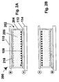
- the second electrophoretic display (generally designed 200) of the invention shown in Figures 2A and 2B comprises an encapsulated electrophoretic medium (generally designated 202) comprising a plurality of capsules 204, each of which contains a suspending liquid 206 and dispersed therein a plurality of positively charged black particles 108 identical discussed to those in the first display 100 discussed above.
- the display 200 further comprises a front electrode 110, rear electrodes 112, and a substrate 114, all of which are identical to the corresponding integers in the first display 100.
- the black particles 108 there are suspended in the liquid 206 a plurality of negatively charged, particles 218, which for present purposes will be assumed to be white.
- FIG. 2A shows the display 200 with the front electrode 110 positively charged relative to the rear electrode 112 of the illustrated pixel.
- the positively charged particles 108 are held electrostatically adjacent the rear electrode 112, while the negatively charged particles 218 are held electrostatically against the front electrode 110. Accordingly, an observer viewing the display 200 through the front electrode 110 sees a white pixel, since the white particles 218 are visible and hide the black particles 108.
- Figure 2B shows the display 200 with the front electrode 110 negatively charged relative to the rear electrode 112 of the illustrated pixel.
- the positively charged particles 108 are now electrostatically attracted to the negative front electrode 110, while the negatively charged particles 218 are electrostatically attracted to the positive rear electrode 112. Accordingly, the particles 108 move adjacent the front electrode 110, and the pixel displays the black color of the particles 108, which hide the white particles 218.
- the third electrophoretic display (generally designated 300) of the invention shown in Figures 3A and 3B comprises an encapsulated electrophoretic medium (generally designated 302) comprising a plurality of capsules 304.
- the display 300 further comprises a front electrode 110, rear electrodes 112, and a substrate 114, all of which are identical to the corresponding integers in the displays 100 and 200 previously described.
- the display 300 resembles the display 200 described above in that the liquid 306 is uncolored and that white negatively charged particles 218 are suspended therein. However, that the display 300 differs from the display 200 by the presence of red negatively charged particles 320, which have a substantially lower electrophoretic mobility than the white particles 218.
- Figure 3A shows the display 300 with the front electrode 110 positively charged relative to the rear electrode 112 of the illustrated pixel.
- Both the negatively charged white particles 218 and the negatively charged red particles 320 are attracted to the front electrode 110, but since the white particles 218 have substantially higher electrophoretic mobility, they reach the front electrode 110 first (note that the optical state shown in Figure 3A is normally generated by abruptly reversing the polarity of the electrodes in the optical state shown in Figure 3B, thus forcing both the white particles 218 and the red particles 320 to traverse the thickness of the capsule 304, and thus allowing the greater mobility of the white particles 218 to cause them to reach their positions adjacent the front electrode 110 before the red particles 320).
- the white particles 218 form a continuous layer immediately adjacent the front electrode 110, thereby hiding the red particles 320. Accordingly, an observer viewing the display 300 through the front electrode 110 sees a white pixel, since the white particles 218 are visible and hide the red particles 320.
- Figure 3B shows the display 300 with the front electrode 110 negatively charged relative to the rear electrode 112 of the illustrated pixel.
- Both the negatively charged white particles 218 and the negatively charged red particles 320 are attracted to the rear electrode 112, but since the white particles have higher electrophoretic mobility, when the optical state shown in Figure 3B is produced by reversing the polarity on the electrodes in the optical state shown in Figure 3A, the white particles 218 reach the rear electrode 112 more quickly than do the red particles 320, so that the white particles 218 form a continuous layer adjacent the electrode 112, leaving a continuous layer of the red particles 320 facing the front electrode 110. Accordingly, an observer viewing the display 300 through the front electrode 110 sees a red pixel, since the red particles 320 are visible and hide the white particles 218.
- the present invention may be applied to any of the forms of encapsulated electrophoretic media shown in Figures 1 to 3.
- the present invention is not restricted to encapsulated electrophoretic media, and may also be applied to unencapsulated media and to polymer-dispersed electrophoretic media which, as previously described, are of a two-phase type, with the suspending fluid and particles forming a discontinuous phase comprising a plurality of droplets, the droplets being surrounded by a continuous phase.
- the droplets desirably comprise at least about 40 percent by volume all of the electrophoretic medium; see the aforementioned copending Application Serial No. 09/683,903.
- the polymer used in the present medium is very different from certain low molecular weight polymers used as charge control agents in certain prior art electrophoretic media.
- charge control agents are polymer-based (and not all are), they normally have molecular weights of only a few thousand at most, and, more importantly, must have functional groups which cause them to be absorbed on to the electrophoretic particles, since it is only by such absorption that they can exert their function of controlling the charge on the particles.
- the polymer and suspending fluid combination should desirably be such that the fluid is at least a theta solvent for the polymer at room temperature. In order to extend the temperature range of the enhanced image stability, it is optimal if the fluid is at least a moderately good to good solvent for the image stability polymer.
- One method of choosing an appropriate polymer/fluid combination is to plot the intrinsic viscosity of the combination against the molecular weight of the polymer; desirable combinations are those in which the slope of a best linear fit of the log of the intrinsic viscosity against the log of the molecular weight is at least 0.5, and desirably in the range of about 0.55 to about 0.8.
- the suspending fluid used in electrophoretic displays is an aliphatic hydrocarbon (alone or in combination with a halogenated hydrocarbon) and with such fluids, it is preferred that the polymer be a hydrocarbon polymer essentially free from functional groups, such as ionizable or ionic substituents, that may cause the polymer to interact with chemical sites on the electrophoretic particles, or to physically adsorb to the surfaces of the electrophoretic particles.
- functional groups such as ionizable or ionic substituents
- the presence of a substantial proportion of aromatic groups causes poor solubility or adsorption of a polymer onto the electrophoretic particles when the suspending fluid is an equal part by weight mixture of an aliphatic hydrocarbon and halogenated hydrocarbon, so that for this suspending fluid a hydrocarbon copolymer containing a significant fraction of polystyrene repeating units should not be used in such an electrophoretic medium.
- the polymer is preferably a polyolefin, polyisobutylene (poly-2-methylpropene) being the presently preferred polymer, although a variety of other types of polymers for example polysiloxanes, and in particular polydimethylsiloxane, may also be used.
- Polyisobutylene is commercially available in molecular weight ranges appropriate for use in the present invention, inexpensive, stable at high temperatures, resistant to oxidation and does not contain easily reactive or ionizable components.
- the polyisobutylene desirably has a number average molecular weight in excess of 100,000, and preferably in the range of about 150,000 to about 3,000,000, and a weight average molecular weight in excess of 100,000 and preferably in the range of about 300,000 to about 3,000,000; similar molecular weight ranges may be used with other polymers. Polyisobutylenes falling within these molecular weight ranges are readily available commercially, for example from Sigma-Aldrich, Inc., P.O. Box 2060, Milwaukee WI 53201 under catalogue numbers 18145-5 and 18146-3. The polyisobutylene also desirably has a viscosity average molecular weight in the range of about 200,000 to 1,600,000 g/mole.
- the optimum amount of polymer for producing stability in any specific system can readily be determined empirically. As shown in the Examples below, the optimum amount of polymer varies in a rather complicated manner with the degree of image stability required, the molecular weight of the polymer, and the maximum switching time of the medium which can be tolerated. However, by way of general guidance it may be stated that, at least in the case of the preferred polyisobutylenes described above, it is desirable that the polymer be added in an amount of from about 0.25 to about 2.5 per cent by weight of the suspending fluid, and preferably in an amount of about 0.75 to about 2 per cent by weight.
- the polymer produces little or no increase in image stability other than that attributable to the increase in the viscosity of the suspending fluid, while polymer concentrations above about 2.5 per cent cause an increase in viscosity which may render switching times unacceptable.
- the present invention is capable of improving the image stability of electrophoretic media by several orders of magnitude, while increasing the switching time of the media by a factor of only about 2 to 4.
- preferred media of the present invention can achieve image stabilities of at least about 1,000, and in some cases at least about 10,000 seconds or substantially more, whereas similar media without the polymer addition only achieve image stabilities of the order of 10 seconds.
- All reference to image stability times herein are to such times as measured by the time required for L* of an optical state to change by 2 units, as described in Example 1 below.
- the addition of polymer to the suspending fluid in accordance with the present invention has been found to stabilize not only the two extreme optical states of the medium (for example, black and white) but also intermediate gray optical states; as is well known to those skilled in the technology of electrophoretic displays, such gray states can be produced by subjecting the medium to electric pulses of reduced length and/or voltage as compared with the pulses needed to drive the medium from one extreme optical state to the other.
- This ability of the present invention to stabilize gray states is important since it is desirable to use an electrophoretic display capable of gray scale in small displays (such as those used in PDA's) where the limited number of pixels in the display renders areal modulation ("half-toning") to achieve gray scale impracticable.
- the improved image stability achieved by the present invention is not significantly affected by temperature, at least within the working temperatures ranges of the media tested in the Examples below.
- the optical states of electrophoretic media vary with temperature, the period during which the initial state of the medium immediately after a change in optical states persists is not itself significantly affected by the temperature, as shown in Example 5 below.
- the electrophoretic media of the present invention may be incorporated into any known type of electrophoretic display, including any of the types of display described in the aforementioned E Ink and MIT patents and published applications.
- the present invention provides an electrophoretic display comprising an electrophoretic medium of the present invention and at least one electrode arranged adjacent the medium and capable of applying an electric field to the medium.
- Such a display may have a second electrode in the form of a stylus or similar device capable of being moved across the medium to write thereon.
- two electrodes are disposed on opposed sides of the electrophoretic medium, at least one of the electrodes being substantially transparent such that the electrophoretic medium can be viewed through the substantially transparent electrode.
- the electrophoretic medium of the present invention is encapsulated, typically the capsules are held within a solid binder, and one or both electrodes of the display may be secured to the binder by any convenient method, such as hot lamination.
- the suspension medium used in Media A and B was a mixture of a hydrocarbon (Isopar-G, available commercially from Exxon Corporation, Houston, Texas; "Isopar” is a Registered Trade Mark) and a halogenated hydrocarbon oil (Halogenated hydrocarbon oil 1.8, available commercially from Halogenated Hydrocarbon Products Corporation, River Edge, New Jersey - referred to hereinafter for simplicity as "Halocarbon”) containing a dispersant (Solsperse 17000, available commercially from Avecia Ltd., Blackley, Manchester, United Kingdom; “Solsperse” is a Registered Trade Mark).
- Medium C uses no Halocarbon in the suspending fluid.
- Medium A precursor was prepared by combining 40.4 g of polymer-coated titania with 4.1 g of charging agent (Solsperse 17000), 4.1 g of surfactant (Span85), and 123 g of 1:1 w/w Isopar/Halocarbon solvent. This dispersion was mixed overnight and then sonicated for approximately 1 to 2 hours. In a separate jar, 1.7 g of polymer-coated carbon black was combined with 123 g of 1:1 w/w Isopar/Halocarbon solvent; this dispersion was also mixed overnight and then sonicated for 1 to 2 hours.
- the titania and carbon black dispersions were then combined and diluted with 246 g of 1:1 w/w Isopar/Halocarbon solvent.
- Medium A internal phase was prepared by diluting the Medium A precursor with equal mass of 1:1 w/w Isopar/Halocarbon solvent.
- the final dilution solvent was prepared with the appropriate concentration of polyisobutylene.
- the procedure defined above was followed with Isopar V substituted for Isopar G.
- gelatin 22.5 g was dissolved in deionized water (1311.2 g) at 40°C with stirring, care being taken to ensure that no foam was produced on the surface of the solution.
- acacia (16.7 g - available from Sigma-Aldrich) was dissolved in deionized water (327.8 g) and the resultant solution heated to 40°C.
- the internal phase described above (580 g) was heated to 40°C and then added, over a period of approximately 15 minutes to the gelatin solution; the gelatin solution was stirred during the addition, which was conducted by introducing the internal phase through a dropping funnel the outlet of which was placed below the surface of the gelatin solution.
- the rate of stirring was increased and the stirring continued for 30 minutes at 40°C in order to emulsify the internal phase into droplets having an average diameter of about 200 ⁇ m for Medium A and about 80 ⁇ m for Medium B.
- the acacia solution was then added over a period of about 1 minute, care being taken to avoid foaming.
- the pH of the mixture was lowered to approximately 4.9 using 10 per cent aqueous acetic acid, and the vigorous stirring was continued to a further 40 minutes at the same temperature.
- the temperature of the mixture was lowered to 10°C over a period of two hours, with continued vigorous stirring, and glutaraldehyde (8.35 g) was added. After this addition, the mixture was gradually warmed to 25°C and stirred vigorously for a further 12 hours. Finally, stirring was discontinued, and the mixture was allowed to settle for 10-15 minutes, during which time approximately 25-50 mm of a foamy mixture separated on top of the liquid.
- the liquid phase was then removed, leaving the foamy mixture in the reactor, and the capsules in this liquid phase washed three times by sedimentation and redispersion in deionized water.
- Medium A capsules were separated by size to yield a distribution between 100 and 300 ⁇ m diameter, with a mean diameter of about 200 ⁇ m.
- Medium B capsules were separated by size to yield a distribution between 50 and 120 ⁇ m diameter, with a mean diameter of 70-80 ⁇ m; such a distribution can be effected by sieving the capsules for 90 seconds on a 63 ⁇ m sieve and then for 30 seconds on a 38 ⁇ m sieve to produce the final capsule slurry.
- the resulting capsule slurry was centrifuged and then mixed with an aqueous urethane binder (NeoRez R-9320, available from NeoResins, 730 Main Street, Wilmington MA 01887; "NeoRez” is a Registered Trade Mark) at a ratio of 1 part by weight binder to 9 parts by weight of capsules, and 0.3 weight per cent of hydroxypropylmethylcellulose was added as a slot-coating additive.
- the resultant mixture was slot coated on to a 125 ⁇ m thick indium-tin oxide coated polyester film moving at 1 m/sec relative to the slot coating head. The coated film was allowed to air dry for 10 minutes, then oven dried at 50°C for 15 minutes to produce an electrophoretic medium approximately 50 ⁇ m thick containing essentially a single layer of capsules (see the aforementioned published International Patent Application WO 00/20922).
- the capsule-coated surface of the coated film was then overcoated with the aforementioned NeoRez R-9320 binder using a doctor blade with a 13 mil (330 ⁇ m) gap setting (this binder serves both to planarize the capsule-coated surface and as a lamination adhesive) and the overcoated film dried at 50°C for 20 minutes.
- the dried film was then hot laminated to a second polyester film coated, on the side facing the electrophoretic medium, with indium-tin oxide, to produce the final electrophoretic display or pixel.
- a first Medium C precursor was prepared by combining 406.8 g of polymer-coated titania with 271.2 g of Isopar solvent. This dispersion was mixed overnight and then sonicated for approximately 1 to 2 hours. In a separate jar, 16.7 grams of polymer-coated carbon black was combined with 67.0 grams of Isopar solvent; this dispersion was then high shear dispersed.
- the titania and carbon black dispersions were then combined and diluted with 194.9 g of Isopar solvent, 48.8 g of a 10 weight percent solution of charging agent (Solsperse 17000) in Isopar solvent, 5.2 g of surfactant (Span85), and the necessary quantity of polymer in Isopar solvent.
- the resultant Medium C internal phase was mixed overnight prior to encapsulation.
- the acacia solution was then added over a period of about 1 minute, care being taken to avoid foaming.
- the pH of the mixture was lowered to approximately 4.9 using 10 per cent aqueous acetic acid, and the vigorous stirring was continued to a further 40 minutes at the same temperature.
- the temperature of the mixture was lowered to 10°C over a period of two hours, with continued vigorous stirring, and 16.7 g of a 50 weight percent solution of glutaraldehyde was added. After this addition, the mixture was gradually warmed to 25°C and stirred vigorously for a further 12 hours.
- the liquid phase was then removed and the capsules in this liquid phase washed one time by sedimentation and redispersion in deionized water.
- the capsules were separated by size to yield a distribution between 20 and 60 ⁇ m diameter, with a mean diameter of about 40 ⁇ m. Such a distribution can be effected by sieving the capsules for 90 seconds on a 38 ⁇ m sieve and then for 90 seconds on a 25 ⁇ m sieve to produce the final capsule slurry.
- the resulting capsule slurry was adjusted to pH 8 with 1 weight percent ammonium hydroxide solution.
- Capsules were concentrated by centrifugation and then mixed with an aqueous urethane binder at a ratio of 1 part by weight binder to 8 parts by weight of capsules.
- the resultant mixture was bar coated on to a 125 ⁇ m thick indium-tin oxide coated polyester film so that after the coated film was allowed to air dry for 1 hour, an electrophoretic medium approximately 20 ⁇ m thick containing essentially a single layer of capsules was produced.
- a polyurethane adhesive was coated on to a polyethylene terephthalate release sheet using a slot-die coater.
- the coated release sheet was transferred to an oven at 65°C and dried for 10 minutes. During coating, the flow rate through the slot, and the coating-head speed, were adjusted to provide a film of adhesive that measured 15 ⁇ m thick when dry.
- the coated release sheet was then laminated to the microcapsule-coated polyester film using a Western Magnum roll laminator; the dried release sheet was laid on top of the microcapsule layer and laminated in the nip of the laminator at 50 PSI (0.46 mPa), with the upper roll at 300°F (149°C) and the lower roll at 275°F (135°C), at a linear speed of 0.7 ft/min (3.5 mm/sec).
- the resulting laminate was then cooled, and a single-pixel display produced by cutting a piece of appropriate size from the cooled laminate, removing the release sheet, and laying the film, adhesive side down, on a rear electrode and passing through the laminator using the same conditions as before.
- This Example illustrates that the addition of PIB to the suspending fluid in Medium A produces an increase in image stability greater than that attributable to the increase in viscosity caused by the PIB addition.
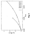
- the accompanying Figure 4 shows the variation of relative viscosity ( ⁇ rel ), that is, the ratio of the solution viscosity to that of 1:1 w/w Isopar/Halocarbon mixture, with weight fraction of PIB ( ⁇ PIB ) in the solution, this variation being of the expected form; the "best fit" curve is a cubic polynomial fit to the data, except that higher ⁇ PIB values not plotted in Figure 4 were included in the data used to determine the fit.
- the Figure shows the effect of weight fraction of polymer for the aforementioned PIB polymers 18145-5 and 18146-3.
- the solutions were Newtonian over the measured stress range of 0.01 to10 Pa (measured using a 75 mm diameter, 1° cone and plate geometry on a Physica UDS 200 controlled stress rheometer), which was sufficient to cover both the stresses imposed on the fluid by pigment particles during gravitational settling, and the stresses imposed by electrophoretic movement of the particles.
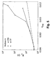
- Photo detector voltage was transformed to reflectivity by calibrating the voltage response to reflectivity measured with a spectrophotometer over the range 700 to 400 nm where the spectrophotometer was calibrated with a diffuse reflectivity standard.) The results are shown in Figure 5.
- reflectance persistence is defined as the time required for lightness L* (see, for example, Hunt, R.W.G. "Measuring Color,” 3rd edition, Fountain Press, guitarist-upon-Thames, England (1998).
- the broken line in Figure 5 is the viscosity-concentration curve for PIB (18145-5) of Figure 4 scaled to the reflectance persistence value at zero polymer concentration, and shows approximately the variation of reflectance persistence with polymer concentration which would be expected if changes in reflectance persistence were correlated with pigment settling, which in turn is correlated with changes in viscosity caused by addition of the polymer.
- the threshold concentration of polymer required for enhanced image stability of the dark state is considerably lower than that for the white state. Because for most display applications it is desirable to provide both dark and white state image stability, in this Example the threshold concentration for white state image stability determines how much polymer to add.
- the difference in threshold concentrations for white and dark states means that it is possible to produce electrophoretic media that have long time or enhanced image stability of the dark state (as provided by addition of the soluble polymer) and poor image stability of the white state, or image stability of the white state that is provided by another means.
- This Example illustrates that the addition of PIB to the suspending fluid in Medium B produces an increase in image stability greater than that attributable to the increase in relative viscosity caused by the PIB addition.
- Example 2 The PIB and Isopar V addition experiments of Example 1 were repeated with Medium B, except that 15 V switching pulses were used, this being the switching voltage for which Medium B was designed.
- the results are shown in the accompanying Figure 6, from which it will be seen that the results achieved with Medium B are qualitatively similar to those achieved with Medium A, as described in Example 1 above, except that the reflectance persistence enhancement provided with PIB only occurs at higher concentrations (greater than about 1.1 per cent by weight) with Medium B.
- This Example illustrates that the images produced using Media A and B with the addition of PIB degrade more slowly than do the images from modified Media A and B having a suspending fluid of essentially the same viscosity but lacking PIB.
- a Medium A display was prepared with 1.47 per cent by weight of PIB added to produce a relative viscosity ( ⁇ rel , the ratio of the viscosity of the modified medium to the unmodified medium) of 3.90.
- This Example illustrates that this invention allows the stabilization not only of the extreme (black and white) optical states of an electrophoretic display, but also intermediate gray states.
- a display was prepared using Medium A containing 1.53 weight per cent of PIB.
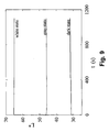
- the display was driven to its black and white states as described in Example 1 above, and also driven to an intermediate gray state by using a driving pulse shorter than that required to change the display from its black to its white state.
- the L* values of all three states were monitored over time, and the results are shown in Figure 9. From this Figure, it will be seen that the addition of the PIB was successful in stabilizing the intermediate gray state as well as the black and white states.
- This Example illustrates that the increase in image stability provided by the present invention is not significantly affected by temperature.
- This Example illustrates a method for determining the optimum molecular weight range of a polymer to be used in the electrophoretic medium of the present invention.
- Viscosity data such as that shown in Figure 4 can be used to determine the intrinsic viscosity for that polymer and solvent system.
- Intrinsic viscosity ([ ⁇ ]) is defined as the zero concentration limit of the ratio of specific viscosity ( ⁇ sp ) to polymer concentration (C), where specific viscosity is defined as ( ⁇ rel - 1); therefore, [ ⁇ ] can be determined directly from data such as that presented in Figure 4 (see for example Flory, P.J. "Principles of Polymer Chemistry", Cornell University Press: Ithaca, New York (1953)).
- Intrinsic viscosity [ ⁇ ] is a measure of the capacity of a polymer to enhance the viscosity of a solvent; it increases with molecular weight, and it is sensitive to solvent quality or the goodness of a solvent for a particular polymer chemistry.
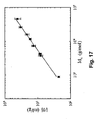
- the line shown in Figure 11 is a best linear fit to the data, and its slope is 0.61.
- a value of 0.5 indicates theta solvency conditions for the dissolved polymer, where theta solvency for a polymer/solvent pair is the condition at which an infinite molecular weight polymer will precipitate from the solvent. Larger values of a , for example 0.7 or greater, indicate good or possibly athermal solvency. Therefore, the slope of 0.61 observed in Figure 11 indicates that this aliphatic hydrocarbon/halogenated halocarbon solvent mixture is a moderately good solvent for PIB at 25°C.
- intrinsic viscosity measurements it is common to use intrinsic viscosity measurements as a method for determining the viscosity average molecular weight of a polymer. For example, if one has a series of different molecular weight polymers of the same chemistry where the molecular weights have been determined using another technique, for example light scattering or gel permeation chromatography, measurement of the intrinsic viscosity in a particular solvent allows preparation of a plot of intrinsic viscosity versus the known molecular weight such as that shown in Figure 11. Consequently, by measuring the intrinsic viscosity of a new sample of a polymer of that chemistry, a plot such as Figure 11 can be used to determine the viscosity average molecular weight of that sample.
- Part B Image stability of inks
- the lowest relative viscosity at which enhanced image stability was observed was denoted as the onset concentration of polymer; this onset concentration decreased monotonically with increasing polymer molecular weight. Since Medium B viscosity varies with polymer concentration and molecular weight and in most practical applications it is usually of interest to minimize medium viscosity in order to minimize the optical switching time of the display, it is useful to measure the threshold or onset concentration of polymer required for enhanced image stability as an onset relative viscosity. Figure 12 shows this onset relative viscosity as a function of polymer viscosity average molecular weight. At polymer concentrations below the curve in Figure 12, the Medium B media exhibit image stability that is consistent with the viscosity of the polymer solution.
- Figure 13 shows image stability (IS) as a function of the Medium B's relative viscosity where ⁇ rel was changed by addition of the various molecular weight polymers.
- IS image stability
- Medium B media exhibit significantly enhanced image stability with respect to the viscosity of the medium.
- image stability increases as polymer concentration is increased above the onset concentration, although as shown in Figure 6 for some polymer molecular weights the increase in image stability with polymer concentration is quite strong.
- the polyisobutylene with an M v of 4,600,000 g/mole the increase is weaker. Therefore, for a polymer with any given molecular weight, the polymer concentration can be "tuned" to achieve a degree of image stability. (The data presented in this Example do not imply that image stability increases without bound as polymer concentration is increased.
- Figure 12 shows that to minimize the onset relative viscosity required to achieve enhanced image stability, a polyisobutylene with M v of approximately 730,000 g/mole should be used (in the suspending fluid used in these tests).
- a practical electrophoretic medium may require image stabilities greater than that observed at the onset relative viscosity.
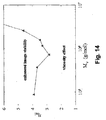
- Figure 14 shows that if, for example, an image stability of 400 seconds is desired, this can be achieved at the lowest relative viscosity by using the polyisobutylene with M v of 730,000 g/mole.
- This Example illustrates the use of polymers having low polydispersity indices in the electrophoretic medium of the present invention.
- the polyisobutylenes used in Example 6 above are inexpensive commercial materials with broad molecular weight distributions, as indicated by their polydispersity indices (PDI's) in excess of 1.5.
- the samples are organized according to the viscosity average molecular weight M v reported by the manufacturer. Table 1.
- Example 6 because the onset concentration for enhanced image stability was dependent on the molecular weight of the polymer, there was reason to suspect that narrow polymer molecular weight distributions would produce enhanced image stability at lower relative viscosities; by narrowing the molecular weight distribution, one is in effect removing low and high molecular weight material that does not contributing optimally to achieving the desired image stability. Accordingly, narrow molecular weight range polyisobutylene samples were purchased from Polymer Standards Service-USA Inc. (Silver Spring, MD) and American Polymer Standards Corporation (Mentor, OH). According to these manufacturers, these narrow distribution polyisobutylenes were prepared by fractionating commercially available high molecular weight polyisobutylene.
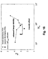
- Figure 16 also illustrates that the [ ⁇ ] -1 rule provides an excellent starting point for predicting the onset concentration of polymer necessary to produce image stability.
- the heavy line shows the [ ⁇ ] -1 rule predictions for image stability of the Table 2 polymers where the experimentally determined [ ⁇ ] values for these polymers in the Medium B suspending fluid are given in Table 2. Because [ ⁇ ] is sensitive to the molecular weight distribution and the solvent quality of the suspending fluid of an electrophoretic medium for a polymer, this result indicates that the [ ⁇ ] -1 rule provides a general method for predicting the concentration of a soluble polymer required to produce the onset of enhanced image stability in an electrophoretic medium.
- Example 6 The experiments described in this Example show that the relative viscosity increase of electrophoretic media caused by the addition of soluble polymer in accordance with the present invention can be minimized by reducing the breadth of the molecular weight distribution of the added polymer.
- the polymers used in Example 6 had polydispersity indices ranging from 1.6 to almost 3. By lowering the PDI to less than 1.3, the increase in relative viscosity due to addition of the polymer could be reduced by more than 30 percent for a polymer with a given M w .
- This rule does not exclude using broad, multi-modal distribution polymers to achieve image stability in the present invention; in fact some commercial polyisobutylenes have extremely broad molecular weight distributions, yet are still useful in this invention.
- the experiments described in this Example provide a rule for estimating the minimum concentration of polymer (and therefore minimum viscosity for a particular molecular weight) required to produce enhanced image stability.
- the rule is that the onset concentration of a given molecular weight polymer required to produce enhanced image stability will be found in the vicinity of [ ⁇ ] -1 . This rule is useful because it can be applied to guide formulation in other polymer/suspending systems which may be of interest in electrophoretic media.
- This Example illustrates the solvent qualities needed in a suspending fluid for a polymer used in the electrophoretic medium of the present invention.
- Medium C displays were prepared using the polyisobutylene with M v 730,000 g/mole, where the concentration of polymer was determined using the constant [ ⁇ ]C PIB rule derived in the previous Example.
- the displays produced had comparable image stability to that expected based on the behavior of Medium B displays prepared in Example 6 above.
- the display behaves as if no polyisobutylene is present, and indeed this is consistent with an observation that the concentrated polyisobutylene stock solution used to prepare the displays did not mix into such a suspending fluid.
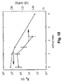
- Figure 18 also shows that the intrinsic viscosity of M v 730,000 g/mole polyisobutylene as a function of solvent ratio; the decrease in [ ⁇ ] with increasing halocarbon content indicates that the solvent quality gets poorer.
- a solvent quality criterion for choosing a polymer and suspending fluid for producing enhanced image stability in an electrophoretic display can be suggested: the polymer/suspending fluid combination must be such that the fluid is at least a theta solvent for the polymer at room temperature.
- the suspending fluid should be at least a moderately good to good solvent for the polymer. As described earlier, this can be reflected in the scaling exponent a for intrinsic viscosity with molecular weight, where the above criterion suggests a slope of at least 0.5, optimally a slope of 0.55 ⁇ a ⁇ 0.8.
- the data provided in this Example define a range of acceptable solvent qualities for polymer/suspending fluid combinations for producing enhanced image stability in electrophoretic displays.
- the data show that polyisobutylene can be used to produce enhanced image stability over a range of suspending fluids, and that good enhanced image stability is observed when the fluid is verified to be at least a moderately good solvent for the polymer.
- the solvent quality of the fluid for polyisobutylene is made poorer by changing its composition, the image stability is degraded.
- polymer/suspending fluid combinations should be chosen such that the scaling exponent a for intrinsic viscosity with molecular weight at room temperature falls within the range 0.55 ⁇ a ⁇ 0.8, with higher values of a being better.
- Image stability in Medium C displays which differ substantially in pigment concentration from Medium A and B displays, also demonstrates that the effectiveness of polymer in inducing image stability can be maintained over a broad concentration of pigment.
- This Example illustrates the preparation of electrophoretic media having image stabilities of several hours to days.
- Medium C displays were prepared using 53.5 g of a 13 weight percent solution of 730,000 viscosity average molecular weight polyisobutylene in Isopar solvent in each 1064 g. of Medium C internal phase prepared as described above. The displays were then subjected to five different types of optical state transitions, namely black-to-white (b ⁇ w), white-to-black (w ⁇ b), black-to-gray (b ⁇ g), white-to-gray (w ⁇ g), and gray-to-gray (g ⁇ g) where black and white denote the extreme optical states of the display.
- the black-to-white (b ⁇ w) and white-to-black (w ⁇ b) transitions were effected by exposing the medium to 15 V for 0.3 seconds, with correspondingly shorter drive pulses for the other transitions; after application of this single drive pulse, the display was left unpowered for the remainder of each experiment.
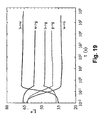
- the L* of each display was measured in the manner previously described during and after the application of the drive pulse, and the results are shown in Figure 19. Because the time scale of the measurements covers eight orders of magnitude, the onset of each transition appears digitized.
- Figure 19 shows that white and black states of these displays exhibit image stabilities of the order of 10 6 seconds.
- Careful study of, for example, the b ⁇ w transition in Figure 19, reveals that after the drive pulse was completed there was a slow decay in white state lightness; however, the total decay over the time scale covered in Figure 19 was still only approximately 1-2 L*, so the image stability is greater than 10 6 seconds.
- the most significant change in lightness occurs at relatively short times with the rate of change decreasing to extremely low values as the measurement time exceeds 10 3 seconds. Indeed, it was observed visually that these lightness states persist for months, i.e., over periods in excess of 10 7 seconds, but this very long time image stability was not followed quantitatively.
- the image stability behavior was reproducible over months of switching and long time residence of the display in a lightness state does not affect the ability to achieve the lightness in subsequent transitions, i.e., no permanent image retention or image burn-in was observed.
- Figure 19 also shows that Medium C gray states were image stable, exhibiting lightness decay rates similar to those observed for the black and white states.
- the gray state image stability thus demonstrated enables development of a general image flow waveform for switching pixels, i . e ., gray-to-gray addressing in an electrophoretic display.
- This Example illustrates general image stability in a Medium C type electrophoretic medium, and shows the stability of black and white states, as well as intermediate gray states. This Example also shows that the stability of a given display state is the same independent of the path by which this state is reached, and that extremely long term image stability, at least of the order of 10 6 seconds, can be achieved in a low voltage rapidly addressed electrophoretic medium.
- Example 9 illustrates that the image stabilities of the various states shown in Example 9 are substantially independent of temperature.
- Portable information appliances such as personal digital assistants (PDA's), and other consumer devices are exposed to a broad range of temperatures during normal use, and thus the displays used in appliances and devices need to operate over a range of (typically) 0 to 50°C.
- the experiments described in Example 9 were repeated over this temperature range, and it was confirmed that the image stability was not substantially affected by temperatures within this range.
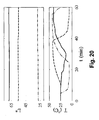
- Example 9 Experiments were also conducted to determine whether any changes occurred when a display was driven to a specific optical state at one temperature and the temperature of the display was thereafter changed. More specifically, the displays used in Example 9 were driven to their black, gray and white states at 25°C in the manner described in that Example, and thereafter the displays were left unpowered while the temperature was varied over the range of 0 to 50°C. The results are shown in Figure 20; the lower part of this Figure shows the variation of temperature of the black, gray and white displays with time, while the upper part of this Figure shows the variation of L* with time. It will be seen that changes in temperature within this range had substantially no effect on the optical states of the displays.
- This Example shows that polymers such as polyisobutylene can be used to achieve image stability over the typical operating temperature range of a display.
- a display with this type of image stability can be expected to maintain an image even if the external environmental temperature alters the display temperature significantly.
- This Example illustrates that addition of a polymer to an electrophoretic medium in accordance with the present invention provides a non-linear response to a low voltage impulse applied to the medium.
- a hybrid Medium B/Medium C display was prepared using a suspending fluid, surfactant, binder, lamination adhesive and fabrication process substantially the same as the Medium B description above, but with a pigment loading and capsule size substantially the same as the Medium C description above.
- This hybrid medium contained polyisobutylene (18146-3) at a concentration such that ⁇ rel was 3.3.
- This display switched between its black and white states using a drive pulse of 15 V for 500 milliseconds, and had an image stability in excess of 10 6 seconds.
- the white state had an L* value of 68 and the black state an L* value of 22, as indicated by the broken lines in Figure 21.
- This weak threshold behavior is advantageous because it makes the display insensitive to any DC offset parasitic voltages (typically up to several hundred mV of both positive or negative bias) present in the backplane of an active matrix display (these parasitic voltage are continuous whenever the transistors of the backplane are powered).
- DC offset parasitic voltages typically up to several hundred mV of both positive or negative bias
- the impulse non-linearity of the electrophoretic medium can be adjusted by altering the concentration of the polymer used to produce the enhanced image stability.
- the severity of the non-linearity increases with increasing polymer concentration for concentrations above the onset concentration for any given molecular weight polymer.
- electrophoretic displays exhibit a greater apparent threshold voltage. High thresholds may be a desirable attribute to enable use of electrophoretic media with passive matrix addressing schemes.
- This Example shows that adding a polymer to the suspending fluid to provide enhanced image stability in accordance with the present invention also changes the optical response of the medium, making this response non-linear to impulse in a manner analogous to the strong shear thinning behavior in rheology.
- This non-linear impulse response causes the medium to appear to exhibit a voltage threshold behavior.
- the nature or degree of the non-linearity can be adjusted by adjusting the polymer concentration, the severity of the non-linear behavior increasing with increasing polymer concentration and becoming significant at concentrations greater than the onset concentration. This phenomenon may be useful for developing inexpensive passively addressed displays.
- the electrophoretic media of the present invention may employ the same components and manufacturing techniques as in the aforementioned patents and applications, to which the reader is referred for further information.
- the present invention provides a substantial increase in the stability of images produced by electrophoretic displays, thus increasing the utility of such displays, especially in applications such as portable devices in which reducing the energy consumption of the display is of great importance. Furthermore, preferred variants of the present invention allow this increase in image stability to be achieved using inexpensive, non-toxic materials which are readily available commercially.
Landscapes
- Physics & Mathematics (AREA)
- Nonlinear Science (AREA)
- General Physics & Mathematics (AREA)
- Engineering & Computer Science (AREA)
- Life Sciences & Earth Sciences (AREA)
- Health & Medical Sciences (AREA)
- Chemical & Material Sciences (AREA)
- Chemical Kinetics & Catalysis (AREA)
- Electrochemistry (AREA)
- Molecular Biology (AREA)
- Optics & Photonics (AREA)
- Theoretical Computer Science (AREA)
- Computer Hardware Design (AREA)
- Electrochromic Elements, Electrophoresis, Or Variable Reflection Or Absorption Elements (AREA)
- Photoreceptors In Electrophotography (AREA)
Applications Claiming Priority (3)
| Application Number | Priority Date | Filing Date | Title |
|---|---|---|---|
| US28095101P | 2001-04-02 | 2001-04-02 | |
| PCT/US2002/010267 WO2002079869A1 (fr) | 2001-04-02 | 2002-04-02 | Milieu electrophoretique a stabilite d'image amelioree |
| EP02757934A EP1390810B1 (fr) | 2001-04-02 | 2002-04-02 | Milieu electrophoretique a stabilite d'image amelioree |
Related Parent Applications (1)
| Application Number | Title | Priority Date | Filing Date |
|---|---|---|---|
| EP02757934A Division EP1390810B1 (fr) | 2001-04-02 | 2002-04-02 | Milieu electrophoretique a stabilite d'image amelioree |
Publications (3)
| Publication Number | Publication Date |
|---|---|
| EP1666964A2 true EP1666964A2 (fr) | 2006-06-07 |
| EP1666964A3 EP1666964A3 (fr) | 2007-03-14 |
| EP1666964B1 EP1666964B1 (fr) | 2018-12-19 |
Family
ID=23075315
Family Applications (2)
| Application Number | Title | Priority Date | Filing Date |
|---|---|---|---|
| EP06002515.2A Expired - Lifetime EP1666964B1 (fr) | 2001-04-02 | 2002-04-02 | Support électrophorétique avec stabilité d'image améliorée |
| EP02757934A Expired - Lifetime EP1390810B1 (fr) | 2001-04-02 | 2002-04-02 | Milieu electrophoretique a stabilite d'image amelioree |
Family Applications After (1)
| Application Number | Title | Priority Date | Filing Date |
|---|---|---|---|
| EP02757934A Expired - Lifetime EP1390810B1 (fr) | 2001-04-02 | 2002-04-02 | Milieu electrophoretique a stabilite d'image amelioree |
Country Status (8)
| Country | Link |
|---|---|
| US (1) | US7170670B2 (fr) |
| EP (2) | EP1666964B1 (fr) |
| JP (2) | JP4568477B2 (fr) |
| KR (1) | KR100824249B1 (fr) |
| CN (1) | CN1282027C (fr) |
| AT (1) | ATE324615T1 (fr) |
| DE (1) | DE60210949T2 (fr) |
| WO (1) | WO2002079869A1 (fr) |
Families Citing this family (489)
| Publication number | Priority date | Publication date | Assignee | Title |
|---|---|---|---|---|
| US7327511B2 (en) | 2004-03-23 | 2008-02-05 | E Ink Corporation | Light modulators |
| US7583251B2 (en) | 1995-07-20 | 2009-09-01 | E Ink Corporation | Dielectrophoretic displays |
| US8139050B2 (en) | 1995-07-20 | 2012-03-20 | E Ink Corporation | Addressing schemes for electronic displays |
| US7411719B2 (en) | 1995-07-20 | 2008-08-12 | E Ink Corporation | Electrophoretic medium and process for the production thereof |
| US7259744B2 (en) * | 1995-07-20 | 2007-08-21 | E Ink Corporation | Dielectrophoretic displays |
| US7193625B2 (en) | 1999-04-30 | 2007-03-20 | E Ink Corporation | Methods for driving electro-optic displays, and apparatus for use therein |
| US7848006B2 (en) * | 1995-07-20 | 2010-12-07 | E Ink Corporation | Electrophoretic displays with controlled amounts of pigment |
| US7999787B2 (en) | 1995-07-20 | 2011-08-16 | E Ink Corporation | Methods for driving electrophoretic displays using dielectrophoretic forces |
| US7167155B1 (en) | 1995-07-20 | 2007-01-23 | E Ink Corporation | Color electrophoretic displays |
| US7002728B2 (en) | 1997-08-28 | 2006-02-21 | E Ink Corporation | Electrophoretic particles, and processes for the production thereof |
| US7247379B2 (en) | 1997-08-28 | 2007-07-24 | E Ink Corporation | Electrophoretic particles, and processes for the production thereof |
| US8040594B2 (en) | 1997-08-28 | 2011-10-18 | E Ink Corporation | Multi-color electrophoretic displays |
| US7075502B1 (en) | 1998-04-10 | 2006-07-11 | E Ink Corporation | Full color reflective display with multichromatic sub-pixels |
| EP1093600B1 (fr) * | 1998-07-08 | 2004-09-15 | E Ink Corporation | Procedes permettant d'ameliorer la couleur des dispositifs electrophoretiques microencapsules |
| US7012600B2 (en) | 1999-04-30 | 2006-03-14 | E Ink Corporation | Methods for driving bistable electro-optic displays, and apparatus for use therein |
| US7119772B2 (en) | 1999-04-30 | 2006-10-10 | E Ink Corporation | Methods for driving bistable electro-optic displays, and apparatus for use therein |
| US8115729B2 (en) | 1999-05-03 | 2012-02-14 | E Ink Corporation | Electrophoretic display element with filler particles |
| US8009348B2 (en) | 1999-05-03 | 2011-08-30 | E Ink Corporation | Machine-readable displays |
| US7119759B2 (en) | 1999-05-03 | 2006-10-10 | E Ink Corporation | Machine-readable displays |
| US7893435B2 (en) | 2000-04-18 | 2011-02-22 | E Ink Corporation | Flexible electronic circuits and displays including a backplane comprising a patterned metal foil having a plurality of apertures extending therethrough |
| US6858164B2 (en) * | 2001-01-26 | 2005-02-22 | Ricoh Company Limited | Silicone-oil soluble polymer, image display medium using the silicone-oil soluble polymer and image display device using the image display medium |
| AU2002250304A1 (en) * | 2001-03-13 | 2002-09-24 | E Ink Corporation | Apparatus for displaying drawings |
| US20050156340A1 (en) * | 2004-01-20 | 2005-07-21 | E Ink Corporation | Preparation of capsules |
| US7679814B2 (en) * | 2001-04-02 | 2010-03-16 | E Ink Corporation | Materials for use in electrophoretic displays |
| US8390918B2 (en) * | 2001-04-02 | 2013-03-05 | E Ink Corporation | Electrophoretic displays with controlled amounts of pigment |
| US7230750B2 (en) | 2001-05-15 | 2007-06-12 | E Ink Corporation | Electrophoretic media and processes for the production thereof |
| US20090009852A1 (en) * | 2001-05-15 | 2009-01-08 | E Ink Corporation | Electrophoretic particles and processes for the production thereof |
| WO2002093245A1 (fr) * | 2001-05-15 | 2002-11-21 | E Ink Corporation | Ecrans electrophoretiques contenant des particules magnetiques |
| JP4188091B2 (ja) | 2001-05-15 | 2008-11-26 | イー インク コーポレイション | 電気泳動粒子 |
| US8582196B2 (en) | 2001-05-15 | 2013-11-12 | E Ink Corporation | Electrophoretic particles and processes for the production thereof |
| WO2003007067A1 (fr) * | 2001-07-09 | 2003-01-23 | E Ink Corporation | Affichage electro-optique et composition adhesive |
| AU2002354672A1 (en) * | 2001-07-09 | 2003-01-29 | E Ink Corporation | Electro-optical display having a lamination adhesive layer |
| US7110163B2 (en) | 2001-07-09 | 2006-09-19 | E Ink Corporation | Electro-optic display and lamination adhesive for use therein |
| US7535624B2 (en) * | 2001-07-09 | 2009-05-19 | E Ink Corporation | Electro-optic display and materials for use therein |
| US6982178B2 (en) | 2002-06-10 | 2006-01-03 | E Ink Corporation | Components and methods for use in electro-optic displays |
| US6819471B2 (en) * | 2001-08-16 | 2004-11-16 | E Ink Corporation | Light modulation by frustration of total internal reflection |
| US6825970B2 (en) * | 2001-09-14 | 2004-11-30 | E Ink Corporation | Methods for addressing electro-optic materials |
| US8125501B2 (en) | 2001-11-20 | 2012-02-28 | E Ink Corporation | Voltage modulated driver circuits for electro-optic displays |
| US8593396B2 (en) | 2001-11-20 | 2013-11-26 | E Ink Corporation | Methods and apparatus for driving electro-optic displays |
| US9530363B2 (en) | 2001-11-20 | 2016-12-27 | E Ink Corporation | Methods and apparatus for driving electro-optic displays |
| CN102789764B (zh) | 2001-11-20 | 2015-05-27 | 伊英克公司 | 驱动双稳态电光显示器的方法 |
| US7528822B2 (en) | 2001-11-20 | 2009-05-05 | E Ink Corporation | Methods for driving electro-optic displays |
| US8558783B2 (en) | 2001-11-20 | 2013-10-15 | E Ink Corporation | Electro-optic displays with reduced remnant voltage |
| US9412314B2 (en) | 2001-11-20 | 2016-08-09 | E Ink Corporation | Methods for driving electro-optic displays |
| US7952557B2 (en) | 2001-11-20 | 2011-05-31 | E Ink Corporation | Methods and apparatus for driving electro-optic displays |
| US6950220B2 (en) * | 2002-03-18 | 2005-09-27 | E Ink Corporation | Electro-optic displays, and methods for driving same |
| US7223672B2 (en) | 2002-04-24 | 2007-05-29 | E Ink Corporation | Processes for forming backplanes for electro-optic displays |
| US7190008B2 (en) | 2002-04-24 | 2007-03-13 | E Ink Corporation | Electro-optic displays, and components for use therein |
| WO2003092077A2 (fr) | 2002-04-24 | 2003-11-06 | E Ink Corporation | Fonds de panier pour applications d'affichage |
| US7510638B2 (en) * | 2002-05-10 | 2009-03-31 | The Trustees Of Columbia University In The City Of New York | Method of electric field assisted deposition of films of nanoparticles |
| US6958848B2 (en) * | 2002-05-23 | 2005-10-25 | E Ink Corporation | Capsules, materials for use therein and electrophoretic media and displays containing such capsules |
| US7843621B2 (en) * | 2002-06-10 | 2010-11-30 | E Ink Corporation | Components and testing methods for use in the production of electro-optic displays |
| US7649674B2 (en) | 2002-06-10 | 2010-01-19 | E Ink Corporation | Electro-optic display with edge seal |
| US7583427B2 (en) * | 2002-06-10 | 2009-09-01 | E Ink Corporation | Components and methods for use in electro-optic displays |
| US9470950B2 (en) | 2002-06-10 | 2016-10-18 | E Ink Corporation | Electro-optic displays, and processes for the production thereof |
| US8363299B2 (en) * | 2002-06-10 | 2013-01-29 | E Ink Corporation | Electro-optic displays, and processes for the production thereof |
| US8049947B2 (en) * | 2002-06-10 | 2011-11-01 | E Ink Corporation | Components and methods for use in electro-optic displays |
| US7110164B2 (en) | 2002-06-10 | 2006-09-19 | E Ink Corporation | Electro-optic displays, and processes for the production thereof |
| US20110199671A1 (en) * | 2002-06-13 | 2011-08-18 | E Ink Corporation | Methods for driving electrophoretic displays using dielectrophoretic forces |
| US20080024482A1 (en) | 2002-06-13 | 2008-01-31 | E Ink Corporation | Methods for driving electro-optic displays |
| JP4651383B2 (ja) | 2002-06-13 | 2011-03-16 | イー インク コーポレイション | 電気光学表示装置の駆動の方法 |
| US8780038B2 (en) * | 2002-06-18 | 2014-07-15 | Bsh Bosch Und Siemens Hausgerate Gmbh | Refrigerator comprising a function display unit |
| US7312916B2 (en) * | 2002-08-07 | 2007-12-25 | E Ink Corporation | Electrophoretic media containing specularly reflective particles |
| US7839564B2 (en) | 2002-09-03 | 2010-11-23 | E Ink Corporation | Components and methods for use in electro-optic displays |
| CN101109885B (zh) | 2002-09-03 | 2012-06-13 | 伊英克公司 | 电光显示器 |
| AU2003260137A1 (en) * | 2002-09-03 | 2004-03-29 | E Ink Corporation | Electrophoretic medium with gaseous suspending fluid |
| KR20050049526A (ko) * | 2002-10-10 | 2005-05-25 | 코닌클리케 필립스 일렉트로닉스 엔.브이. | 전기영동 디스플레이 패널 |
| US20130063333A1 (en) | 2002-10-16 | 2013-03-14 | E Ink Corporation | Electrophoretic displays |
| ATE320022T1 (de) * | 2002-10-18 | 2006-03-15 | Koninkl Philips Electronics Nv | Elektrophoretische anzeigevorrichtung |
| JP3796499B2 (ja) * | 2002-11-06 | 2006-07-12 | キヤノン株式会社 | カラー表示素子、カラー表示素子の駆動方法及びカラー表示装置 |
| US7176878B2 (en) | 2002-12-11 | 2007-02-13 | Nvidia Corporation | Backlight dimming and LCD amplitude boost |
| JP2006510066A (ja) | 2002-12-16 | 2006-03-23 | イー−インク コーポレイション | 電気光学表示装置用バックプレーン |
| US6922276B2 (en) | 2002-12-23 | 2005-07-26 | E Ink Corporation | Flexible electro-optic displays |
| WO2004066255A1 (fr) * | 2003-01-24 | 2004-08-05 | Koninklijke Philips Electronics N.V. | Afficheur electrophoretique |
| US6987603B2 (en) | 2003-01-31 | 2006-01-17 | E Ink Corporation | Construction of electrophoretic displays |
| US7015893B2 (en) * | 2003-01-31 | 2006-03-21 | Motorola, Inc. | Photoluminescent electrophoretic display |
| US20060227097A1 (en) * | 2003-02-27 | 2006-10-12 | Koninklijke Philips Electronics N.V. | Electrophoretic active matrix display device |
| US7910175B2 (en) * | 2003-03-25 | 2011-03-22 | E Ink Corporation | Processes for the production of electrophoretic displays |
| US7339715B2 (en) | 2003-03-25 | 2008-03-04 | E Ink Corporation | Processes for the production of electrophoretic displays |
| EP1616217B1 (fr) | 2003-03-27 | 2010-10-20 | E Ink Corporation | Ensembles electro-optiques |
| US9672766B2 (en) | 2003-03-31 | 2017-06-06 | E Ink Corporation | Methods for driving electro-optic displays |
| WO2004090857A1 (fr) * | 2003-03-31 | 2004-10-21 | E Ink Corporation | Procedes de commande d'afficheurs electro-optiques bistables |
| US10726798B2 (en) | 2003-03-31 | 2020-07-28 | E Ink Corporation | Methods for operating electro-optic displays |
| JP4776532B2 (ja) * | 2003-05-02 | 2011-09-21 | イー インク コーポレイション | 電気泳動ディスプレイ |
| CN101387809A (zh) * | 2003-05-02 | 2009-03-18 | 伊英克公司 | 电泳介质和包含电泳介质的电泳显示器 |
| JP2007500875A (ja) * | 2003-05-16 | 2007-01-18 | コーニンクレッカ フィリップス エレクトロニクス エヌ ヴィ | 電気泳動式表示パネル |
| JP2007501439A (ja) * | 2003-05-22 | 2007-01-25 | コーニンクレッカ フィリップス エレクトロニクス エヌ ヴィ | 電気泳動ディスプレイ及び駆動方法 |
| US8174490B2 (en) * | 2003-06-30 | 2012-05-08 | E Ink Corporation | Methods for driving electrophoretic displays |
| EP1639574B1 (fr) | 2003-06-30 | 2015-04-22 | E Ink Corporation | Procedes d'attaque d'afficheurs electro-optiques |
| US20050122563A1 (en) | 2003-07-24 | 2005-06-09 | E Ink Corporation | Electro-optic displays |
| EP1656658A4 (fr) | 2003-08-19 | 2009-12-30 | E Ink Corp | Procedes de commande pour affichages electro-optiques |
| JP2007504378A (ja) * | 2003-09-04 | 2007-03-01 | コニンクリユケ フィリップス エレクトロニクス エヌ.ブイ. | ダイナミック道路標識ユニット |
| WO2005024135A1 (fr) * | 2003-09-04 | 2005-03-17 | Koninklijke Philips Electronics N.V. | Systeme de signalisation horizontale sur des routes |
| WO2005029458A1 (fr) | 2003-09-19 | 2005-03-31 | E Ink Corporation | Procede de reduction d'effets de bord dans des afficheurs |
| JP4848280B2 (ja) * | 2003-10-08 | 2011-12-28 | イー インク コーポレイション | 電気泳動媒質 |
| US7420549B2 (en) | 2003-10-08 | 2008-09-02 | E Ink Corporation | Electro-wetting displays |
| US8319759B2 (en) | 2003-10-08 | 2012-11-27 | E Ink Corporation | Electrowetting displays |
| US7672040B2 (en) * | 2003-11-05 | 2010-03-02 | E Ink Corporation | Electro-optic displays, and materials for use therein |
| US8177942B2 (en) * | 2003-11-05 | 2012-05-15 | E Ink Corporation | Electro-optic displays, and materials for use therein |
| US7173752B2 (en) | 2003-11-05 | 2007-02-06 | E Ink Corporation | Electro-optic displays, and materials for use therein |
| US7551346B2 (en) * | 2003-11-05 | 2009-06-23 | E Ink Corporation | Electro-optic displays, and materials for use therein |
| US20110164301A1 (en) | 2003-11-05 | 2011-07-07 | E Ink Corporation | Electro-optic displays, and materials for use therein |
| US7548291B2 (en) | 2003-11-12 | 2009-06-16 | Lg Display Lcd Co., Ltd. | Reflective type liquid crystal display device and fabrication method thereof |
| US8928562B2 (en) | 2003-11-25 | 2015-01-06 | E Ink Corporation | Electro-optic displays, and methods for driving same |
| JP4790622B2 (ja) * | 2003-11-26 | 2011-10-12 | イー インク コーポレイション | 低残留電圧の電気光学ディスプレイ |
| US7206119B2 (en) | 2003-12-31 | 2007-04-17 | E Ink Corporation | Electro-optic displays, and method for driving same |
| US7075703B2 (en) | 2004-01-16 | 2006-07-11 | E Ink Corporation | Process for sealing electro-optic displays |
| US7079304B2 (en) | 2004-01-23 | 2006-07-18 | The Lubrizol Corporation | Structured fluid compositions for electrophoretically frustrated total internal reflection displays |
| JP4691883B2 (ja) * | 2004-01-30 | 2011-06-01 | 富士ゼロックス株式会社 | 表示デバイス用粒子の製造方法 |
| KR20060135733A (ko) * | 2004-02-06 | 2006-12-29 | 코닌클리케 필립스 일렉트로닉스 엔.브이. | 전기영동 디스플레이 패널 |
| US7388572B2 (en) * | 2004-02-27 | 2008-06-17 | E Ink Corporation | Backplanes for electro-optic displays |
| US7492339B2 (en) * | 2004-03-26 | 2009-02-17 | E Ink Corporation | Methods for driving bistable electro-optic displays |
| US7118838B2 (en) * | 2004-03-26 | 2006-10-10 | Brother International Corporation | Method, apparatus and media for displaying information |
| US8289250B2 (en) * | 2004-03-31 | 2012-10-16 | E Ink Corporation | Methods for driving electro-optic displays |
| JP4513414B2 (ja) * | 2004-05-11 | 2010-07-28 | 富士ゼロックス株式会社 | 画像表示装置 |
| JP4708736B2 (ja) * | 2004-05-31 | 2011-06-22 | キヤノン株式会社 | 電気泳動粒子及びその製造方法 |
| US11250794B2 (en) | 2004-07-27 | 2022-02-15 | E Ink Corporation | Methods for driving electrophoretic displays using dielectrophoretic forces |
| US20080136774A1 (en) | 2004-07-27 | 2008-06-12 | E Ink Corporation | Methods for driving electrophoretic displays using dielectrophoretic forces |
| WO2006015044A1 (fr) | 2004-07-27 | 2006-02-09 | E Ink Corporation | Affichages electro-optiques |
| US7453445B2 (en) | 2004-08-13 | 2008-11-18 | E Ink Corproation | Methods for driving electro-optic displays |
| JP2008521065A (ja) | 2005-01-26 | 2008-06-19 | イー インク コーポレイション | ガス状流体を用いる電気泳動ディスプレイ |
| WO2007002452A2 (fr) | 2005-06-23 | 2007-01-04 | E Ink Corporation | Joints d'arête et procédés d’affichage électro-optiques |
| KR101256713B1 (ko) | 2005-10-18 | 2013-04-19 | 이 잉크 코포레이션 | 전기-광학 디스플레이용 컴포넌트 |
| US20080043318A1 (en) | 2005-10-18 | 2008-02-21 | E Ink Corporation | Color electro-optic displays, and processes for the production thereof |
| US20070091417A1 (en) * | 2005-10-25 | 2007-04-26 | E Ink Corporation | Electrophoretic media and displays with improved binder |
| TWI380114B (en) * | 2005-12-15 | 2012-12-21 | Nlt Technologies Ltd | Electrophoretic display device and driving method for same |
| KR100664462B1 (ko) * | 2005-12-21 | 2007-01-04 | 호서대학교 산학협력단 | 전도성고분자 마이크로캡슐을 이용한 복합코아세르베이션방법으로 제조된 전기영동 디스플레이 |
| US7830548B2 (en) * | 2006-01-09 | 2010-11-09 | Adobe Systems Incorporated | Method and apparatus for generating color toning curves |
| US8390301B2 (en) * | 2006-03-08 | 2013-03-05 | E Ink Corporation | Electro-optic displays, and materials and methods for production thereof |
| US7843624B2 (en) * | 2006-03-08 | 2010-11-30 | E Ink Corporation | Electro-optic displays, and materials and methods for production thereof |
| US7733554B2 (en) * | 2006-03-08 | 2010-06-08 | E Ink Corporation | Electro-optic displays, and materials and methods for production thereof |
| US8610988B2 (en) | 2006-03-09 | 2013-12-17 | E Ink Corporation | Electro-optic display with edge seal |
| US7952790B2 (en) * | 2006-03-22 | 2011-05-31 | E Ink Corporation | Electro-optic media produced using ink jet printing |
| US7903319B2 (en) * | 2006-07-11 | 2011-03-08 | E Ink Corporation | Electrophoretic medium and display with improved image stability |
| US8018640B2 (en) | 2006-07-13 | 2011-09-13 | E Ink Corporation | Particles for use in electrophoretic displays |
| US20080024429A1 (en) * | 2006-07-25 | 2008-01-31 | E Ink Corporation | Electrophoretic displays using gaseous fluids |
| US7492497B2 (en) * | 2006-08-02 | 2009-02-17 | E Ink Corporation | Multi-layer light modulator |
| JP5298016B2 (ja) * | 2006-08-17 | 2013-09-25 | アドレア エルエルシー | 電気泳動式表示装置 |
| US7986450B2 (en) | 2006-09-22 | 2011-07-26 | E Ink Corporation | Electro-optic display and materials for use therein |
| US7477444B2 (en) | 2006-09-22 | 2009-01-13 | E Ink Corporation & Air Products And Chemical, Inc. | Electro-optic display and materials for use therein |
| JP5135771B2 (ja) * | 2006-11-17 | 2013-02-06 | 富士ゼロックス株式会社 | 表示装置、書込み装置、及び表示プログラム |
| US7649666B2 (en) * | 2006-12-07 | 2010-01-19 | E Ink Corporation | Components and methods for use in electro-optic displays |
| WO2008091850A2 (fr) * | 2007-01-22 | 2008-07-31 | E Ink Corporation | Feuille à plusieurs couches destinée à être utilisée dans des afficheurs électro-optiques |
| US7688497B2 (en) * | 2007-01-22 | 2010-03-30 | E Ink Corporation | Multi-layer sheet for use in electro-optic displays |
| US7826129B2 (en) | 2007-03-06 | 2010-11-02 | E Ink Corporation | Materials for use in electrophoretic displays |
| CN101681211A (zh) * | 2007-05-21 | 2010-03-24 | 伊英克公司 | 用于驱动视频电光显示器的方法 |
| US9199441B2 (en) * | 2007-06-28 | 2015-12-01 | E Ink Corporation | Processes for the production of electro-optic displays, and color filters for use therein |
| WO2009006248A1 (fr) | 2007-06-29 | 2009-01-08 | E Ink Corporation | Dispositifs d'affichage électro-optiques, et matériaux et procédé pour la production de ceux-ci |
| US8902153B2 (en) | 2007-08-03 | 2014-12-02 | E Ink Corporation | Electro-optic displays, and processes for their production |
| US9186640B2 (en) * | 2007-08-28 | 2015-11-17 | Pepsico, Inc. | Delivery and controlled release of encapsulated lipophilic nutrients |
| US20090122389A1 (en) | 2007-11-14 | 2009-05-14 | E Ink Corporation | Electro-optic assemblies, and adhesives and binders for use therein |
| US8054526B2 (en) * | 2008-03-21 | 2011-11-08 | E Ink Corporation | Electro-optic displays, and color filters for use therein |
| US8373649B2 (en) * | 2008-04-11 | 2013-02-12 | Seiko Epson Corporation | Time-overlapping partial-panel updating of a bistable electro-optic display |
| US8314784B2 (en) | 2008-04-11 | 2012-11-20 | E Ink Corporation | Methods for driving electro-optic displays |
| JP5353092B2 (ja) | 2008-07-03 | 2013-11-27 | 株式会社リコー | 電気泳動分散液、並びにこれを用いた画像表示媒体、及び画像表示装置 |
| US8234507B2 (en) | 2009-01-13 | 2012-07-31 | Metrologic Instruments, Inc. | Electronic-ink display device employing a power switching mechanism automatically responsive to predefined states of device configuration |
| US8457013B2 (en) | 2009-01-13 | 2013-06-04 | Metrologic Instruments, Inc. | Wireless dual-function network device dynamically switching and reconfiguring from a wireless network router state of operation into a wireless network coordinator state of operation in a wireless communication network |
| JP5388028B2 (ja) * | 2009-01-13 | 2014-01-15 | 株式会社リコー | 画像表示媒体及び画像表示装置 |
| US20100177076A1 (en) * | 2009-01-13 | 2010-07-15 | Metrologic Instruments, Inc. | Edge-lit electronic-ink display device for use in indoor and outdoor environments |
| US20100177080A1 (en) * | 2009-01-13 | 2010-07-15 | Metrologic Instruments, Inc. | Electronic-ink signage device employing thermal packaging for outdoor weather applications |
| US20100177750A1 (en) * | 2009-01-13 | 2010-07-15 | Metrologic Instruments, Inc. | Wireless Diplay sensor communication network |
| JP2012517487A (ja) | 2009-02-09 | 2012-08-02 | メルク パテント ゲゼルシャフト ミット ベシュレンクテル ハフツング | 電気泳動ディスプレイのための粒子 |
| TWI484273B (zh) * | 2009-02-09 | 2015-05-11 | E Ink Corp | 電泳粒子 |
| WO2010089057A2 (fr) | 2009-02-09 | 2010-08-12 | Merck Patent Gmbh | Particules pour affichages électrophorétiques |
| US8462423B2 (en) | 2009-02-09 | 2013-06-11 | Merck Patent Gmbh | Coloured particles for electrophoretic displays |
| US8743451B2 (en) | 2009-02-09 | 2014-06-03 | Merck Patent Gmbh | Coloured particles for electrophoretic displays |
| US8098418B2 (en) | 2009-03-03 | 2012-01-17 | E. Ink Corporation | Electro-optic displays, and color filters for use therein |
| WO2011046563A1 (fr) * | 2009-10-16 | 2011-04-21 | Hewlett Packard Development Company, L.P. | Encres électroniques |
| US8754859B2 (en) | 2009-10-28 | 2014-06-17 | E Ink Corporation | Electro-optic displays with touch sensors and/or tactile feedback |
| US8654436B1 (en) | 2009-10-30 | 2014-02-18 | E Ink Corporation | Particles for use in electrophoretic displays |
| WO2011097228A2 (fr) | 2010-02-02 | 2011-08-11 | E Ink Corporation | Procédé d'excitation de dispositifs d'affichage électro-optiques |
| EP2553522B1 (fr) | 2010-04-02 | 2016-03-23 | E-Ink Corporation | Milieux d'électrophorèse |
| CN102834857B (zh) | 2010-04-09 | 2016-03-02 | 伊英克公司 | 用于驱动电光显示器的方法 |
| TWI484275B (zh) | 2010-05-21 | 2015-05-11 | E Ink Corp | 光電顯示器及其驅動方法、微型空腔電泳顯示器 |
| US8576470B2 (en) | 2010-06-02 | 2013-11-05 | E Ink Corporation | Electro-optic displays, and color alters for use therein |
| US20110298760A1 (en) | 2010-06-02 | 2011-12-08 | Omer Gila | Systems and methods for writing on and using electronic paper |
| US9104082B2 (en) | 2011-06-29 | 2015-08-11 | Hewlett-Packard Development Company, L.P. | Electronic paper with porous standoff layer |
| EP2577392B1 (fr) | 2010-06-07 | 2019-06-26 | Merck Patent GmbH | Particules polymères colorées |
| KR20130087005A (ko) | 2010-06-07 | 2013-08-05 | 메르크 파텐트 게엠베하 | 백색 반사 중합체 입자 |
| GB201010296D0 (en) * | 2010-06-18 | 2010-08-04 | Liquavista Bv | An electrowetting element and fluid |
| KR101982356B1 (ko) | 2010-08-07 | 2019-09-10 | 메르크 파텐트 게엠베하 | 전기영동 디스플레이용 입자 |
| CN103384687A (zh) | 2010-11-30 | 2013-11-06 | 默克专利有限公司 | 电泳显示器用粒子 |
| WO2012074792A1 (fr) | 2010-11-30 | 2012-06-07 | E Ink Corporation | Dispositifs d'affichage à électrophorèse multicolores |
| JP2012215835A (ja) | 2011-03-31 | 2012-11-08 | Ricoh Co Ltd | 書換え可能な記録媒体、書換え可能な記録媒体の製造方法、画像記録セット、及び画像記録方法 |
| US8873129B2 (en) | 2011-04-07 | 2014-10-28 | E Ink Corporation | Tetrachromatic color filter array for reflective display |
| US20140084216A1 (en) | 2011-05-09 | 2014-03-27 | Merck Patent Gmbh | Particles for electrophoretic displays |
| JP6182523B2 (ja) | 2011-05-09 | 2017-08-16 | メルク パテント ゲーエムベーハー | 反応性メソゲンに基づくポリマー粒子 |
| CN103688212B (zh) | 2011-05-21 | 2017-11-28 | 伊英克公司 | 电光显示器 |
| EP2748242B1 (fr) | 2011-08-24 | 2015-06-24 | Merck Patent GmbH | Particules de polymère colorées |
| US9778537B2 (en) | 2011-09-23 | 2017-10-03 | E Ink California, Llc | Additive particles for improving optical performance of an electrophoretic display |
| US8902491B2 (en) | 2011-09-23 | 2014-12-02 | E Ink California, Llc | Additive for improving optical performance of an electrophoretic display |
| US9423666B2 (en) | 2011-09-23 | 2016-08-23 | E Ink California, Llc | Additive for improving optical performance of an electrophoretic display |
| US20130125910A1 (en) | 2011-11-18 | 2013-05-23 | Avon Products, Inc. | Use of Electrophoretic Microcapsules in a Cosmetic Composition |
| KR102058340B1 (ko) | 2011-11-30 | 2019-12-23 | 메르크 파텐트 게엠베하 | 전기영동 디스플레이용 입자 |
| WO2013079158A1 (fr) | 2011-11-30 | 2013-06-06 | Merck Patent Gmbh | Fluides électrophorétiques |
| US9298058B2 (en) | 2012-01-24 | 2016-03-29 | Hewlett Packard Development Company, L.P. | Multi-stable electronic inks |
| EP3783597A1 (fr) | 2012-02-01 | 2021-02-24 | E Ink Corporation | Procédés de commande d'affichages électro-optiques |
| US11030936B2 (en) | 2012-02-01 | 2021-06-08 | E Ink Corporation | Methods and apparatus for operating an electro-optic display in white mode |
| US9052564B2 (en) | 2012-03-21 | 2015-06-09 | E Ink California, Llc | Electrophoretic dispersion |
| US9835926B2 (en) | 2012-03-21 | 2017-12-05 | E Ink California, Llc | Electrophoretic dispersion |
| US10288975B2 (en) | 2012-03-21 | 2019-05-14 | E Ink California, Llc | Electrophoretic dispersion including charged pigment particles, uncharged additive nanoparticles, and uncharged neutral density particles |
| WO2013149714A1 (fr) | 2012-04-04 | 2013-10-10 | Merck Patent Gmbh | Particules pour dispositifs d'affichage électrophorétiques comprenant un cœur et un revêtement de copolymère aléatoire |
| US9025111B2 (en) * | 2012-04-20 | 2015-05-05 | Google Inc. | Seamless display panel using fiber optic carpet |
| US11467466B2 (en) | 2012-04-20 | 2022-10-11 | E Ink Corporation | Illumination systems for reflective displays |
| US10190743B2 (en) | 2012-04-20 | 2019-01-29 | E Ink Corporation | Illumination systems for reflective displays |
| US20150126680A1 (en) | 2012-05-14 | 2015-05-07 | Merck Patent Gmbh | Particles for electrophoretic displays |
| WO2013170934A1 (fr) | 2012-05-14 | 2013-11-21 | Merck Patent Gmbh | Particules destinées à des affichages électrophorétiques |
| US9868803B2 (en) | 2012-05-14 | 2018-01-16 | Merck Patent Gmbh | Colored polymer particles for electrophoretic displays |
| WO2013170933A1 (fr) | 2012-05-14 | 2013-11-21 | Merck Patent Gmbh | Particules destinées à des affichages électrophorétiques |
| US9588357B2 (en) | 2012-05-14 | 2017-03-07 | Merck Patent Gmbh | Particles for electrophoretic displays |
| US9645416B2 (en) | 2012-05-14 | 2017-05-09 | Merck Patent Gmbh | Particles for electrophoretic displays |
| US9651846B2 (en) | 2012-05-14 | 2017-05-16 | Merck Patent Gmbh | Particles for electrophoretic displays |
| US9513743B2 (en) | 2012-06-01 | 2016-12-06 | E Ink Corporation | Methods for driving electro-optic displays |
| US10282033B2 (en) | 2012-06-01 | 2019-05-07 | E Ink Corporation | Methods for updating electro-optic displays when drawing or writing on the display |
| WO2013189580A1 (fr) | 2012-06-22 | 2013-12-27 | Merck Patent Gmbh | Fluide électrophorétique |
| EP2877895B1 (fr) | 2012-07-27 | 2017-09-06 | E Ink Corporation | Processus de production d'affichages électro-optiques |
| US10007165B2 (en) | 2012-08-01 | 2018-06-26 | Merck Patent Gmbh | Electrophoretic fluids |
| WO2014019651A1 (fr) | 2012-08-01 | 2014-02-06 | Merck Patent Gmbh | Fluides électrophorétiques |
| JP2014077984A (ja) | 2012-09-18 | 2014-05-01 | Ricoh Co Ltd | 記録媒体、画像記録装置、及び画像記録セット |
| US9164596B1 (en) | 2012-10-22 | 2015-10-20 | Google Inc. | Method and apparatus for gesture interaction with a photo-active painted surface |
| US10037735B2 (en) | 2012-11-16 | 2018-07-31 | E Ink Corporation | Active matrix display with dual driving modes |
| US9715155B1 (en) | 2013-01-10 | 2017-07-25 | E Ink Corporation | Electrode structures for electro-optic displays |
| US9726957B2 (en) | 2013-01-10 | 2017-08-08 | E Ink Corporation | Electro-optic display with controlled electrochemical reactions |
| US9436056B2 (en) | 2013-02-06 | 2016-09-06 | E Ink Corporation | Color electro-optic displays |
| US9195111B2 (en) | 2013-02-11 | 2015-11-24 | E Ink Corporation | Patterned electro-optic displays and processes for the production thereof |
| US9721495B2 (en) | 2013-02-27 | 2017-08-01 | E Ink Corporation | Methods for driving electro-optic displays |
| WO2014134504A1 (fr) | 2013-03-01 | 2014-09-04 | E Ink Corporation | Procédés de commande d'affichages électro-optiques |
| US9939706B2 (en) | 2013-03-26 | 2018-04-10 | Clearink Displays, Inc. | Displaced porous electrode for frustrating TIR and returning light through exit pupil |
| US9908963B2 (en) | 2013-04-12 | 2018-03-06 | Mereck Patent Gmbh | Particles for electrophoretic displays |
| US9280029B2 (en) | 2013-05-13 | 2016-03-08 | Clearink Displays, Inc. | Registered reflective element for a brightness enhanced TIR display |
| WO2014186449A1 (fr) | 2013-05-14 | 2014-11-20 | E Ink Corporation | Afficheurs électrophorétiques colorés |
| WO2014189751A1 (fr) | 2013-05-22 | 2014-11-27 | Clearink Displays Llc | Procédé et appareil permettant une saturation améliorée des filtres colorés |
| JP2015018210A (ja) | 2013-06-11 | 2015-01-29 | 株式会社リコー | 記録媒体、画像記録装置、画像記録セット |
| EP3008134B1 (fr) | 2013-06-12 | 2024-03-06 | E Ink Corporation | Particules pour écrans électrophorétiques |
| WO2014198375A1 (fr) | 2013-06-12 | 2014-12-18 | Merck Patent Gmbh | Particules pour écrans électrophorétiques |
| US10705404B2 (en) | 2013-07-08 | 2020-07-07 | Concord (Hk) International Education Limited | TIR-modulated wide viewing angle display |
| JP6360557B2 (ja) * | 2013-07-08 | 2018-07-18 | クリアインク ディスプレイズ, インコーポレイテッドClearink Displays, Inc. | Tir−変調広視野角ディスプレイ |
| US9620048B2 (en) | 2013-07-30 | 2017-04-11 | E Ink Corporation | Methods for driving electro-optic displays |
| EP4156165A3 (fr) | 2013-07-31 | 2023-06-21 | E Ink Corporation | Procédés de commande d'affichages électro-optiques |
| CN105659310B (zh) | 2013-08-13 | 2021-02-26 | 飞利斯有限公司 | 电子显示区域的优化 |
| WO2015031501A1 (fr) | 2013-08-27 | 2015-03-05 | Polyera Corporation | Dispositif pouvant être attaché ayant un composant électronique souple |
| WO2015031426A1 (fr) | 2013-08-27 | 2015-03-05 | Polyera Corporation | Affichage flexible et détection d'état de flexibilité |
| US9740075B2 (en) | 2013-09-10 | 2017-08-22 | Clearink Displays, Inc. | Method and system for perforated reflective film display device |
| WO2015038684A1 (fr) | 2013-09-10 | 2015-03-19 | Polyera Corporation | Article à attacher comportant une signalisation, un affichage divisé et des fonctionnalités de messagerie |
| KR101869172B1 (ko) | 2013-09-30 | 2018-06-19 | 클리어잉크 디스플레이스, 인코포레이티드 | 전면발광 반-역반사 디스플레이를 위한 방법 및 장치 |
| US10324353B2 (en) | 2013-10-22 | 2019-06-18 | Vlyte Innovations Limited | Wide operating temperature range electrophoretic device |
| JP6568522B2 (ja) | 2013-12-02 | 2019-08-28 | メルク パテント ゲゼルシャフト ミット ベシュレンクテル ハフツングMerck Patent Gesellschaft mit beschraenkter Haftung | 黒色ポリマー粒子 |
| CN112961512A (zh) | 2013-12-02 | 2021-06-15 | 默克专利股份有限公司 | 彩色或黑色颗粒 |
| US9977309B2 (en) | 2013-12-19 | 2018-05-22 | Merck Patent Gmbh | Electrophoretic fluid |
| US9361836B1 (en) | 2013-12-20 | 2016-06-07 | E Ink Corporation | Aggregate particles for use in electrophoretic color displays |
| WO2015100224A1 (fr) | 2013-12-24 | 2015-07-02 | Polyera Corporation | Dispositif d'affichage électronique souple ayant une interface utilisateur basée sur des mouvements détectés |
| TWI676880B (zh) | 2013-12-24 | 2019-11-11 | 美商飛利斯有限公司 | 動態可撓物品 |
| KR20160103083A (ko) | 2013-12-24 | 2016-08-31 | 폴리에라 코퍼레이션 | 탈부착형 2차원 플렉서블 전자 기기용 지지 구조물 |
| EP3087560B9 (fr) | 2013-12-24 | 2021-08-11 | Flexterra, Inc. | Structures de support pour composant électronique flexible |
| WO2015103147A1 (fr) * | 2014-01-02 | 2015-07-09 | E Ink California, Llc | Procédé pour améliorer la stabilité d'image d'un fluide d'électrophorèse |
| CN109491173B (zh) | 2014-01-17 | 2022-07-12 | 伊英克公司 | 具有双相电极层的电光显示器 |
| EP3100111B1 (fr) | 2014-01-31 | 2020-01-22 | Hewlett-Packard Development Company, L.P. | Dispositif d'affichage |
| CN110628239B (zh) | 2014-02-06 | 2021-11-19 | 伊英克公司 | 电泳粒子及其制备方法 |
| US10317767B2 (en) | 2014-02-07 | 2019-06-11 | E Ink Corporation | Electro-optic display backplane structure with drive components and pixel electrodes on opposed surfaces |
| HK1225848A1 (zh) | 2014-02-07 | 2017-09-15 | 伊英克公司 | 电光显示器的背板结构 |
| US20150227245A1 (en) | 2014-02-10 | 2015-08-13 | Polyera Corporation | Attachable Device with Flexible Electronic Display Orientation Detection |
| CA2939109C (fr) * | 2014-02-24 | 2018-08-14 | E Ink California, Llc | Ecran electrophoretique |
| US9506243B1 (en) | 2014-03-20 | 2016-11-29 | E Ink Corporation | Thermally-responsive film |
| US9953588B1 (en) | 2014-03-25 | 2018-04-24 | E Ink Corporation | Nano-particle based variable transmission devices |
| US10261634B2 (en) | 2014-03-27 | 2019-04-16 | Flexterra, Inc. | Infrared touch system for flexible displays |
| WO2015183567A1 (fr) | 2014-05-28 | 2015-12-03 | Polyera Corporation | Mises à jour d'affichage de faible puissance |
| WO2015184045A2 (fr) | 2014-05-28 | 2015-12-03 | Polyera Corporation | Dispositif comportant des composants électroniques souples sur plusieurs surfaces |
| PL3191892T3 (pl) | 2014-09-10 | 2020-06-29 | E Ink Corporation | Kolorowe wyświetlacze elektroforetyczne |
| US10657869B2 (en) | 2014-09-10 | 2020-05-19 | E Ink Corporation | Methods for driving color electrophoretic displays |
| US9897890B2 (en) | 2014-10-07 | 2018-02-20 | Clearink Displays, Inc. | Reflective image display with threshold |
| CN113341627B (zh) | 2014-11-07 | 2024-08-20 | 伊英克公司 | 电光显示器的应用 |
| CN107108818B (zh) | 2014-12-19 | 2021-01-01 | 默克专利股份有限公司 | 用于电泳显示器的颗粒 |
| US10344167B2 (en) | 2014-12-19 | 2019-07-09 | Merck Patent Gmbh | Particles for electrophoretic displays |
| EP3234042B1 (fr) | 2014-12-19 | 2019-06-19 | Merck Patent GmbH | Particules pour écrans électrophorétiques |
| US10197883B2 (en) | 2015-01-05 | 2019-02-05 | E Ink Corporation | Electro-optic displays, and methods for driving same |
| TWI631406B (zh) * | 2015-01-05 | 2018-08-01 | 美商電子墨水股份有限公司 | 光電顯示器 |
| US9835925B1 (en) | 2015-01-08 | 2017-12-05 | E Ink Corporation | Electro-optic displays, and processes for the production thereof |
| JP6570643B2 (ja) | 2015-01-30 | 2019-09-04 | イー インク コーポレイション | 電気光学ディスプレイのためのフォント制御、ならびに、関連する装置および方法 |
| PL3254275T3 (pl) | 2015-02-04 | 2023-10-02 | E Ink Corporation | Wyświetlacze elektrooptyczne wyświetlające w trybie ciemnym i w trybie jasnym oraz powiązane urządzenie i sposoby |
| EP3254276A4 (fr) | 2015-02-04 | 2018-07-11 | E Ink Corporation | Affichages électro-optiques comportant une tension résiduelle réduite et appareil et procédés associés |
| US10037089B2 (en) | 2015-02-17 | 2018-07-31 | E Ink Corporation | Electromagnetic writing apparatus for electro-optic displays |
| WO2016133980A1 (fr) | 2015-02-18 | 2016-08-25 | E Ink Corporation | Dispositif d'affichage électro-optique adressable |
| WO2016138356A1 (fr) | 2015-02-26 | 2016-09-01 | Polyera Corporation | Dispositif pouvant être attaché, pourvu d'un composant électronique souple |
| US10254795B2 (en) | 2015-05-06 | 2019-04-09 | Flexterra, Inc. | Attachable, flexible display device with flexible tail |
| US10040954B2 (en) | 2015-05-28 | 2018-08-07 | E Ink California, Llc | Electrophoretic medium comprising a mixture of charge control agents |
| JP6694443B2 (ja) | 2015-06-02 | 2020-05-13 | イー インク コーポレイション | ディスプレイを駆動するための装置 |
| US10386691B2 (en) | 2015-06-24 | 2019-08-20 | CLEARink Display, Inc. | Method and apparatus for a dry particle totally internally reflective image display |
| ES2974101T3 (es) | 2015-06-30 | 2024-06-25 | E Ink Corp | Pantallas electroforéticas compuestas |
| US11287718B2 (en) | 2015-08-04 | 2022-03-29 | E Ink Corporation | Reusable display addressable with incident light |
| US20170052753A1 (en) | 2015-08-19 | 2017-02-23 | E Ink Corporation | Displays intended for use in architectural applications |
| CN107924100B (zh) | 2015-08-31 | 2021-03-23 | 伊英克公司 | 电子地擦除绘图装置 |
| CN107924101B (zh) * | 2015-09-02 | 2022-04-26 | 协和(香港)国际教育有限公司 | 全内反射图像显示器中的双稳态增强 |
| US10803813B2 (en) | 2015-09-16 | 2020-10-13 | E Ink Corporation | Apparatus and methods for driving displays |
| US11657774B2 (en) | 2015-09-16 | 2023-05-23 | E Ink Corporation | Apparatus and methods for driving displays |
| EP3350798B1 (fr) | 2015-09-16 | 2023-07-26 | E Ink Corporation | Appareil et procédés pour piloter des dispositifs d'affichage |
| WO2017059011A1 (fr) | 2015-09-30 | 2017-04-06 | E Ink Corporation | Couches adhésives de polyuréthane pour ensembles électro-optiques |
| CN107851419B (zh) | 2015-10-01 | 2021-06-29 | 伊英克公司 | 可变颜色和透射覆盖物 |
| CN111929960B (zh) | 2015-10-06 | 2024-04-23 | 伊英克公司 | 改善的低温电泳介质 |
| US9752034B2 (en) | 2015-11-11 | 2017-09-05 | E Ink Corporation | Functionalized quinacridone pigments |
| WO2017087747A1 (fr) | 2015-11-18 | 2017-05-26 | E Ink Corporation | Affichages électro-optiques |
| US10386547B2 (en) | 2015-12-06 | 2019-08-20 | Clearink Displays, Inc. | Textured high refractive index surface for reflective image displays |
| US10261221B2 (en) | 2015-12-06 | 2019-04-16 | Clearink Displays, Inc. | Corner reflector reflective image display |
| US10209530B2 (en) | 2015-12-07 | 2019-02-19 | E Ink Corporation | Three-dimensional display |
| CN108473799B (zh) | 2016-01-17 | 2020-10-27 | 伊英克加利福尼亚有限责任公司 | 用于电泳介质的支链多元醇添加剂 |
| WO2017123570A1 (fr) | 2016-01-17 | 2017-07-20 | E Ink California, Llc | Tensioactifs pour améliorer les performances de milieux électrophorétiques |
| WO2017139323A1 (fr) | 2016-02-08 | 2017-08-17 | E Ink Corporation | Procédés et appareil d'exploitation d'un afficheur électro-optique en mode de blanc |
| EP3420553B1 (fr) | 2016-02-23 | 2020-03-25 | E Ink Corporation | Procédés et appareils destinés à piloter des unités d'affichage d'optique électronique |
| US10254620B1 (en) | 2016-03-08 | 2019-04-09 | E Ink Corporation | Encapsulated photoelectrophoretic display |
| US10593272B2 (en) | 2016-03-09 | 2020-03-17 | E Ink Corporation | Drivers providing DC-balanced refresh sequences for color electrophoretic displays |
| US10276109B2 (en) | 2016-03-09 | 2019-04-30 | E Ink Corporation | Method for driving electro-optic displays |
| US10670892B2 (en) | 2016-04-22 | 2020-06-02 | E Ink Corporation | Foldable electro-optic display apparatus |
| US10545622B2 (en) | 2016-05-20 | 2020-01-28 | E Ink Corporation | Magnetically-responsive display including a recording layer configured for local and global write/erase |
| WO2017209869A2 (fr) | 2016-05-31 | 2017-12-07 | E Ink Corporation | Affichages électro-optiques étirables |
| HK1258890A1 (zh) | 2016-05-31 | 2019-11-22 | 伊英克公司 | 用於电光显示器的背板 |
| WO2017214508A1 (fr) | 2016-06-10 | 2017-12-14 | E Ink Corporation | Appareil d'affichage électro-optique |
| US10146261B2 (en) | 2016-08-08 | 2018-12-04 | E Ink Corporation | Wearable apparatus having a flexible electrophoretic display |
| JP7139335B2 (ja) | 2017-01-20 | 2022-09-20 | イー インク カリフォルニア, エルエルシー | 着色有機顔料およびこれを含む電気泳動ディスプレイ媒体 |
| US10509294B2 (en) | 2017-01-25 | 2019-12-17 | E Ink Corporation | Dual sided electrophoretic display |
| JP6931704B2 (ja) * | 2017-02-15 | 2021-09-08 | イー インク カリフォルニア, エルエルシー | カラー電気泳動ディスプレイ媒体で使用されるポリマー添加物 |
| WO2018160546A1 (fr) | 2017-02-28 | 2018-09-07 | E Ink Corporation | Dispositifs d'affichage électrophorétiques inscriptibles comprenant des circuits de détection et des stylets configurés pour interagir avec des circuits de détection |
| CA3054848C (fr) | 2017-03-03 | 2023-02-14 | E Ink Corporation | Dispositifs d'affichage electro-optiques et procedes de commande |
| CA3200340A1 (fr) | 2017-03-06 | 2018-09-13 | E Ink Corporation | Procede permettant de restituer des images en couleurs |
| WO2018165509A1 (fr) | 2017-03-09 | 2018-09-13 | E Ink Corporation | Pilotes fournissant des séquences de rafraîchissement équilibrées en courant continu pour affichages électrophorétiques en couleur |
| WO2018164863A1 (fr) | 2017-03-09 | 2018-09-13 | E Ink California, Llc | Inhibiteurs de polymérisation induits photo-thermiquement destinés à des supports électrophorétiques |
| US9995987B1 (en) | 2017-03-20 | 2018-06-12 | E Ink Corporation | Composite particles and method for making the same |
| WO2018213687A2 (fr) | 2017-05-19 | 2018-11-22 | E Ink Corporation | Écran électro-optique pliable comprenant une numérisation et une activation par pression |
| EP3631575A4 (fr) | 2017-05-30 | 2021-01-13 | E Ink Corporation | Afficheurs électro-optiques |
| US11404013B2 (en) | 2017-05-30 | 2022-08-02 | E Ink Corporation | Electro-optic displays with resistors for discharging remnant charges |
| US10962816B2 (en) | 2017-06-16 | 2021-03-30 | E Ink Corporation | Flexible color-changing fibers and fabrics |
| KR102329012B1 (ko) | 2017-06-16 | 2021-11-18 | 이 잉크 코포레이션 | 가변 투과 전기영동 디바이스들 |
| ES2963164T3 (es) | 2017-06-16 | 2024-03-25 | E Ink Corp | Medios electro-ópticos que incluyen pigmentos encapsulados en aglutinante de gelatina |
| US10802373B1 (en) | 2017-06-26 | 2020-10-13 | E Ink Corporation | Reflective microcells for electrophoretic displays and methods of making the same |
| US10921676B2 (en) | 2017-08-30 | 2021-02-16 | E Ink Corporation | Electrophoretic medium |
| US11721295B2 (en) | 2017-09-12 | 2023-08-08 | E Ink Corporation | Electro-optic displays, and methods for driving same |
| CN111133501A (zh) | 2017-09-12 | 2020-05-08 | 伊英克公司 | 用于驱动电光显示器的方法 |
| CA3075408C (fr) | 2017-10-18 | 2022-06-28 | E Ink Corporation | Dispositifs microfluidiques numeriques comprenant des substrats doubles a transistors en couches minces et detection capacitive |
| US10824042B1 (en) | 2017-10-27 | 2020-11-03 | E Ink Corporation | Electro-optic display and composite materials having low thermal sensitivity for use therein |
| CN111226163B (zh) | 2017-11-03 | 2021-10-22 | 伊英克公司 | 用于生产电光显示器的工艺 |
| US11079651B2 (en) | 2017-12-15 | 2021-08-03 | E Ink Corporation | Multi-color electro-optic media |
| CN111492307A (zh) | 2017-12-19 | 2020-08-04 | 伊英克公司 | 电光显示器的应用 |
| JP7001217B2 (ja) | 2017-12-22 | 2022-01-19 | イー インク コーポレイション | 電気泳動表示装置、および電子機器 |
| US11248122B2 (en) | 2017-12-30 | 2022-02-15 | E Ink Corporation | Pigments for electrophoretic displays |
| EP3743909A4 (fr) | 2018-01-22 | 2021-08-18 | E Ink Corporation | Dispositifs d'affichage électro-optiques et leurs procédés d'excitation |
| CN111712759A (zh) | 2018-02-15 | 2020-09-25 | 伊英克公司 | 具有t线和像素电极之间的减小的电容耦合的窄边框电光显示器背板的通孔布局 |
| US11143929B2 (en) | 2018-03-09 | 2021-10-12 | E Ink Corporation | Reflective electrophoretic displays including photo-luminescent material and color filter arrays |
| CN111902491A (zh) | 2018-04-05 | 2020-11-06 | 伊英克公司 | 复合颗粒及其制备方法 |
| US11175561B1 (en) | 2018-04-12 | 2021-11-16 | E Ink Corporation | Electrophoretic display media with network electrodes and methods of making and using the same |
| WO2019209240A1 (fr) | 2018-04-23 | 2019-10-31 | E Ink Corporation | Dispositifs de transmission variable à base de nanoparticules |
| TWI707178B (zh) | 2018-05-17 | 2020-10-11 | 美商伊英克加利福尼亞有限責任公司 | 電光顯示器及製造顯示器的方法 |
| KR102490987B1 (ko) | 2018-06-28 | 2023-01-19 | 이 잉크 코포레이션 | 가변 투과율 전기영동 매체를 위한 구동 방법 |
| WO2020018508A1 (fr) | 2018-07-17 | 2020-01-23 | E Ink California, Llc | Dispositifs d'affichage électro-optiques et procédés de commande |
| US11378824B2 (en) | 2018-08-07 | 2022-07-05 | E Ink Corporation | Flexible encapsulated electro-optic media |
| KR102521144B1 (ko) | 2018-08-10 | 2023-04-12 | 이 잉크 캘리포니아 엘엘씨 | 쌍안정 전기영동 유체를 포함하는 전환가능한 광 시준층에 대한 구동 파형들 |
| JP7108779B2 (ja) | 2018-08-10 | 2022-07-28 | イー インク カリフォルニア, エルエルシー | 反射体を伴う切り替え可能な光コリメート層 |
| US11397366B2 (en) | 2018-08-10 | 2022-07-26 | E Ink California, Llc | Switchable light-collimating layer including bistable electrophoretic fluid |
| WO2020036908A1 (fr) | 2018-08-14 | 2020-02-20 | E Ink California, Llc | Dispositif d'affichage électrophorétique piézoélectrique |
| US11353759B2 (en) | 2018-09-17 | 2022-06-07 | Nuclera Nucleics Ltd. | Backplanes with hexagonal and triangular electrodes |
| US12181768B2 (en) | 2018-10-01 | 2024-12-31 | E Ink Corporation | Light-transmissive conductor with directional conductivity |
| US11635640B2 (en) | 2018-10-01 | 2023-04-25 | E Ink Corporation | Switching fibers for textiles |
| US11656525B2 (en) | 2018-10-01 | 2023-05-23 | E Ink Corporation | Electro-optic fiber and methods of making the same |
| KR102577837B1 (ko) | 2018-10-15 | 2023-09-12 | 이 잉크 코포레이션 | 디지털 미세유체 전달 디바이스 |
| JP7108794B2 (ja) | 2018-10-30 | 2022-07-28 | イー インク コーポレイション | 電気光学媒体およびそれを組み込む書き込み可能デバイス |
| CN118348719A (zh) | 2018-11-09 | 2024-07-16 | 伊英克公司 | 电光显示器 |
| US11754903B1 (en) | 2018-11-16 | 2023-09-12 | E Ink Corporation | Electro-optic assemblies and materials for use therein |
| WO2020112343A1 (fr) | 2018-11-30 | 2020-06-04 | E Ink Corporation | Supports d'écriture sensibles à la pression comprenant des matériaux électrophorétiques |
| EP3888079A4 (fr) | 2018-11-30 | 2022-08-24 | E Ink California, LLC | Écrans électro-optiques et procédés de pilotage |
| US11402719B2 (en) | 2018-12-11 | 2022-08-02 | E Ink Corporation | Retroreflective electro-optic displays |
| CN113168063A (zh) | 2018-12-12 | 2021-07-23 | 伊英克公司 | 可食用的电极以及在电光显示器中的用途 |
| WO2020122917A1 (fr) | 2018-12-13 | 2020-06-18 | E Ink Corporation | Systèmes d'éclairage pour affichages réfléchissants |
| US10823373B2 (en) | 2018-12-17 | 2020-11-03 | E Ink Corporation | Light emitting device including variable transmission film to control intensity and pattern |
| JP2022514540A (ja) | 2018-12-17 | 2022-02-14 | イー インク コーポレイション | 異方伝導性湿気障壁フィルムおよびそれを含有する電気光学アセンブリ |
| CN113168064B (zh) * | 2018-12-21 | 2024-07-23 | 伊英克公司 | 磁电泳书写介质中的亚阈值寻址和擦除 |
| US11521565B2 (en) | 2018-12-28 | 2022-12-06 | E Ink Corporation | Crosstalk reduction for electro-optic displays |
| KR102647463B1 (ko) | 2018-12-30 | 2024-03-13 | 이 잉크 코포레이션 | 전기 광학 디스플레이들 |
| WO2020176193A1 (fr) | 2019-02-25 | 2020-09-03 | E Ink Corporation | Particules électrophorétiques composites et films de transmission variables les contenant |
| WO2020205206A1 (fr) | 2019-03-29 | 2020-10-08 | E Ink Corporation | Afficheurs électro-optiques et leurs procédés d'activation |
| JP7357070B2 (ja) | 2019-04-24 | 2023-10-05 | イー インク コーポレイション | 電気泳動粒子、媒体、およびディスプレイならびにそれらの生成のためのプロセス |
| CN114063360B (zh) | 2019-05-03 | 2024-01-19 | 核蛋白有限公司 | 用于有源矩阵背板的具有高介电常数的层状结构 |
| JP7335356B2 (ja) | 2019-05-07 | 2023-08-29 | イー インク コーポレイション | 可変光透過デバイスのための駆動方法 |
| US11460722B2 (en) | 2019-05-10 | 2022-10-04 | E Ink Corporation | Colored electrophoretic displays |
| WO2020231648A1 (fr) | 2019-05-10 | 2020-11-19 | E Ink Corporation | Agents de contrôle de charge et dispersions de particules comprenant ceux-ci |
| US11761123B2 (en) | 2019-08-07 | 2023-09-19 | E Ink Corporation | Switching ribbons for textiles |
| CN114270254B (zh) | 2019-08-26 | 2025-07-25 | 伊英克公司 | 包含识别标记的电光装置 |
| GB201914105D0 (en) | 2019-09-30 | 2019-11-13 | Vlyte Innovations Ltd | A see-through electrophoretic device having a visible grid |
| KR102796992B1 (ko) | 2019-10-07 | 2025-04-18 | 이 잉크 코포레이션 | 폴리우레탄 및 양이온성 도펀트를 포함하는 접착제 조성물 |
| CN114641820B (zh) | 2019-11-14 | 2024-01-05 | 伊英克公司 | 用于驱动电光显示器的方法 |
| WO2021097180A1 (fr) | 2019-11-14 | 2021-05-20 | E Ink Corporation | Milieux électro-optiques comprenant des particules chargées de manière opposée et dispositif de transmission variable les incorporant |
| WO2021101859A1 (fr) | 2019-11-18 | 2021-05-27 | E Ink Corporation | Procédés de commande de dispositifs d'affichages électrooptiques |
| KR102722491B1 (ko) | 2019-12-23 | 2024-10-28 | 이 잉크 코포레이션 | 비이온성 폴리머 벽들을 갖는 마이크로캡슐들을 포함한 컬러 전기영동 층 |
| KR102721288B1 (ko) | 2019-12-23 | 2024-10-23 | 이 잉크 코포레이션 | 전기 광학 디바이스용 전사가능한 투광성 전극 필름 |
| KR102722492B1 (ko) | 2020-02-06 | 2024-10-25 | 이 잉크 코포레이션 | 유기 안료 코어 및 얇은 금속 산화물 층과 실란 층을 갖는 쉘을 갖는 전기영동 코어-쉘 입자 |
| EP4100791A4 (fr) | 2020-02-07 | 2024-03-06 | E Ink Corporation | Couche d'affichage électrophorétique à électrode supérieure en film mince |
| GB2593150A (en) | 2020-03-05 | 2021-09-22 | Vlyte Ltd | A light modulator having bonded structures embedded in its viewing area |
| US11568786B2 (en) | 2020-05-31 | 2023-01-31 | E Ink Corporation | Electro-optic displays, and methods for driving same |
| US11513415B2 (en) | 2020-06-03 | 2022-11-29 | E Ink Corporation | Foldable electrophoretic display module including non-conductive support plate |
| KR102720288B1 (ko) | 2020-06-11 | 2024-10-21 | 이 잉크 코포레이션 | 전기 광학 디스플레이들, 및 이를 구동하기 위한 방법들 |
| WO2022020075A1 (fr) | 2020-07-22 | 2022-01-27 | E Ink Corporation | Dispositif électro-optique comprenant un joint d'étanchéité de bord conducteur intégré et son procédé de production |
| EP4214574A4 (fr) | 2020-09-15 | 2024-10-09 | E Ink Corporation | Milieu électrophorétique à quatre particules fournissant une commutation d'état optique rapide et à contraste élevé |
| US11846863B2 (en) | 2020-09-15 | 2023-12-19 | E Ink Corporation | Coordinated top electrode—drive electrode voltages for switching optical state of electrophoretic displays using positive and negative voltages of different magnitudes |
| KR20250048119A (ko) | 2020-09-15 | 2025-04-07 | 이 잉크 코포레이션 | 진보된 컬러 전기영동 디스플레이를 위한 개선된 구동 전압 및 개선된 구동 전압에 의한 디스플레이 |
| US12181767B2 (en) | 2020-09-15 | 2024-12-31 | E Ink Corporation | Five-particle electrophoretic medium with improved black optical state |
| CN116097343A (zh) | 2020-10-01 | 2023-05-09 | 伊英克公司 | 电光显示器以及用于驱动电光显示器的方法 |
| US11557260B2 (en) | 2020-11-02 | 2023-01-17 | E Ink Corporation | Methods for reducing image artifacts during partial updates of electrophoretic displays |
| CN116368553B (zh) | 2020-11-02 | 2026-02-13 | 伊英克公司 | 从彩色电泳显示器中去除先前状态信息的驱动序列 |
| KR102921118B1 (ko) | 2020-11-02 | 2026-01-30 | 이 잉크 코포레이션 | 멀티 컬러 전기 영동 디스플레이들에서 원색 컬러 세트들을 달성하기 위한 향상된 푸시-풀(epp) 파형들 |
| CN116635153A (zh) | 2020-11-04 | 2023-08-22 | 核蛋白有限公司 | 用于数字微流体设备的电介质层 |
| EP4260312A4 (fr) | 2020-12-08 | 2024-09-11 | E Ink Corporation | Procédés d'excitation de dispositifs d'affichage électro-optiques |
| US20220251364A1 (en) | 2021-02-04 | 2022-08-11 | E Ink California, Llc | Sealing layers for sealing microcells of electro-optic devices |
| US12276894B2 (en) | 2021-02-04 | 2025-04-15 | E Ink Corporation | Sealing layers comprising a conductive filler for sealing microcells of electrophoretic displays |
| KR102951575B1 (ko) | 2021-02-09 | 2026-04-10 | 이 잉크 코포레이션 | 멀티 컬러 전기영동 디스플레이들에서의 연속 파형 구동 |
| JP7688154B2 (ja) | 2021-04-16 | 2025-06-03 | イー インク コーポレイション | 薄型縁シールを伴う電気泳動ディスプレイ |
| EP4388370A4 (fr) | 2021-08-18 | 2025-07-02 | E Ink Corp | Procédés de commande d'affichages électro-optiques |
| KR102653159B1 (ko) * | 2021-08-31 | 2024-04-01 | 엘지디스플레이 주식회사 | 전기영동 조성물 및 이의 제조 방법 |
| JP2024536760A (ja) | 2021-09-16 | 2024-10-08 | イー インク コーポレイション | 改良された透過率を伴う切り替え可能な光コリメート層 |
| CN118043735A (zh) | 2021-09-27 | 2024-05-14 | 伊英克公司 | 在开启状态下具有降低的衍射的电泳粒子膜 |
| US11830448B2 (en) | 2021-11-04 | 2023-11-28 | E Ink Corporation | Methods for driving electro-optic displays |
| CA3234315A1 (fr) | 2021-11-19 | 2023-05-25 | E Ink Corporation | Compositions de film d'etancheite permettant de sceller des microcellules de dispositifs electro-optiques |
| CN114185219A (zh) * | 2021-11-30 | 2022-03-15 | 华东师范大学 | 一种双稳态光子晶体彩色电子墨水材料及其制备和应用 |
| US12339559B1 (en) | 2021-12-09 | 2025-06-24 | E Ink Corporation | Electro-optic displays and methods for discharging remnant voltage using backlight |
| KR102866292B1 (ko) | 2021-12-22 | 2025-09-29 | 이 잉크 코포레이션 | 전기 광학 디스플레이들을 구동하기 위한 방법들 |
| WO2023121901A1 (fr) | 2021-12-22 | 2023-06-29 | E Ink Corporation | Attaque haute tension utilisant une commutation de plan supérieur avec des trames de tension nulle entre des trames d'attaque |
| TWI896187B (zh) | 2021-12-27 | 2025-09-01 | 美商電子墨水股份有限公司 | 用於驅動電光顯示器的方法 |
| KR102884254B1 (ko) | 2021-12-30 | 2025-11-10 | 이 잉크 코포레이션 | 전기 광학 디스플레이를 구동하는 방법 |
| CN118451364A (zh) | 2022-01-04 | 2024-08-06 | 伊英克公司 | 包括电泳粒子和电荷控制剂组合的电泳介质 |
| TWI847563B (zh) | 2022-02-25 | 2024-07-01 | 美商電子墨水股份有限公司 | 具有邊緣密封組件的電光顯示器及其製造方法 |
| US12190730B2 (en) | 2022-02-28 | 2025-01-07 | E Ink Corporation | Parking space management system |
| US20230273495A1 (en) | 2022-02-28 | 2023-08-31 | E Ink California, Llc | Piezo-electrophoretic film including patterned piezo polarities for creating images via electrophoretic media |
| EP4487666A1 (fr) | 2022-02-28 | 2025-01-08 | E Ink Corporation | Film piézoélectrique comprenant un liquide ionique et film d'affichage électrophorétique comprenant le film piézoélectrique |
| US11830449B2 (en) | 2022-03-01 | 2023-11-28 | E Ink Corporation | Electro-optic displays |
| JP7787323B2 (ja) | 2022-04-08 | 2025-12-16 | イー インク コーポレイション | 電気光学デバイスのマイクロセルを封止するための耐水性封止層 |
| EP4476591B1 (fr) | 2022-04-13 | 2025-06-11 | E Ink Corporation | Matériau d'affichage comprenant des zones à motifs de milieux électrophorétiques encapsulés |
| JP7839899B2 (ja) | 2022-04-27 | 2026-04-02 | イー インク コーポレイション | セグメント化された電極を伴う電気光学ディスプレイスタックおよびそれを作る方法 |
| US11984088B2 (en) | 2022-04-27 | 2024-05-14 | E Ink Corporation | Color displays configured to convert RGB image data for display on advanced color electronic paper |
| US20240004255A1 (en) | 2022-07-01 | 2024-01-04 | E Ink Corporation | Sealing Films and Sealing Compositions for Sealing Microcells of Electro-Optic Devices |
| EP4578003A1 (fr) | 2022-08-25 | 2025-07-02 | E Ink Corporation | Modes d'excitation de transition pour équilibrage d'impulsion lors de la commutation entre un mode de couleur globale et un mode de mise à jour directe pour des dispositifs d'affichage électrophorétiques |
| US12548529B2 (en) | 2022-10-25 | 2026-02-10 | E Ink Corporation | Methods for driving electro-optic displays |
| CN120225736A (zh) | 2022-11-15 | 2025-06-27 | 伊英克公司 | 变色电泳线和纤维及其制造方法和装置 |
| TWI836824B (zh) * | 2022-12-29 | 2024-03-21 | 元太科技工業股份有限公司 | 顯示裝置 |
| KR102921130B1 (ko) | 2022-12-30 | 2026-01-30 | 이 잉크 코포레이션 | 가변 광 투과 디바이스 및 이의 제조 방법 |
| AU2023420452A1 (en) | 2022-12-30 | 2025-05-22 | E Ink Corporation | A variable light transmission device and a method of operation of the same |
| JP2025539513A (ja) | 2022-12-30 | 2025-12-05 | イー インク コーポレイション | 2つのタイプの荷電された顔料粒子を含む電気泳動媒体を備えている可変光透過デバイス |
| US12190836B2 (en) | 2023-01-27 | 2025-01-07 | E Ink Corporation | Multi-element pixel electrode circuits for electro-optic displays and methods for driving the same |
| CN116229909B (zh) * | 2023-02-28 | 2023-11-24 | 广州文石信息科技有限公司 | 设备运行状态切换方法、装置、终端设备和存储介质 |
| US12272324B2 (en) | 2023-02-28 | 2025-04-08 | E Ink Corporation | Drive scheme for improved color gamut in color electrophoretic displays |
| EP4690174A1 (fr) | 2023-03-24 | 2026-02-11 | E Ink Corporation | Procédés d'excitation de dispositifs d'affichage électro-optiques |
| US20240402562A1 (en) | 2023-06-05 | 2024-12-05 | E Ink Corporation | Color electrophoretic medium having four pigment particle system addressable by waveforms having four voltage levels |
| US12406631B2 (en) | 2023-06-27 | 2025-09-02 | E Ink Corporation | Multi-particle electrophoretic display having low-flash image updates |
| US12412538B2 (en) | 2023-06-27 | 2025-09-09 | E Ink Corporation | Electrophoretic device with ambient light sensor and adaptive whiteness restoring and color balancing frontlight |
| AU2024307676A1 (en) | 2023-06-27 | 2025-09-04 | E Ink Corporation | Time-shifted waveforms for multi-particle electrophoretic displays providing low-flash image updates |
| CN121368743A (zh) | 2023-07-18 | 2026-01-20 | 伊英克公司 | 具有减小的孔径衍射的可切换电泳光调制器 |
| KR20250168651A (ko) | 2023-07-24 | 2025-12-02 | 이 잉크 코포레이션 | 전기 광학 어셈블리 및 그에 사용되는 재료 |
| US20250053058A1 (en) | 2023-08-08 | 2025-02-13 | E Ink Corporation | Backplanes for segmented electro-optic displays and methods of manufacturing same |
| US20250076723A1 (en) | 2023-08-29 | 2025-03-06 | E Ink Corporation | Electrophoretic Particles Comprising an Organic Pigment and Graphene Oxide |
| KR20250172740A (ko) | 2023-08-29 | 2025-12-09 | 이 잉크 코포레이션 | 압전 전기 영동 필름 및 디스플레이와 이의 제조 방법 |
| EP4641295A3 (fr) | 2023-08-30 | 2025-11-05 | E Ink Corporation | Dispositif électro-optique ayant un milieu électrophorétique comprenant un composé électro-actif organique |
| AU2024352187A1 (en) | 2023-09-29 | 2026-03-19 | E Ink Corporation | An electro-optic device comprising a barrier layer |
| US12456436B2 (en) | 2023-10-05 | 2025-10-28 | E Ink Corporation | Staged gate voltage control |
| US20250116908A1 (en) | 2023-10-06 | 2025-04-10 | E Ink Corporation | Large-area electro-optic light modulator or display |
| AU2024372978A1 (en) | 2023-10-30 | 2026-02-26 | E Ink Corporation | Electro-optic display with an electro-optic material layer having a binder comprising a polymer with a quaternary ammonium group and a method for manufacturing the same |
| KR20260051093A (ko) | 2023-10-31 | 2026-04-15 | 이 잉크 코포레이션 | 내광성 첨가제를 포함하는 컬러 전기 광학 디스플레이 |
| CN121909423A (zh) | 2023-11-08 | 2026-04-21 | 伊英克公司 | 用于生产电光显示器与光调制薄膜中使用的无缝微结构的连续光刻制造方法 |
| US20250180959A1 (en) | 2023-11-30 | 2025-06-05 | E Ink Corporation | Electrophoretic media comprising cationic charge control agent |
| US20250191547A1 (en) | 2023-12-06 | 2025-06-12 | E Ink Corporation | Method of driving a color electophoretic display to form images without dithering |
| US20250201206A1 (en) | 2023-12-15 | 2025-06-19 | E Ink Corporation | Fast response color waveforms for multiparticle electrophoretic displays |
| WO2025136446A1 (fr) | 2023-12-22 | 2025-06-26 | E Ink Corporation | Milieu électrophorétique à cinq particules à état optique noir amélioré |
| AU2024414924A1 (en) | 2023-12-31 | 2026-04-23 | E Ink Corporation | Piezo-electrophoretic films and displays, and methods for manufacturing the same |
| WO2025147410A2 (fr) | 2024-01-02 | 2025-07-10 | E Ink Corporation | Milieux électrophorétiques comprenant un agent de contrôle de charge cationique |
| US20250224645A1 (en) | 2024-01-05 | 2025-07-10 | E Ink Corporation | Electrophoretic medium comprising particles having a pigment core and a polymeric shell |
| US20250224646A1 (en) | 2024-01-08 | 2025-07-10 | E Ink Corporation | Adhesive Layer Comprising Conductive Filler Particles and a Polymeric Dispersant |
| US20250237922A1 (en) | 2024-01-19 | 2025-07-24 | E Ink Corporation | Flexible segmented electro-optic displays and methods of manufacture |
| WO2025155697A1 (fr) | 2024-01-20 | 2025-07-24 | E Ink Corporation | Procédés de distribution de mises à jour partielles à faible images fantômes dans des dispositifs d'affichage électrophorétiques en couleur |
| TW202544785A (zh) | 2024-01-24 | 2025-11-16 | 美商電子墨水股份有限公司 | 產生低顆粒度全彩電子紙影像的改良方法 |
| WO2025183989A1 (fr) | 2024-02-28 | 2025-09-04 | E Ink Corporation | Dispositif de transmission de lumière variable comprenant des microcellules |
| US20250278006A1 (en) | 2024-02-29 | 2025-09-04 | E Ink Corporation | Wave switching for electro-optic displays |
| US20250284171A1 (en) | 2024-03-06 | 2025-09-11 | E Ink Corporation | Electro-optic displays with color filter arrays for reducing visible texture patterns in displayed images |
| WO2025198932A1 (fr) | 2024-03-19 | 2025-09-25 | E Ink Corporation | Procédés et systèmes de gestion de tension résiduelle pendant des mises à jour rapides dans des dispositifs d'affichage électrophorétiques |
| WO2025230991A1 (fr) | 2024-04-30 | 2025-11-06 | E Ink Corporation | Films piézo-électrophorétiques et affichages, et leurs procédés de fabrication |
| WO2025230802A1 (fr) | 2024-04-30 | 2025-11-06 | E Ink Corporation | Dispositif de transmission de lumière variable comprenant des microcellules |
| WO2025240096A1 (fr) | 2024-05-14 | 2025-11-20 | E Ink Corporation | Procédés et systèmes de remplacement de composante grise dans des dispositifs d'affichage électrophorétique couleur |
| US20250370306A1 (en) | 2024-05-30 | 2025-12-04 | E Ink Corporation | Chemically-Resistant Multi-Layered Electro-Optic Device and a Method of Making the Same |
| WO2025260003A1 (fr) | 2024-06-13 | 2025-12-18 | E Ink Corporation | Microcellules pour affichages électrophorétiques et leurs procédés de préparation |
| US20260003243A1 (en) | 2024-06-26 | 2026-01-01 | E Ink Corporation | Variable light transmission device comprising microcells |
| WO2026006117A1 (fr) | 2024-06-26 | 2026-01-02 | E Ink Corporation | Dispositif de transmission de lumière variable comprenant des microcellules |
| WO2026006119A1 (fr) | 2024-06-26 | 2026-01-02 | E Ink Corporation | Dispositif de transmission de lumière variable comprenant des microcellules |
| US20260002057A1 (en) | 2024-07-01 | 2026-01-01 | E Ink Corporation | Photocurable resin for pressure-sensitive, anisotopically-conductive adhesives and methods of making and using the same |
| US20260031061A1 (en) | 2024-07-23 | 2026-01-29 | E Ink Corporation | Methods and systems using barycentric coordinates for color enhancement in images rendered on electrophoretic displays |
| US20260065869A1 (en) | 2024-08-29 | 2026-03-05 | E Ink Corporation | Electrophoretic displays with expanded color palettes |
| WO2026055042A1 (fr) | 2024-09-03 | 2026-03-12 | E Ink Corporation | Procédés d'élimination de variations de couleurs après des mises à jour d'écran électrophorétique |
| WO2026054986A1 (fr) | 2024-09-09 | 2026-03-12 | E Ink Corporation | Procédés et appareil pour tester les performances optiques d'écrans électrophorétiques minces, flexibles à activation piézoélectrique |
Family Cites Families (111)
| Publication number | Priority date | Publication date | Assignee | Title |
|---|---|---|---|---|
| US2800457A (en) | 1953-06-30 | 1957-07-23 | Ncr Co | Oil-containing microscopic capsules and method of making them |
| US3892568A (en) | 1969-04-23 | 1975-07-01 | Matsushita Electric Industrial Co Ltd | Electrophoretic image reproduction process |
| US3870517A (en) | 1969-10-18 | 1975-03-11 | Matsushita Electric Industrial Co Ltd | Color image reproduction sheet employed in photoelectrophoretic imaging |
| US3668106A (en) | 1970-04-09 | 1972-06-06 | Matsushita Electric Industrial Co Ltd | Electrophoretic display device |
| US3767392A (en) | 1970-04-15 | 1973-10-23 | Matsushita Electric Industrial Co Ltd | Electrophoretic light image reproduction process |
| US3792308A (en) | 1970-06-08 | 1974-02-12 | Matsushita Electric Industrial Co Ltd | Electrophoretic display device of the luminescent type |
| JPS4917079B1 (fr) | 1970-12-21 | 1974-04-26 | ||
| US4273672A (en) | 1971-08-23 | 1981-06-16 | Champion International Corporation | Microencapsulation process |
| US4164365A (en) | 1972-07-31 | 1979-08-14 | Research Frontiers Incorporated | Light valve for controlling the transmission of radiation comprising a cell and a stabilized liquid suspension |
| US4093534A (en) | 1974-02-12 | 1978-06-06 | Plessey Handel Und Investments Ag | Working fluids for electrophoretic image display devices |
| US4001140A (en) | 1974-07-10 | 1977-01-04 | Ncr Corporation | Capsule manufacture |
| US4025163A (en) | 1975-08-13 | 1977-05-24 | Research Frontiers, Incorporated | Light valve, light valve suspension materials and suspension therefor |
| JPS5947676B2 (ja) | 1977-04-11 | 1984-11-20 | 株式会社パイロット | 磁気パネル |
| JPS53144895A (en) * | 1977-05-23 | 1978-12-16 | Research Frontiers Inc | Light valve |
| US4273422A (en) * | 1978-08-10 | 1981-06-16 | Research Frontiers Incorporated | Light valve containing liquid suspension including polymer stabilizing system |
| JPS55105227A (en) | 1979-02-06 | 1980-08-12 | Seiko Epson Corp | Disperse system for electrophoretic display device |
| US4285801A (en) * | 1979-09-20 | 1981-08-25 | Xerox Corporation | Electrophoretic display composition |
| JPS5932796B2 (ja) | 1979-12-11 | 1984-08-10 | 株式会社パイロット | 磁石反転表示磁気パネル |
| US4305807A (en) | 1980-03-13 | 1981-12-15 | Burroughs Corporation | Electrophoretic display device using a liquid crystal as a threshold device |
| US4311361A (en) | 1980-03-13 | 1982-01-19 | Burroughs Corporation | Electrophoretic display using a non-Newtonian fluid as a threshold device |
| US4407565A (en) | 1981-01-16 | 1983-10-04 | Research Frontiers Incorporated | Light valve suspension containing fluorocarbon liquid |
| IT1169843B (it) | 1983-09-23 | 1987-06-03 | Chimosa Chimica Organica Spa | Composti polimerici contenenti radicali piperidinici, processo per la loro preparazione e loro impiego quali stabilizzanti per polimeri sintetici |
| US4772103A (en) | 1985-06-10 | 1988-09-20 | Research Frontiers Incorporated | Light valve containing an improved suspension, and liquids therefor |
| US4665107A (en) | 1986-03-21 | 1987-05-12 | Koh-I-Noor Rapidograph, Inc. | Pigment encapsulated latex aqueous colorant dispersions |
| US4891245A (en) | 1986-03-21 | 1990-01-02 | Koh-I-Noor Rapidograph, Inc. | Electrophoretic display particles and a process for their preparation |
| JPS62232623A (ja) * | 1986-04-02 | 1987-10-13 | Ricoh Co Ltd | 電気泳動表示素子 |
| JPS638637A (ja) | 1986-06-27 | 1988-01-14 | Ricoh Co Ltd | 電気泳動表示素子 |
| US5279773A (en) | 1986-12-05 | 1994-01-18 | Research Frontiers Incorporated | Light valve incorporating a suspension stabilized with a block polymer |
| JPH0347520U (fr) * | 1989-09-14 | 1991-05-02 | ||
| US5151032A (en) | 1990-07-13 | 1992-09-29 | Kabushiki Kaisha Pilot | Magnetophoretic display panel |
| JPH0486784A (ja) * | 1990-07-31 | 1992-03-19 | Hitachi Chem Co Ltd | 電気泳動表示液およびそれを用いた電気泳動表示装置 |
| EP0695339A4 (fr) | 1993-04-21 | 1997-05-07 | Copytele Inc | Particules electrophoretiques noires et blanches et leur procede de fabrication |
| US5360689A (en) | 1993-05-21 | 1994-11-01 | Copytele, Inc. | Colored polymeric dielectric particles and method of manufacture |
| CA2162874A1 (fr) | 1993-05-21 | 1994-12-08 | Wei-Hsin Hou | Methodes de preparation de dispersions electrophoretiques renfermant deux types de particules de couleurs differentes et de charges opposees |
| US5380362A (en) * | 1993-07-16 | 1995-01-10 | Copytele, Inc. | Suspension for use in electrophoretic image display systems |
| US5411656A (en) | 1993-08-12 | 1995-05-02 | Copytele, Inc. | Gas absorption additives for electrophoretic suspensions |
| US5403518A (en) | 1993-12-02 | 1995-04-04 | Copytele, Inc. | Formulations for improved electrophoretic display suspensions and related methods |
| US5699097A (en) | 1994-04-22 | 1997-12-16 | Kabushiki Kaisha Toshiba | Display medium and method for display therewith |
| EP0760872A4 (fr) | 1994-05-26 | 1997-12-10 | Copytele Inc | Suspensions dielectriques fluorees pour affichages electrophoretiques et procedes relatifs |
| JPH08129347A (ja) * | 1994-10-31 | 1996-05-21 | Fujikura Ltd | 表示装置 |
| JPH08129348A (ja) * | 1994-10-31 | 1996-05-21 | Fujikura Ltd | 大型カラー表示装置 |
| JPH09256752A (ja) * | 1995-04-05 | 1997-09-30 | Affinity Kk | パネルおよびそれを使用した窓 |
| US7023420B2 (en) | 2000-11-29 | 2006-04-04 | E Ink Corporation | Electronic display with photo-addressing means |
| US7106296B1 (en) | 1995-07-20 | 2006-09-12 | E Ink Corporation | Electronic book with multiple page displays |
| US6459418B1 (en) | 1995-07-20 | 2002-10-01 | E Ink Corporation | Displays combining active and non-active inks |
| US6262706B1 (en) | 1995-07-20 | 2001-07-17 | E Ink Corporation | Retroreflective electrophoretic displays and materials for making the same |
| US6120588A (en) | 1996-07-19 | 2000-09-19 | E Ink Corporation | Electronically addressable microencapsulated ink and display thereof |
| US6866760B2 (en) | 1998-08-27 | 2005-03-15 | E Ink Corporation | Electrophoretic medium and process for the production thereof |
| US6118426A (en) | 1995-07-20 | 2000-09-12 | E Ink Corporation | Transducers and indicators having printed displays |
| US6120839A (en) * | 1995-07-20 | 2000-09-19 | E Ink Corporation | Electro-osmotic displays and materials for making the same |
| US6124851A (en) | 1995-07-20 | 2000-09-26 | E Ink Corporation | Electronic book with multiple page displays |
| US6017584A (en) * | 1995-07-20 | 2000-01-25 | E Ink Corporation | Multi-color electrophoretic displays and materials for making the same |
| US6323989B1 (en) | 1996-07-19 | 2001-11-27 | E Ink Corporation | Electrophoretic displays using nanoparticles |
| US6538801B2 (en) | 1996-07-19 | 2003-03-25 | E Ink Corporation | Electrophoretic displays using nanoparticles |
| JPH1039801A (ja) * | 1996-07-22 | 1998-02-13 | Fuji Xerox Co Ltd | 可逆性記録媒体の記録消去装置および記録消去方法 |
| JP2826301B2 (ja) * | 1996-07-25 | 1998-11-18 | 株式会社パイロット | 磁気泳動表示用パネル |
| US5930026A (en) | 1996-10-25 | 1999-07-27 | Massachusetts Institute Of Technology | Nonemissive displays and piezoelectric power supplies therefor |
| US5783614A (en) | 1997-02-21 | 1998-07-21 | Copytele, Inc. | Polymeric-coated dielectric particles and formulation and method for preparing same |
| US6980196B1 (en) | 1997-03-18 | 2005-12-27 | Massachusetts Institute Of Technology | Printable electronic display |
| US5961804A (en) | 1997-03-18 | 1999-10-05 | Massachusetts Institute Of Technology | Microencapsulated electrophoretic display |
| US5964935A (en) | 1997-08-22 | 1999-10-12 | Copytele, Inc. | Initiator-treated pigment particles and method for preparing same |
| US5932633A (en) | 1997-08-22 | 1999-08-03 | Copytele, Inc. | Method for making polymers-coated pigment particles using initiator-treated pigments |
| US6252564B1 (en) | 1997-08-28 | 2001-06-26 | E Ink Corporation | Tiled displays |
| WO1999010768A1 (fr) * | 1997-08-28 | 1999-03-04 | E-Ink Corporation | Nouveaux mecanismes d'adressage pour afficheurs par electrophorese |
| US6177921B1 (en) | 1997-08-28 | 2001-01-23 | E Ink Corporation | Printable electrode structures for displays |
| US6232950B1 (en) | 1997-08-28 | 2001-05-15 | E Ink Corporation | Rear electrode structures for displays |
| US6300932B1 (en) | 1997-08-28 | 2001-10-09 | E Ink Corporation | Electrophoretic displays with luminescent particles and materials for making the same |
| US6067185A (en) | 1997-08-28 | 2000-05-23 | E Ink Corporation | Process for creating an encapsulated electrophoretic display |
| US5914806A (en) * | 1998-02-11 | 1999-06-22 | International Business Machines Corporation | Stable electrophoretic particles for displays |
| AU3190499A (en) | 1998-03-18 | 1999-10-11 | E-Ink Corporation | Electrophoretic displays and systems for addressing such displays |
| JP4664501B2 (ja) | 1998-04-10 | 2011-04-06 | イー インク コーポレイション | 有機系電界効果トランジスタを用いる電子ディスプレイ |
| AU3487599A (en) | 1998-04-10 | 1999-11-01 | E-Ink Corporation | Full color reflective display with multichromatic sub-pixels |
| WO1999056171A1 (fr) | 1998-04-27 | 1999-11-04 | E-Ink Corporation | Affichage electrophoretique microencapsule a permutation en volet |
| JP4651193B2 (ja) | 1998-05-12 | 2011-03-16 | イー インク コーポレイション | ドローイングデバイス用途のためのマイクロカプセル化した電気泳動性の静電的にアドレスした媒体 |
| US6241921B1 (en) | 1998-05-15 | 2001-06-05 | Massachusetts Institute Of Technology | Heterogeneous display elements and methods for their fabrication |
| CA2333358A1 (fr) | 1998-06-22 | 1999-12-29 | E Ink Corporation | Systeme d'adressage de support de visuel encapsule |
| WO2000003349A1 (fr) | 1998-07-08 | 2000-01-20 | E Ink Corporation | Procede et dispositif permettant de deceler l'etat d'un afficheur par electrophorese |
| EP1093600B1 (fr) | 1998-07-08 | 2004-09-15 | E Ink Corporation | Procedes permettant d'ameliorer la couleur des dispositifs electrophoretiques microencapsules |
| DE69901120T2 (de) | 1998-07-22 | 2002-12-19 | E Ink Corp | Elektronische anzeige |
| JP2000066247A (ja) | 1998-08-14 | 2000-03-03 | Sony Corp | 電気泳動表示装置 |
| AU6293499A (en) | 1998-10-07 | 2000-04-26 | E-Ink Corporation | Capsules for electrophoretic displays and methods for making the same |
| EP1118038A1 (fr) | 1998-10-07 | 2001-07-25 | E Ink Corporation | Affichages par electrophorese encapsules pourvus d'une monocouche de capsules |
| AU6295899A (en) | 1998-10-07 | 2000-04-26 | E-Ink Corporation | Illumination system for nonemissive electronic displays |
| EP1127309A1 (fr) | 1998-11-02 | 2001-08-29 | E Ink Corporation | Systeme de diffusion pour dispositifs d'affichage a encre electronique |
| US6506438B2 (en) | 1998-12-15 | 2003-01-14 | E Ink Corporation | Method for printing of transistor arrays on plastic substrates |
| US6312304B1 (en) | 1998-12-15 | 2001-11-06 | E Ink Corporation | Assembly of microencapsulated electronic displays |
| CA2352063A1 (fr) | 1998-12-18 | 2000-06-22 | Russell J. Wilcox | Support de presentation electronique a encre utilise a des fins de securite et d'authentification |
| EP1149326A1 (fr) | 1998-12-21 | 2001-10-31 | E Ink Corporation | Electrodes de protection pour afficheurs par electrophorese |
| WO2000038000A1 (fr) | 1998-12-22 | 2000-06-29 | E Ink Corporation | Procede de fabrication d'un dispositif electronique discret |
| US6327072B1 (en) | 1999-04-06 | 2001-12-04 | E Ink Corporation | Microcell electrophoretic displays |
| CA2365847A1 (fr) | 1999-04-06 | 2000-10-12 | Gregg M. Duthaler | Procedes de production de gouttelettes destines a des afficheurs par electrophorese encapsules |
| US6693620B1 (en) * | 1999-05-03 | 2004-02-17 | E Ink Corporation | Threshold addressing of electrophoretic displays |
| CA2373142A1 (fr) | 1999-05-03 | 2000-11-09 | Russell J. Wilcox | Unite d'affichage pour systeme electronique d'etiquettes de prix sur presentoir |
| EP1186047A1 (fr) | 1999-05-05 | 2002-03-13 | E Ink Corporation | Dispositifs semi-conducteurs a structure minimale pour applications d'affichage |
| US6392786B1 (en) | 1999-07-01 | 2002-05-21 | E Ink Corporation | Electrophoretic medium provided with spacers |
| AU7137800A (en) | 1999-07-21 | 2001-02-13 | E-Ink Corporation | Preferred methods for producing electrical circuit elements used to control an electronic display |
| WO2001007961A1 (fr) | 1999-07-21 | 2001-02-01 | E Ink Corporation | Utilisation d'un condensateur de memorisation pour ameliorer la performance d'un affichage electronique matriciel actif |
| EP1198851B1 (fr) | 1999-07-21 | 2012-03-14 | E Ink Corporation | Formation reactive de couches dielectriques et protection de couches organiques dans un dispositif a semi-conducteurs organiques |
| WO2001017041A1 (fr) | 1999-08-31 | 2001-03-08 | E Ink Corporation | Procede de formation d'un film semi-conducteur a motifs |
| EP1208603A1 (fr) | 1999-08-31 | 2002-05-29 | E Ink Corporation | Transistor pour ecran a commande electronique |
| AU7094400A (en) | 1999-08-31 | 2001-03-26 | E-Ink Corporation | A solvent annealing process for forming a thin semiconductor film with advantageous properties |
| JP4393639B2 (ja) * | 1999-10-25 | 2010-01-06 | 株式会社リコー | 電気泳動表示用表示液、表示粒子及び表示装置 |
| JP2002162652A (ja) | 2000-01-31 | 2002-06-07 | Fujitsu Ltd | シート状表示装置、樹脂球状体、及びマイクロカプセル |
| US6825068B2 (en) | 2000-04-18 | 2004-11-30 | E Ink Corporation | Process for fabricating thin film transistors |
| US6683333B2 (en) | 2000-07-14 | 2004-01-27 | E Ink Corporation | Fabrication of electronic circuit elements using unpatterned semiconductor layers |
| US6816147B2 (en) | 2000-08-17 | 2004-11-09 | E Ink Corporation | Bistable electro-optic display, and method for addressing same |
| US20020090980A1 (en) | 2000-12-05 | 2002-07-11 | Wilcox Russell J. | Displays for portable electronic apparatus |
| JP2002182249A (ja) * | 2000-12-13 | 2002-06-26 | Fujitsu Ltd | 電気泳動表示パネル |
| AU2002250304A1 (en) | 2001-03-13 | 2002-09-24 | E Ink Corporation | Apparatus for displaying drawings |
| US6580545B2 (en) | 2001-04-19 | 2003-06-17 | E Ink Corporation | Electrochromic-nanoparticle displays |
| WO2002093245A1 (fr) | 2001-05-15 | 2002-11-21 | E Ink Corporation | Ecrans electrophoretiques contenant des particules magnetiques |
-
2002
- 2002-04-02 EP EP06002515.2A patent/EP1666964B1/fr not_active Expired - Lifetime
- 2002-04-02 AT AT02757934T patent/ATE324615T1/de not_active IP Right Cessation
- 2002-04-02 DE DE60210949T patent/DE60210949T2/de not_active Expired - Lifetime
- 2002-04-02 KR KR1020037013001A patent/KR100824249B1/ko not_active Expired - Lifetime
- 2002-04-02 EP EP02757934A patent/EP1390810B1/fr not_active Expired - Lifetime
- 2002-04-02 US US10/063,236 patent/US7170670B2/en not_active Expired - Lifetime
- 2002-04-02 WO PCT/US2002/010267 patent/WO2002079869A1/fr not_active Ceased
- 2002-04-02 CN CNB028078632A patent/CN1282027C/zh not_active Expired - Lifetime
- 2002-04-02 JP JP2002577640A patent/JP4568477B2/ja not_active Expired - Lifetime
-
2009
- 2009-10-05 JP JP2009232048A patent/JP5641721B2/ja not_active Expired - Lifetime
Also Published As
| Publication number | Publication date |
|---|---|
| CN1282027C (zh) | 2006-10-25 |
| JP5641721B2 (ja) | 2014-12-17 |
| KR20030083762A (ko) | 2003-10-30 |
| DE60210949T2 (de) | 2006-09-21 |
| EP1390810B1 (fr) | 2006-04-26 |
| EP1666964B1 (fr) | 2018-12-19 |
| DE60210949D1 (de) | 2006-06-01 |
| US7170670B2 (en) | 2007-01-30 |
| EP1666964A3 (fr) | 2007-03-14 |
| EP1390810A1 (fr) | 2004-02-25 |
| US20020180687A1 (en) | 2002-12-05 |
| JP2004526199A (ja) | 2004-08-26 |
| KR100824249B1 (ko) | 2008-04-24 |
| HK1064746A1 (en) | 2005-02-04 |
| JP2010002933A (ja) | 2010-01-07 |
| WO2002079869A1 (fr) | 2002-10-10 |
| ATE324615T1 (de) | 2006-05-15 |
| JP4568477B2 (ja) | 2010-10-27 |
| CN1500229A (zh) | 2004-05-26 |
Similar Documents
| Publication | Publication Date | Title |
|---|---|---|
| EP1390810B1 (fr) | Milieu electrophoretique a stabilite d'image amelioree | |
| US7679814B2 (en) | Materials for use in electrophoretic displays | |
| US8390918B2 (en) | Electrophoretic displays with controlled amounts of pigment | |
| TWI625584B (zh) | 彩色電泳顯示器及其驅動方法 | |
| EP2041739B1 (fr) | Milieu électrophorétique présentant une stabilité d'image ameliorée | |
| US7206119B2 (en) | Electro-optic displays, and method for driving same | |
| TWI665266B (zh) | 改良之低溫電泳介質 | |
| JP5250580B2 (ja) | 電気泳動媒質 | |
| CN112313572B (zh) | 用于可变透射电泳介质的驱动方法 | |
| JP2007328372A (ja) | 電気泳動媒質 | |
| JP2023545278A (ja) | カラー電気泳動ディスプレイから以前の状態情報を除去するための駆動シーケンス | |
| HK1064746B (en) | Electrophoretic medium with improved image stability | |
| HK40031437B (zh) | 改善的低温电泳介质 | |
| HK1097602B (en) | Electrophoretic media | |
| HK1132334B (en) | Electrophoretic medium |
Legal Events
| Date | Code | Title | Description |
|---|---|---|---|
| PUAI | Public reference made under article 153(3) epc to a published international application that has entered the european phase |
Free format text: ORIGINAL CODE: 0009012 |
|
| 17P | Request for examination filed |
Effective date: 20060208 |
|
| AC | Divisional application: reference to earlier application |
Ref document number: 1390810 Country of ref document: EP Kind code of ref document: P |
|
| AK | Designated contracting states |
Kind code of ref document: A2 Designated state(s): AT BE CH CY DE DK ES FI FR GB GR IE IT LI LU MC NL PT SE TR |
|
| PUAL | Search report despatched |
Free format text: ORIGINAL CODE: 0009013 |
|
| AK | Designated contracting states |
Kind code of ref document: A3 Designated state(s): AT BE CH CY DE DK ES FI FR GB GR IE IT LI LU MC NL PT SE TR |
|
| AKX | Designation fees paid |
Designated state(s): AT BE CH CY DE DK ES FI FR GB GR IE IT LI LU MC NL PT SE TR |
|
| 17Q | First examination report despatched |
Effective date: 20130829 |
|
| STAA | Information on the status of an ep patent application or granted ep patent |
Free format text: STATUS: EXAMINATION IS IN PROGRESS |
|
| GRAP | Despatch of communication of intention to grant a patent |
Free format text: ORIGINAL CODE: EPIDOSNIGR1 |
|
| STAA | Information on the status of an ep patent application or granted ep patent |
Free format text: STATUS: GRANT OF PATENT IS INTENDED |
|
| INTG | Intention to grant announced |
Effective date: 20180620 |
|
| RIN1 | Information on inventor provided before grant (corrected) |
Inventor name: WEBBER, RICHARD M. |
|
| GRAS | Grant fee paid |
Free format text: ORIGINAL CODE: EPIDOSNIGR3 |
|
| GRAJ | Information related to disapproval of communication of intention to grant by the applicant or resumption of examination proceedings by the epo deleted |
Free format text: ORIGINAL CODE: EPIDOSDIGR1 |
|
| GRAL | Information related to payment of fee for publishing/printing deleted |
Free format text: ORIGINAL CODE: EPIDOSDIGR3 |
|
| STAA | Information on the status of an ep patent application or granted ep patent |
Free format text: STATUS: EXAMINATION IS IN PROGRESS |
|
| GRAR | Information related to intention to grant a patent recorded |
Free format text: ORIGINAL CODE: EPIDOSNIGR71 |
|
| STAA | Information on the status of an ep patent application or granted ep patent |
Free format text: STATUS: GRANT OF PATENT IS INTENDED |
|
| GRAA | (expected) grant |
Free format text: ORIGINAL CODE: 0009210 |
|
| STAA | Information on the status of an ep patent application or granted ep patent |
Free format text: STATUS: THE PATENT HAS BEEN GRANTED |
|
| INTC | Intention to grant announced (deleted) | ||
| RAP1 | Party data changed (applicant data changed or rights of an application transferred) |
Owner name: E INK CORPORATION |
|
| AC | Divisional application: reference to earlier application |
Ref document number: 1390810 Country of ref document: EP Kind code of ref document: P |
|
| AK | Designated contracting states |
Kind code of ref document: B1 Designated state(s): AT BE CH CY DE DK ES FI FR GB GR IE IT LI LU MC NL PT SE TR |
|
| INTG | Intention to grant announced |
Effective date: 20181109 |
|
| REG | Reference to a national code |
Ref country code: GB Ref legal event code: FG4D |
|
| REG | Reference to a national code |
Ref country code: CH Ref legal event code: EP |
|
| REG | Reference to a national code |
Ref country code: IE Ref legal event code: FG4D |
|
| REG | Reference to a national code |
Ref country code: DE Ref legal event code: R096 Ref document number: 60249733 Country of ref document: DE |
|
| REG | Reference to a national code |
Ref country code: AT Ref legal event code: REF Ref document number: 1079327 Country of ref document: AT Kind code of ref document: T Effective date: 20190115 |
|
| REG | Reference to a national code |
Ref country code: NL Ref legal event code: MP Effective date: 20181219 |
|
| PG25 | Lapsed in a contracting state [announced via postgrant information from national office to epo] |
Ref country code: FI Free format text: LAPSE BECAUSE OF FAILURE TO SUBMIT A TRANSLATION OF THE DESCRIPTION OR TO PAY THE FEE WITHIN THE PRESCRIBED TIME-LIMIT Effective date: 20181219 |
|
| REG | Reference to a national code |
Ref country code: AT Ref legal event code: MK05 Ref document number: 1079327 Country of ref document: AT Kind code of ref document: T Effective date: 20181219 |
|
| PG25 | Lapsed in a contracting state [announced via postgrant information from national office to epo] |
Ref country code: GR Free format text: LAPSE BECAUSE OF FAILURE TO SUBMIT A TRANSLATION OF THE DESCRIPTION OR TO PAY THE FEE WITHIN THE PRESCRIBED TIME-LIMIT Effective date: 20190320 Ref country code: SE Free format text: LAPSE BECAUSE OF FAILURE TO SUBMIT A TRANSLATION OF THE DESCRIPTION OR TO PAY THE FEE WITHIN THE PRESCRIBED TIME-LIMIT Effective date: 20181219 |
|
| PG25 | Lapsed in a contracting state [announced via postgrant information from national office to epo] |
Ref country code: NL Free format text: LAPSE BECAUSE OF FAILURE TO SUBMIT A TRANSLATION OF THE DESCRIPTION OR TO PAY THE FEE WITHIN THE PRESCRIBED TIME-LIMIT Effective date: 20181219 |
|
| PG25 | Lapsed in a contracting state [announced via postgrant information from national office to epo] |
Ref country code: IT Free format text: LAPSE BECAUSE OF FAILURE TO SUBMIT A TRANSLATION OF THE DESCRIPTION OR TO PAY THE FEE WITHIN THE PRESCRIBED TIME-LIMIT Effective date: 20181219 Ref country code: PT Free format text: LAPSE BECAUSE OF FAILURE TO SUBMIT A TRANSLATION OF THE DESCRIPTION OR TO PAY THE FEE WITHIN THE PRESCRIBED TIME-LIMIT Effective date: 20190419 Ref country code: ES Free format text: LAPSE BECAUSE OF FAILURE TO SUBMIT A TRANSLATION OF THE DESCRIPTION OR TO PAY THE FEE WITHIN THE PRESCRIBED TIME-LIMIT Effective date: 20181219 |
|
| REG | Reference to a national code |
Ref country code: DE Ref legal event code: R097 Ref document number: 60249733 Country of ref document: DE |
|
| PLBE | No opposition filed within time limit |
Free format text: ORIGINAL CODE: 0009261 |
|
| STAA | Information on the status of an ep patent application or granted ep patent |
Free format text: STATUS: NO OPPOSITION FILED WITHIN TIME LIMIT |
|
| PG25 | Lapsed in a contracting state [announced via postgrant information from national office to epo] |
Ref country code: DK Free format text: LAPSE BECAUSE OF FAILURE TO SUBMIT A TRANSLATION OF THE DESCRIPTION OR TO PAY THE FEE WITHIN THE PRESCRIBED TIME-LIMIT Effective date: 20181219 Ref country code: AT Free format text: LAPSE BECAUSE OF FAILURE TO SUBMIT A TRANSLATION OF THE DESCRIPTION OR TO PAY THE FEE WITHIN THE PRESCRIBED TIME-LIMIT Effective date: 20181219 |
|
| 26N | No opposition filed |
Effective date: 20190920 |
|
| REG | Reference to a national code |
Ref country code: CH Ref legal event code: PL |
|
| REG | Reference to a national code |
Ref country code: BE Ref legal event code: MM Effective date: 20190430 |
|
| PG25 | Lapsed in a contracting state [announced via postgrant information from national office to epo] |
Ref country code: LU Free format text: LAPSE BECAUSE OF NON-PAYMENT OF DUE FEES Effective date: 20190402 Ref country code: MC Free format text: LAPSE BECAUSE OF FAILURE TO SUBMIT A TRANSLATION OF THE DESCRIPTION OR TO PAY THE FEE WITHIN THE PRESCRIBED TIME-LIMIT Effective date: 20181219 |
|
| PG25 | Lapsed in a contracting state [announced via postgrant information from national office to epo] |
Ref country code: CH Free format text: LAPSE BECAUSE OF NON-PAYMENT OF DUE FEES Effective date: 20190430 Ref country code: LI Free format text: LAPSE BECAUSE OF NON-PAYMENT OF DUE FEES Effective date: 20190430 |
|
| PG25 | Lapsed in a contracting state [announced via postgrant information from national office to epo] |
Ref country code: BE Free format text: LAPSE BECAUSE OF NON-PAYMENT OF DUE FEES Effective date: 20190430 |
|
| PG25 | Lapsed in a contracting state [announced via postgrant information from national office to epo] |
Ref country code: TR Free format text: LAPSE BECAUSE OF FAILURE TO SUBMIT A TRANSLATION OF THE DESCRIPTION OR TO PAY THE FEE WITHIN THE PRESCRIBED TIME-LIMIT Effective date: 20181219 |
|
| PG25 | Lapsed in a contracting state [announced via postgrant information from national office to epo] |
Ref country code: IE Free format text: LAPSE BECAUSE OF NON-PAYMENT OF DUE FEES Effective date: 20190402 |
|
| PGFP | Annual fee paid to national office [announced via postgrant information from national office to epo] |
Ref country code: FR Payment date: 20210310 Year of fee payment: 20 |
|
| PG25 | Lapsed in a contracting state [announced via postgrant information from national office to epo] |
Ref country code: CY Free format text: LAPSE BECAUSE OF FAILURE TO SUBMIT A TRANSLATION OF THE DESCRIPTION OR TO PAY THE FEE WITHIN THE PRESCRIBED TIME-LIMIT Effective date: 20181219 |
|
| PGFP | Annual fee paid to national office [announced via postgrant information from national office to epo] |
Ref country code: GB Payment date: 20210318 Year of fee payment: 20 |
|
| PGFP | Annual fee paid to national office [announced via postgrant information from national office to epo] |
Ref country code: DE Payment date: 20210316 Year of fee payment: 20 |
|
| REG | Reference to a national code |
Ref country code: DE Ref legal event code: R071 Ref document number: 60249733 Country of ref document: DE |
|
| REG | Reference to a national code |
Ref country code: GB Ref legal event code: PE20 Expiry date: 20220401 |
|
| PG25 | Lapsed in a contracting state [announced via postgrant information from national office to epo] |
Ref country code: GB Free format text: LAPSE BECAUSE OF EXPIRATION OF PROTECTION Effective date: 20220401 |