EP1667200A2 - Hochdruckentladungslampe und Beleuchtungsvorrichtung mit Hochdruckentladungslampe - Google Patents
Hochdruckentladungslampe und Beleuchtungsvorrichtung mit Hochdruckentladungslampe Download PDFInfo
- Publication number
- EP1667200A2 EP1667200A2 EP05025752A EP05025752A EP1667200A2 EP 1667200 A2 EP1667200 A2 EP 1667200A2 EP 05025752 A EP05025752 A EP 05025752A EP 05025752 A EP05025752 A EP 05025752A EP 1667200 A2 EP1667200 A2 EP 1667200A2
- Authority
- EP
- European Patent Office
- Prior art keywords
- pressure discharge
- discharge lamp
- lamp
- lamp according
- power supply
- Prior art date
- Legal status (The legal status is an assumption and is not a legal conclusion. Google has not performed a legal analysis and makes no representation as to the accuracy of the status listed.)
- Granted
Links
- 229910052751 metal Inorganic materials 0.000 claims description 30
- 239000002184 metal Substances 0.000 claims description 30
- 239000003990 capacitor Substances 0.000 claims description 20
- 238000010304 firing Methods 0.000 abstract description 2
- 238000010586 diagram Methods 0.000 description 4
- 238000004804 winding Methods 0.000 description 4
- 230000008878 coupling Effects 0.000 description 3
- 238000010168 coupling process Methods 0.000 description 3
- 238000005859 coupling reaction Methods 0.000 description 3
- 230000015556 catabolic process Effects 0.000 description 2
- 239000003985 ceramic capacitor Substances 0.000 description 2
- 229910001507 metal halide Inorganic materials 0.000 description 2
- 150000005309 metal halides Chemical class 0.000 description 2
- 229910000861 Mg alloy Inorganic materials 0.000 description 1
- VYPSYNLAJGMNEJ-UHFFFAOYSA-N Silicium dioxide Chemical compound O=[Si]=O VYPSYNLAJGMNEJ-UHFFFAOYSA-N 0.000 description 1
- 229910000831 Steel Inorganic materials 0.000 description 1
- 229910052782 aluminium Inorganic materials 0.000 description 1
- XAGFODPZIPBFFR-UHFFFAOYSA-N aluminium Chemical compound [Al] XAGFODPZIPBFFR-UHFFFAOYSA-N 0.000 description 1
- SNAAJJQQZSMGQD-UHFFFAOYSA-N aluminum magnesium Chemical compound [Mg].[Al] SNAAJJQQZSMGQD-UHFFFAOYSA-N 0.000 description 1
- 239000000919 ceramic Substances 0.000 description 1
- 230000001419 dependent effect Effects 0.000 description 1
- 239000011521 glass Substances 0.000 description 1
- 238000009434 installation Methods 0.000 description 1
- 239000010959 steel Substances 0.000 description 1
- 230000001629 suppression Effects 0.000 description 1
Images


Classifications
-
- H—ELECTRICITY
- H05—ELECTRIC TECHNIQUES NOT OTHERWISE PROVIDED FOR
- H05B—ELECTRIC HEATING; ELECTRIC LIGHT SOURCES NOT OTHERWISE PROVIDED FOR; CIRCUIT ARRANGEMENTS FOR ELECTRIC LIGHT SOURCES, IN GENERAL
- H05B41/00—Circuit arrangements or apparatus for igniting or operating discharge lamps
- H05B41/02—Details
-
- H—ELECTRICITY
- H01—ELECTRIC ELEMENTS
- H01J—ELECTRIC DISCHARGE TUBES OR DISCHARGE LAMPS
- H01J61/00—Gas-discharge or vapour-discharge lamps
- H01J61/02—Details
- H01J61/30—Vessels; Containers
- H01J61/34—Double-wall vessels or containers
-
- H—ELECTRICITY
- H01—ELECTRIC ELEMENTS
- H01J—ELECTRIC DISCHARGE TUBES OR DISCHARGE LAMPS
- H01J61/00—Gas-discharge or vapour-discharge lamps
- H01J61/02—Details
- H01J61/56—One or more circuit elements structurally associated with the lamp
-
- H—ELECTRICITY
- H01—ELECTRIC ELEMENTS
- H01J—ELECTRIC DISCHARGE TUBES OR DISCHARGE LAMPS
- H01J61/00—Gas-discharge or vapour-discharge lamps
- H01J61/82—Lamps with high-pressure unconstricted discharge having a cold pressure > 400 Torr
-
- Y—GENERAL TAGGING OF NEW TECHNOLOGICAL DEVELOPMENTS; GENERAL TAGGING OF CROSS-SECTIONAL TECHNOLOGIES SPANNING OVER SEVERAL SECTIONS OF THE IPC; TECHNICAL SUBJECTS COVERED BY FORMER USPC CROSS-REFERENCE ART COLLECTIONS [XRACs] AND DIGESTS
- Y02—TECHNOLOGIES OR APPLICATIONS FOR MITIGATION OR ADAPTATION AGAINST CLIMATE CHANGE
- Y02B—CLIMATE CHANGE MITIGATION TECHNOLOGIES RELATED TO BUILDINGS, e.g. HOUSING, HOUSE APPLIANCES OR RELATED END-USER APPLICATIONS
- Y02B20/00—Energy efficient lighting technologies, e.g. halogen lamps or gas discharge lamps
Definitions
- the invention relates to a high-pressure discharge lamp according to the preamble of patent claim 1.
- Such a high-pressure discharge lamp is disclosed, for example, in WO 00/59269.
- This publication describes a high-pressure discharge lamp for a motor vehicle headlight.
- the high-pressure discharge lamp has a lamp base, in the interior of which a pulse ignition device for igniting the gas discharge in the high-pressure discharge lamp is arranged and which is surrounded by a ground reference potential and serving for electromagnetic shielding metal housing.
- the high-pressure discharge lamp has a discharge vessel which has a socket-near end and a socket-remote end, wherein an outgoing from the socket end remote power supply is returned to the lamp cap.
- the power supply leading out of the base near the socket which is completely encapsulated by the lamp vessels and the lamp base, is subjected to high-voltage pulses of up to 30 kV by means of the pulse ignition device. It has been shown that during the ignition phase at the out of the base end of the discharge vessel outstanding power supply, a so-called flyback pulse occurs at the connected to the aforementioned power supply lamp terminal a voltage pulse with an amplitude of about 1 kV and a pulse duration of about 10 ns caused.
- the high-pressure discharge lamp according to the invention has a lamp base, in the interior of which an ignition device for igniting the gas discharge in the high-pressure discharge lamp is provided and which is provided with an electromagnetic shield, and a discharge vessel which has a socket-close and a socket-remote end, one from the socket remote end of the Discharge vessel outstanding power supply to the lamp base is returned.
- the power supply leading out of the socket-distal end of the discharge vessel is electrically coupled to the electromagnetic shielding.
- the electrical coupling of the outgoing from the base end of the discharge vessel power supply to the electromagnetic shield is advantageously carried out by an electrical connection of the aforementioned power supply to the electromagnetic shield, preferably by means of an electrical network.
- the electrical connection or contact can be made completely within the lamp.
- the aforementioned electrical network preferably comprises at least one of the components from the group of capacitor and threshold value switch or a combination of the components from this group. According to the particularly preferred embodiments, the electrical network comprises only one capacitor.
- the components of the aforementioned electrical network and preferably also of the ignition device are mounted on a lead frame in order to allow easy mounting of the ignition device and the electrical network in the interior of the lamp cap.
- the lead frame also ensures a simple electrical coupling of protruding from the base end remote from the discharge vessel power supply to the electromagnetic shield.
- the lead frame advantageously has a metallic web connecting the electrical network to the electromagnetic shield.
- the electromagnetic shield is advantageously designed as a metal housing which surrounds the lamp cap at least partially.
- the metal housing has only on the side facing the discharge vessel a breakthrough for the discharge vessel or for the lamp vessels and another breakthrough for the electrical connection of the high pressure discharge lamp, as far as possible electromagnetic shield housed in the lamp base
- the above-mentioned metallic web of the lead frame is advantageously designed such that it protrudes from the interior of the lamp cap in the region of the electrical connection of the high-pressure discharge lamp and is in contact with the metal housing.
- the metallic web can, similar to a leaf spring, lie with a press fit on the metal housing.
- the high-pressure discharge lamp according to the invention together with an operating device which serves to supply energy to the high-pressure discharge lamp and its ignition device accommodated in the lamp base, forms a lighting device.
- the electromagnetic shield of the lamp cap that is, the metal housing, is preferably connected to the ground reference potential of the operating device.
- the lighting device is, for example, a vehicle headlight.
- the electromagnetic shielding of the lamp base or the metal housing can additionally be electrically conductive via a lamp holder be connected to the reflector of the vehicle headlamp, to take advantage of then also at ground potential reflector for the electromagnetic shielding of the high pressure discharge lamp.
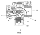
- the illustrated in Figure 5 preferred embodiment of the invention is a metal halide high-pressure discharge lamp with an electrical power consumption of about 35 watts.
- This high-pressure discharge lamp is provided as a light source for a motor vehicle headlight.
- the high-pressure discharge lamp has a discharge vessel 1 made of quartz glass which is sealed on two sides and has two electrodes 2, 3 arranged therein and an ionizable filling containing metal halides for generating a gas discharge.
- the discharge vessel 1 is surrounded by a glass outer bulb 4. Both lamp vessels 1, 4 are fixed in the upper part 51 of a lamp base 5 made of plastic.
- the electrode 2 is electrically contacted by means of the recessed from the base end 11 of the discharge vessel and recirculated to the lamp base 5 power supply 6, while the electrode 3 is electrically contacted by means of protruding from the socket near end 12 of the discharge vessel 1 power supply 7.
- the parallel to the lamp vessels 1, 4 extending gate of the power supply 6 is surrounded by an insulating ceramic tube 61.
- the lamp base 5 has a socket 8 designed as an electrical connection of the high-pressure discharge lamp, which is provided for connecting a shielded cable which connects the high-pressure discharge lamp and the high-pressure discharge lamp ignition device accommodated in the interior of the lamp base 5 to a power supply for the high-pressure discharge lamp and the ignition device ,
- the lamp base 5 is completely surrounded by a two-part metal housing 91, 92, which serves for the electromagnetic shielding of the ignition device accommodated in the lamp base 5. Details of the metal housing 91, 92 are shown schematically in FIG.
- the metal housing 91, 92 is preferably made of aluminum or an aluminum-magnesium alloy or galvanized sheet steel.
- the two housing parts 91, 92 have wall portions 920, 910, which surround the wall of the socket 8 in the mounted state.
- the ignition device is designed as a pulse ignition device and comprises a Zündtransformatoren T1 with primary winding N1 and secondary winding N2 and a firing capacitor C2, a spark gap FS1, two resistors R1, R2, a suppressor diode D1, the voltage inputs J1, J2, J3 and the terminals J4, J5 for the power supply lines 6, 7 of the high-pressure discharge lamp.
- the terminals J1, J2 are used to DC supply the igniter and the terminals J1, J3 serve after completion of the Ignition phase for supplying power to the high-pressure discharge lamp connected to the terminals J4, J5 by means of the operating device connected to the socket 8.
- the terminal J4 is connected to the electrode 3 via the power supply 7, and the terminal J5 is connected to the electrode 2 via the power supply 6.
- the terminal J5 is capacitively coupled to the metal housing 92 of the lamp cap 5 via an electrical network, which in this embodiment consists only of the capacitor C1, for example a ceramic capacitor.
- the ignition capacitor C2 is charged with the aid of the operating device (not shown).
- the voltage across the ignition capacitor C2 reaches the breakdown voltage of the spark gap FS1
- the ignition capacitor C2 discharges and a current flows through the primary winding N1 of the ignition transformer T1 and the spark gap FS1.
- Characterized high voltage pulses are induced in the secondary winding N2 of the ignition transformer T1, which are supplied via the terminal J4 and the power supply 7 of the electrode 3. These high voltage pulses, which have an amplitude of up to 30 kV, ignite the gas discharge between the electrodes 2, 3 in the discharge vessel 1.
- the aforementioned high voltage pulses cause at the power supply 6 and the terminal J5 a so-called kickback voltage of up to 1 kV in the In the circuit shown in Figure 3 and a flyback voltage of up to 1.8 kV in the circuit shown in Figure 4, which is significantly reduced by means of the capacitor C1 and its connection to the metal housing 92 and 920, respectively.
- the suppressor diode D1 is used to limit the voltage at the terminals J1, J3.
- the series circuit of the resistors R1, R2 is connected in parallel with the ignition capacitor C2 and serves to discharge the ignition capacitor C2 after completion of the ignition phase.
- FIG. 1 shows the lead frame 100 for the pulse ignition device according to the first embodiment shown in FIG.
- the planar lead frame 100 serves as a mounting board for the components of the ignition device. It consists of metallic webs (gray areas in Figure 1), which are embedded in an electrically insulating plastic (black areas in Figure 1). With white lines and their reference numerals, the components and terminals of the ignition device of Figure 3 are shown in the representation of the lead frame 100 in Figure 1. Terminals J6, J7 are used to connect the ignition transformer T1.
- the reference numerals X1, X2, X5, X6 denote openings in the lead frame 100, which serve for its installation in the interior of the lamp cap 5.
- the socket 8 is mounted on the lead frame 100.
- a metal web 101 which is connected to one terminal of the capacitor C1 and which is connected at the other end with a wide metallic tongue 102.
- the broad tongue 102 of the metal web 101 projects beyond the lead frame 100 and out of the interior of the lamp base 5 and is arranged in the region of the socket 8.
- the metallic tongue 102 of the metal web 101 is in electrical and mechanical contact with the wall portion 920 of the metal housing 92 of the lamp cap 5, which covers the socket 8.
- FIG. 4 schematically shows the circuit diagram of the second exemplary embodiment of the ignition device accommodated in the interior of the lamp cap 5.
- This ignition device is largely identical to the ignition device of the first embodiment. Therefore, the same reference numerals have been used in Figures 3 and 4 for identical components.
- the ignition device additionally has a radio interference suppression L2 with parallel connected to it air gap. This parallel connection of the inductor L2 and the air gap is connected in the connection between the terminals J3 and J5.
- the air gap arranged parallel to the inductor L2 serves to overvoltage protection of the inductor L2.
- the electrical network for coupling the terminal J5 or the power supply 6 to the metal housing 92 in the second embodiment also consists only of the capacitor C1.
- the capacitor C1 is formed in both embodiments as a ceramic capacitor with a capacity of 500 pF.
- the order of the capacitor C1 and the parallel circuit consisting of the inductor L2 and the air gap can also be reversed so that the terminal J5 is connected to the capacitor C1 via the inductor L2.
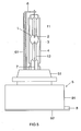
- FIG. 2 shows the lead frame 100 'for the pulse ignition device according to the second embodiment shown in FIG.
- the planar lead frame 100 ' serves as a mounting board for the components of the ignition device according to the second embodiment. It consists of metallic webs (gray areas in Figure 1), which are embedded in an electrically insulating plastic (black areas in Figure 1). With white lines and their reference numerals, the components and terminals of the ignition device of Figure 4 in the representation of the lead frame 100 'in Figure 2 are shown.
- the lead frame 100 'of Figure 2 is largely identical to the lead frame 100 of Figure 1. Therefore, the same reference numerals have been used in Figures 1 and 2 for identical components.
- a metal web 101 'with a wide tongue 102' is arranged, which is connected to one terminal of the capacitor C1.
- the broad tongue 102 'of the metal web 101' which projects beyond the lead frame 100 'and out of the interior of the lamp cap 5, is arranged in the region of the bushing 8.
- the broad tongue of the metal web 101 ' is in electrical and mechanical contact with the wall part 920 of the metal housing 92 of the lamp cap 5.
- the invention is not limited to the embodiments explained in more detail above.
- a suppressor diode having a breakdown voltage of, for example, 200 V can also be used.
- the electrical connection between the capacitor C1 and the metal housing 91, 92 can be carried out instead of the metal tongue 102 or 102 'also with the aid of an electrically conductive rubber on the metal web 101 or 101' of the lead frame 100 or 100 '. rests and rests by a breakthrough in the wall of the lamp cap 5 to the metal housing 91, 92.
- the more complexly shaped metal webs of the lead frame 100 or 100 ', for example, the web between the capacitor C1 and the tongue 102 or 102', may be formed as deep-drawn parts.
Landscapes
- Non-Portable Lighting Devices Or Systems Thereof (AREA)
- Circuit Arrangements For Discharge Lamps (AREA)
- Fastening Of Light Sources Or Lamp Holders (AREA)
- Arrangement Of Elements, Cooling, Sealing, Or The Like Of Lighting Devices (AREA)
- Discharge Lamps And Accessories Thereof (AREA)
Abstract
Description
- Die Erfindung betrifft eine Hochdruckentladungslampe gemäß dem Oberbegriff des Patentanspruchs 1.
- Eine derartige Hochdruckentladungslampe ist beispielsweise in der WO 00/59269 offenbart. Diese Offenlegungsschrift beschreibt eine Hochdruckentladungslampe für einen Kraftfahrzeugscheinwerfer. Die Hochdruckentladungslampe besitzt einen Lampensockel, in dessen Innenraum eine Impulszündvorrichtung zum Zünden der Gasentladung in der Hochdruckentladungslampe angeordnet ist und der von einem auf Massebezugspotential liegenden und zur elektromagnetischen Abschirmung dienenden Metallgehäuse umgeben ist. Außerdem weist die Hochdruckentladungslampe ein Entladungsgefäß auf, das ein sockelnahes und ein sockelfernes Ende besitzt, wobei eine aus dem sockelfernen Ende herausragende Stromzuführung zu dem Lampensockel zurückgeführt ist.
- Zum Zünden der Gasentladung in der Hochdruckentladungslampe wird die aus dem sockelnahen Ende herausgeführte Stromzuführung, die durch die Lampengefäße und den Lampensockel vollständig abgekapselt ist, mittels der Impulszündvorrichtung mit Hochspannungsimpulsen von bis zu 30 kV beaufschlagt. Es hat sich gezeigt, dass während der Zündphase an der aus dem sockelfernen Ende des Entladungsgefäßes herausragenden Stromzuführung ein so genannter Rückschlagimpuls auftritt, der an dem mit der vorgenannten Stromzuführung verbundenen Lampenanschluss einen Spannungsimpuls mit einer Amplitude von ca. 1 kV und einer Impulsdauer von ca. 10 ns verursacht.
- Es ist Aufgabe der Erfindung, eine gattungsgemäße Hochdruckentladungslampe bereitzustellen, die den oben genannten Nachteil nicht mehr aufweist.
- Diese Aufgabe wird erfindungsgemäß durch die Merkmale des Patentanspruchs 1 gelöst. Besonders vorteilhafte Ausführungen der Erfindung sind in den abhängigen Patentansprüchen beschrieben.
- Die erfindungsgemäße Hochdruckentladungslampe besitzt einen Lampensockel, in dessen Innenraum eine Zündvorrichtung zum Zünden der Gasentladung in der Hochdruckentladungslampe angeordnet ist und der mit einer elektromagnetischen Abschirmung versehen ist, und einem Entladungsgefäß, das ein sockelnahes und ein sockelfernes Ende besitzt, wobei eine aus dem sockelfernen Ende des Entladungsgefäßes herausragende Stromzuführung zum Lampensockel zurückgeführt ist. Erfindungsgemäß ist die aus dem sockelfernen Ende des Entladungsgefäßes herausragende Stromzuführung elektrisch an die elektromagnetische Abschirmung gekoppelt ist. Dadurch wird der oben erläuterte Rückschlagimpuls zu der elektromagnetischen Abschirmung abgeleitet und es ist gewährleistet, dass der Rückschlagimpuls an dem mit der aus dem sockelfernen Ende des Entladungsgefäßes herausragenden Stromzuführung verbundenen Lampenanschluss während der Zündphase der Hochdruckentladungslampe keinen nennenswerten Spannungsimpuls verursacht.
- Die elektrische Kopplung der aus dem sockelfernen Ende des Entladungsgefäßes herausragenden Stromzuführung an die elektromagnetische Abschirmung wird vorteilhafter Weise durch eine elektrische Anbindung der vorgenannten Stromzuführung an die elektromagnetische Abschirmung, vorzugsweise mittels eines elektrischen Netzwerks durchgeführt. Dadurch kann die elektrische Anbindung bzw. Kontaktierung vollständig innerhalb der Lampe vorgenommen werden.
- Das vorgenannte elektrische Netzwerk umfasst vorzugsweise mindestens eines der Bauteile aus der Gruppe von Kondensator und Schwellwertschalter oder eine Kombination der Bauteile aus dieser Gruppe. Gemäß der besonders bevorzugten Ausführungsbeispiele umfasst das elektrische Netzwerk nur einen Kondensator.
- Die Komponenten des vorgenannten elektrischen Netzwerks und vorzugsweise auch der Zündvorrichtung sind auf einem Lead-Frame montiert, um eine einfache Montage der Zündvorrichtung und des elektrischen Netzwerks im Innenraum des Lampensockels zu ermöglichen. Das Lead-Frame gewährleistet ferner eine einfache elektrische Kopplung der aus dem sockelfernen Ende des Entladungsgefäßes herausragenden Stromzuführung an die elektromagnetische Abschirmung. Zu diesem Zweck weist das Lead-Frame vorteilhafter Weise einen metallischen Steg auf, der das elektrische Netzwerk mit der elektromagnetischen Abschirmung verbindet.
- Die elektromagnetische Abschirmung ist vorteilhafter Weise als Metallgehäuse ausgebildet, das den Lampensockel zumindest partiell umschließt. Das Metallgehäuse besitzt nur auf der dem Entladungsgefäß zugewandten Seite einen Durchbruch für das Entladungsgefäß bzw. für die Lampengefäße und einen weiteren Durchbruch für den elektrischen Anschluss der Hochdruckentladungslampe, um eine möglichst weitgehende elektromagnetische Abschirmung der im Lampensockel untergebrachten
- Zündvorrichtung zu erzielen.
- Der oben genannte metallische Steg des Lead-Frames ist vorteilhafter Weise derart ausgebildet, dass er im Bereich des elektrischen Anschlusses der Hochdruckentladungslampe aus dem Innenraum des Lampensockels herausragt und mit dem Metallgehäuse in Kontakt steht. Dadurch wird auf einfache Weise ein elektrischer Kontakt zwischen dem elektrischen Netzwerk und dem Metallgehäuse hergestellt. Der metallische Steg kann, ähnlich wie eine Blattfeder, mit Klemmsitz an dem Metallgehäuse anliegen.
- Die erfindungsgemäße Hochdruckentladungslampe bildet zusammen mit einem Betriebsgerät, das zur Energieversorgung der Hochdruckentladungslampe und ihrer im Lampensockel untergebrachten Zündvorrichtung dient, eine Beleuchtungsvorrichtung. Die elektromagnetische Abschirmung des Lampensockels, das heißt, das Metallgehäuse, ist vorzugsweise mit dem Massebezugspotential des Betriebsgerätes verbunden. Bei der Beleuchtungsvorrichtung handelt es sich beispielsweise um einen Fahrzeugscheinwerfer. Die elektromagnetische Abschirmung des Lampensockels bzw. das Metallgehäuse kann zusätzlich über eine Lampenhalterung elektrisch leitend mit dem Reflektor des Fahrzeugscheinwerfers verbunden sein, um auch den dann ebenfalls auf Massepotential befindlichen Reflektor für die elektromagnetische Abschirmung der Hochdruckentladungslampe auszunutzen.
- Nachstehend wird die Erfindung anhand von Ausführungsbeispielen näher erläutert. Es zeigen:
- Figur 1
- Eine schematische Darstellung des Lead-Frames gemäß des ersten Ausführungsbeispiels für die in Figur 3 abgebildete Zündvorrichtung
- Figur 2
- Eine schematische Darstellung des Lead-Frames gemäß des zweiten Ausführungsbeispiels für die in Figur 4 abgebildete Zündvorrichtung
- Figur 3
- Eine Schaltskizze der im Lampensockel untergebrachten Zündvorrichtung gemäß des ersten Ausführungsbeispiels
- Figur 4
- Eine Schaltskizze der im Lampensockel untergebrachten Zündvorrichtung gemäß des zweiten Ausführungsbeispiels
- Figur 5
- Eine Seitenansicht einer Hochdruckentladungslampe gemäß des bevorzugten Ausführungsbeispiels der Erfindung in schematischer Darstellung
- Figur 6
- Eine Seitenansicht des Metallgehäuses des Lampensockels der in Figur 5 abgebildeten Hochdruckentladungslampe
- Bei dem in Figur 5 dargestellten bevorzugten Ausführungsbeispiel der Erfindung handelt es sich um eine Halogen-Metalldampf-Hochdruckentladungslampe mit einer elektrischen Leistungsaufnahme von ca. 35 Watt. Diese Hochdruckentladungslampe ist als Lichtquelle für einen Kraftfahrzeugscheinwerfer vorgesehen. Die Hochdruckentladungslampe besitzt ein zweiseitig abgedichtetes Entladungsgefäß 1 aus Quarzglas mit zwei darin angeordneten Elektroden 2, 3 und einer Metallhalogenide enthaltenden, ionisierbaren Füllung zum Erzeugen einer Gasentladung. Das Entladungsgefäß 1 ist von einem gläsernen Außenkolben 4 umgeben. Beide Lampengefäße 1, 4 sind in dem Oberteil 51 eines aus Kunststoff bestehenden Lampensockels 5 fixiert. Die Elektrode 2 ist mittels der aus dem sockelfernen Ende 11 des Entladungsgefäßes herausragenden und zum Lampensockel 5 zurückgeführten Stromzuführung 6 elektrisch kontaktiert, während die Elektrode 3 mittels der aus dem sockelnahen Ende 12 des Entladungsgefäßes 1 herausragenden Stromzuführung 7 elektrisch kontaktiert ist. Der parallel zu den Lampengefäßen 1, 4 verlaufende Anschnitt der Stromzuführung 6 ist von einem isolierenden Keramikrohr 61 umgeben. Der Lampensockel 5 weist eine als elektrischer Anschluss der Hochdruckentladungslampe ausgebildete Buchse 8 auf, die zum Anschluss eines abgeschirmten Kabels vorgesehen ist, das die Hochdruckentladungslampe und die in dem Innenraum des Lampensockels 5 untergebrachte Zündvorrichtung der Hochdruckentladungslampe mit einem Betriebsgerät zur Spannungsversorgung der Hochdruckentladungslampe und der Zündvorrichtung verbindet. Mit Ausnahme seines Oberteils 51 ist der Lampensockel 5 vollständig von einem zweiteiligen Metallgehäuse 91, 92 umgeben, das zur elektromagnetischen Abschirmung der im Lampensockel 5 untergebrachten Zündvorrichtung dient. Details des Metallgehäuses 91, 92 sind in der Figur 6 schematisch dargestellt. Das Metallgehäuse 91, 92 besteht vorzugsweise aus Aluminium oder einer Aluminium-Magnesium-Legierung oder aus verzinktem Stahlblech. Es besitzt ein deckelartiges Unterteil 92 und ein haubenartiges Oberteil 91 mit einem Durchbruch für die Lampengefäße 1, 4 und für das Sockeloberteil 51. Die beiden Gehäuseteile 91, 92 besitzen Wandbereiche 920, 910, welche im montierten Zustand auch die Wand der Buchse 8 umschließen.
- In Figur 3 ist schematisch die Schaltskizze des ersten Ausführungsbeispiels der im Innenraum des Lampensockels 5 untergebrachten Zündvorrichtung dargestellt. Die Zündvorrichtung ist als Impulszündvorrichtung ausgebildet und umfasst einen Zündtransformator T1 mit Primärwicklung N1 und Sekundärwicklung N2 sowie einen Zündkondensator C2, eine Funkenstrecke FS1, zwei Widerstände R1, R2, eine Suppressordiode D1, die Spannungseingänge J1, J2, J3 und die Anschlüsse J4, J5 für die Stromzuführungen 6, 7 der Hochdruckentladungslampe. Von den Spannungseingängen J1, J2, J3 werden die Anschlüsse J1, J2 zur Gleichspannungsversorgung der Zündvorrichtung genutzt und die Anschlüsse J1, J3 dienen nach Beendigung der Zündphase zur Spannungsversorgung der an die Anschlüsse J4, J5 angeschlossenen Hochdruckentladungslampe mittels des an die Buchse 8 angeschlossenen Betriebsgerätes. Der Anschluss J4 ist über die Stromzuführung 7 mit der Elektrode 3 verbunden und der Anschluss J5 ist über die Stromzuführung 6 mit der Elektrode 2 verbunden. Der Anschluss J5 ist über ein elektrisches Netzwerk, das bei diesem Ausführungsbeispiel nur aus dem Kondensator C1, beispielsweise einem Keramikkondensator, besteht, kapazitiv an das Metallgehäuse 92 des Lampensockels 5 gekoppelt.
- Während der Zündphase der Hochdruckentladungslampe wird mit Hilfe des Betriebsgerätes (nicht abgebildet) der Zündkondensator C2 aufgeladen. Erreicht die Spannung an dem Zündkondensator C2 die Durchbruchsspannung der Funkenstrecke FS1, so entlädt sich der Zündkondensator C2 und es fließt ein Strom über die Primärwicklung N1 des Zündtransformators T1 und die Funkenstrecke FS1. Dadurch werden in der Sekundärwicklung N2 des Zündtransformators T1 Hochspannungsimpulse induziert, die über den Anschluss J4 und die Stromzuführung 7 der Elektrode 3 zugeführt werden. Diese Hochspannungsimpulse, die eine Amplitude von bis zu 30 kV besitzen, zünden die Gasentladung zwischen den Elektroden 2, 3 in dem Entladungsgefäß 1. Die vorgenannten Hochspannungsimpulse verursachen an der Stromzuführung 6 und dem Anschluss J5 eine so genannte Rückschlagspannung von bis zu 1 kV bei der in Figur 3 dargestellten Schaltung und eine Rückschlagspannung von bis zu 1,8 kV bei der in Figur 4 dargestellten Schaltung, die mittels des Kondensators C1 und seiner Verbindung zum Metallgehäuse 92 bzw. 920 erheblich reduziert wird. Die Suppressordiode D1 dient zur Spannungsbegrenzung an den Anschlüssen J1, J3. Die Serienschaltung der Widerstände R1, R2 ist parallel zum Zündkondensator C2 geschaltet und dient zum Entladen des Zündkondensators C2 nach Beendigung der Zündphase.
- In der Figur 1 ist das Lead-Frame 100 für die in Figur 3 dargestellte Impulszündvorrichtung gemäß des ersten Ausführungsbeispiels abgebildet. Das ebene Lead-Frame 100 dient als Montageplatine für die Komponenten der Zündvorrichtung. Es besteht aus metallischen Stegen (graue Flächen in Figur 1), die in einen elektrisch isolierenden Kunststoff (schwarze Flächen in Figur 1) eingebettet sind. Mit weißen Linien und ihren Bezugszeichen sind die Komponenten und Anschlüsse der Zündvorrichtung aus Figur 3 in die Darstellung des Lead-Frames 100 in Figur 1 eingezeichnet. Die Anschlüsse J6, J7 dienen zum Anschluss des Zündtransformators T1. Die Bezugszeichen X1, X2, X5, X6 bezeichnen Durchbrüche im Lead-Frame 100, die zu seiner Montage im Innenraum des Lampensockels 5 dienen. Die Buchse 8 ist auf das Lead-Frame 100 montiert. In den Bereich der Buchse 8 erstreckt sich ein Metallsteg 101, der mit einem Anschluss des Kondensators C1 verbunden ist und der am anderen Ende mit einer breiten metallischen Zunge 102 verbunden ist. Die breite Zunge 102 des Metallstegs 101 ragt über das Lead-Frame 100 und aus dem Innenraum des Lampensockels 5 hinaus und ist im Bereich der Buchse 8 angeordnet. Im montierten Zustand befindet sich die metallische Zunge 102 des Metallstegs 101 im elektrischen und mechanischen Kontakt mit dem Wandteil 920 des Metallgehäuses 92 des Lampensockels 5, das die Buchse 8 abdeckt.
- In Figur 4 ist schematisch die Schaltskizze des zweiten Ausführungsbeispiels der im Innenraum des Lampensockels 5 untergebrachten Zündvorrichtung dargestellt. Diese Zündvorrichtung ist weitgehend identisch zur Zündvorrichtung des ersten Ausführungsbeispiels. Daher wurden in den Figuren 3 und 4 für identische Bauteile dieselben Bezugszeichen verwendet. Beim zweiten Ausführungsbeispiel besitzt die Zündvorrichtung zusätzlich eine Funkentstördrossel L2 mit parallel dazu geschalteter Luftfunkenstrecke. Diese Parallelschaltung der Drossel L2 und der Luftfunkenstrecke ist in die Verbindung zwischen die Anschlüsse J3 und J5 geschaltet. Die parallel zur Drossel L2 angeordneten Luftfunkenstrecke dient zum Überspannungsschutz der Drossel L2. Das elektrische Netzwerk zur Kopplung des Anschlusses J5 bzw. der Stromzuführung 6 an das Metallgehäuse 92 besteht bei dem zweiten Ausführungsbeispiel ebenfalls nur aus dem Kondensator C1. Der Kondensator C1 ist bei beiden Ausführungsbeispielen als Keramikkondensator mit einer Kapazität von 500 pF ausgebildet. In der in Figur 4 dargestellten Schaltung kann die Reihenfolge des Kondensators C1 und der aus der Drossel L2 und der Luftfunkenstrecke bestehenden Parallelschaltung auch vertauscht werden, so dass der Anschluss J5 über die Drossel L2 mit dem Kondensator C1 verbunden ist.
- In der Figur 2 ist das Lead-Frame 100' für die in Figur 4 dargestellte Impulszündvorrichtung gemäß des zweiten Ausführungsbeispiels abgebildet. Das ebene Lead-Frame 100' dient als Montageplatine für die Komponenten der Zündvorrichtung gemäß des zweiten Ausführungsbeispiels. Es besteht aus metallischen Stegen (graue Flächen in Figur 1), die in einen elektrisch isolierenden Kunststoff (schwarze Flächen in Figur 1) eingebettet sind. Mit weißen Linien und ihren Bezugszeichen sind die Komponenten und Anschlüsse der Zündvorrichtung aus Figur 4 in die Darstellung des Lead-Frames 100' in Figur 2 eingezeichnet. Das Lead-Frame 100' aus Figur 2 ist weitgehend identisch mit dem Lead-Frame 100 aus Figur 1. Daher wurden in den Figuren 1 und 2 für identische Komponenten dieselben Bezugszeichen verwendet. Im Bereich der Buchse 8 ist ein Metallsteg 101' mit einer breiten Zunge 102' angeordnet, der mit einem Anschluss des Kondensators C1 verbunden ist. Die breite Zunge 102' des Metallstegs 101', die über das Lead-Frame 100' und aus dem Innenraum des Lampensockels 5 hinausragt, ist im Bereich der Buchse 8 angeordnet. Im montierten Zustand befindet sich die breite Zunge des Metallstegs 101' im elektrischen und mechanischen Kontakt mit dem Wandteil 920 des Metallgehäuses 92 des Lampensockels 5.
- Die Erfindung beschränkt sich nicht auf die oben näher erläuterten Ausführungsbeispiele. Beispielsweise kann anstelle des Kondensators C1 in den in Figur 3 und 4 dargestellten Ausführungsbeispielen auch eine Suppressordiode mit einer Durchbruchsspannung von beispielsweise 200 V verwendet werden. Die elektrische Verbindung zwischen dem Kondensator C1 und dem Metallgehäuse 91, 92 kann anstelle der Metallzunge 102 bzw. 102' auch mit Hilfe eines elektrisch leitfähigen Gummis durchgeführt werden, das auf dem Metallsteg 101 bzw. 101' des Lead-Frames 100 bzw. 100' aufliegt und durch einen Durchbruch in der Wand des Lampensockels 5 an dem Metallgehäuse 91, 92 anliegt. Die komplexer geformten Metallstege des Lead-Frames 100 bzw. 100', beispielsweise der Steg zwischen dem Kondensator C1 und der Zunge 102 bzw. 102', können als Tiefziehteile ausgebildet sein.
Claims (10)
- Hochdruckentladungslampe mit einem Lampensockel (5), in dessen Innenraum eine Zündvorrichtung zum Zünden der Gasentladung in der Hochdruckentladungslampe angeordnet ist und der mit einer elektromagnetischen Abschirmung (91, 92) versehen ist, und einem Entladungsgefäß (1), das ein sockelnahes (12) und ein sockelfernes Ende (11) besitzt, wobei eine aus dem sockelfernen Ende (11) des Entladungsgefäßes (1) herausragende Stromzuführung (6) zum Lampensockel (5) zurückgeführt ist, dadurch gekennzeichnet, dass die aus dem sockelfernen Ende (11) des Entladungsgefäßes (1) herausragende Stromzuführung (6) elektrisch an die elektromagnetische Abschirmung (91, 92) gekoppelt ist.
- Hochdruckentladungslampe nach Anspruch 1, dadurch gekennzeichnet, dass die aus dem sockelfernen Ende (11) des Entladungsgefäßes (1) herausragende Stromzuführung (6) mittels eines elektrischen Netzwerks (C1) an die elektromagnetische Abschirmung (91, 92) gekoppelt ist.
- Hochdruckentladungslampe nach Anspruch 2, dadurch gekennzeichnet, dass das elektrische Netzwerk mindestens einen Kondensator (C1) umfasst.
- Hochdruckentladungslampe nach Anspruch 2 oder 3, dadurch gekennzeichnet, dass das elektrische Netzwerk mindestens einen Schwellwertschalter umfasst.
- Hochdruckentladungslampe nach einem oder mehreren der Ansprüche 1 bis 4, dadurch gekennzeichnet, dass die Komponenten des elektrischen Netzwerks (C1) auf einem Lead-Frame (100) montiert sind.
- Hochdruckentladungslampe nach Anspruch 1, dadurch gekennzeichnet, dass die Komponenten der Zündvorrichtung auf einem Lead-Frame (100) montiert sind.
- Hochdruckentladungslampe nach Anspruch 5 oder 6, dadurch gekennzeichnet, dass das Lead-Frame (100) einen metallischen Steg (101, 102) aufweist, der das elektrische Netzwerk (C1) bzw. die aus dem sockelfernen Ende (11) des Entladungsgefäßes (1) herausragende Stromzuführung (6) mit der elektromagnetischen Abschirmung (91, 92) elektrisch leitend verbindet.
- Hochdruckentladungslampe nach einem oder mehreren der Ansprüche 1 bis 7, dadurch gekennzeichnet, dass die elektromagnetische Abschirmung als Metallgehäuse (91, 92) ausgebildet ist, das den Lampensockel (5) zumindest partiell umschließt.
- Hochdruckentladungslampe nach Anspruch 8, dadurch gekennzeichnet, dass der metallische Steg (101, 102) aus dem Innenraum des Lampensockels (5) herausgeführt ist und im Bereich eines elektrischen Anschlusses (8) der Hochdruckentladungslampe mit dem Metallgehäuse (91, 92) in Kontakt steht.
- Beleuchtungsvorrichtung, insbesondere Fahrzeugscheinwerfer, mit einer Hochdruckentladungslampe gemäß einem oder mehreren der Ansprüche 1 bis 9 und einem Betriebsgerät für die Hochdruckentladungslampe, wobei die elektromagnetische Abschirmung (91, 92) mit dem Massebezugspotential des Betriebsgerätes verbunden ist.
Applications Claiming Priority (1)
| Application Number | Priority Date | Filing Date | Title |
|---|---|---|---|
| DE102004058881A DE102004058881A1 (de) | 2004-12-06 | 2004-12-06 | Hochdruckentladungslampe und Beleuchtungsvorrichtung mit Hochdruckentladungslampe |
Publications (3)
| Publication Number | Publication Date |
|---|---|
| EP1667200A2 true EP1667200A2 (de) | 2006-06-07 |
| EP1667200A3 EP1667200A3 (de) | 2007-05-30 |
| EP1667200B1 EP1667200B1 (de) | 2009-08-12 |
Family
ID=35851686
Family Applications (1)
| Application Number | Title | Priority Date | Filing Date |
|---|---|---|---|
| EP05025752A Expired - Lifetime EP1667200B1 (de) | 2004-12-06 | 2005-11-25 | Hochdruckentladungslampe und Beleuchtungsvorrichtung mit Hochdruckentladungslampe |
Country Status (7)
| Country | Link |
|---|---|
| US (1) | US7453213B2 (de) |
| EP (1) | EP1667200B1 (de) |
| JP (1) | JP4956830B2 (de) |
| CN (1) | CN1798465A (de) |
| AT (1) | ATE439680T1 (de) |
| DE (2) | DE102004058881A1 (de) |
| ES (1) | ES2328490T3 (de) |
Families Citing this family (7)
| Publication number | Priority date | Publication date | Assignee | Title |
|---|---|---|---|---|
| JP4913001B2 (ja) * | 2007-09-28 | 2012-04-11 | 株式会社オーク製作所 | 光源装置 |
| FR2922078B1 (fr) * | 2007-10-08 | 2011-04-15 | Valeo Vision | Module electronique comportant un connecteur blinde fixe sur une carte a circuit integre par l'intermediaire d'une patte de fixation du blindage |
| DE102009018448A1 (de) * | 2009-04-22 | 2010-10-28 | Automotive Lighting Reutlingen Gmbh | Beleuchtungseinrichtung eines Kraftfahrzeugs |
| US20100304810A1 (en) * | 2009-05-29 | 2010-12-02 | Harmonix Music Systems, Inc. | Displaying A Harmonically Relevant Pitch Guide |
| JP5841692B2 (ja) | 2012-04-26 | 2016-01-13 | コーニンクレッカ フィリップス エヌ ヴェKoninklijke Philips N.V. | ベース内に接点路を備える放電ランプ |
| JP5851069B2 (ja) * | 2012-04-26 | 2016-02-03 | コーニンクレッカ フィリップス エヌ ヴェKoninklijke Philips N.V. | ランプハウジングへのグランド接続 |
| JP6178087B2 (ja) * | 2013-03-14 | 2017-08-09 | 浜松ホトニクス株式会社 | フラッシュ光源装置 |
Citations (3)
| Publication number | Priority date | Publication date | Assignee | Title |
|---|---|---|---|---|
| DE19610388A1 (de) | 1996-03-16 | 1997-09-18 | Bosch Gmbh Robert | Zündeinrichtung für eine Entladungslampe |
| WO2000059269A1 (de) | 1999-03-26 | 2000-10-05 | Vogt Electronic Ag | Gasentladungslampensockel mit zündeinrichtung |
| WO2004083900A2 (en) | 2003-03-18 | 2004-09-30 | Philips Intellectual Property & Standards Gmbh | Gas discharge lamp |
Family Cites Families (13)
| Publication number | Priority date | Publication date | Assignee | Title |
|---|---|---|---|---|
| DE4014745A1 (de) * | 1990-05-08 | 1991-11-14 | Patent Treuhand Ges Fuer Elektrische Gluehlampen Mbh | Einseitig gesockelte elektrische lampe |
| JPH0686538A (ja) * | 1992-08-31 | 1994-03-25 | Toshiba Lighting & Technol Corp | 電源装置、放電灯点灯装置および照明器具 |
| US5485057A (en) * | 1993-09-02 | 1996-01-16 | Smallwood; Robert C. | Gas discharge lamp and power distribution system therefor |
| US6066921A (en) * | 1995-02-28 | 2000-05-23 | Matsushita Electric Works, Ltd. | Discharge lamp lighting device |
| JP3463482B2 (ja) * | 1996-09-30 | 2003-11-05 | 松下電工株式会社 | 放電灯点灯装置 |
| US6084354A (en) * | 1997-03-06 | 2000-07-04 | Ngk Spark Plug Co., Ltd. | Vehicle-lamp lighting-on device |
| JPH11162667A (ja) * | 1997-11-28 | 1999-06-18 | Toshiba Lighting & Technology Corp | 高圧放電灯点灯装置 |
| JP2000023451A (ja) * | 1998-06-30 | 2000-01-21 | Toshiba Lighting & Technology Corp | 電源装置、放電灯点灯装置および照明装置 |
| DE19831042A1 (de) * | 1998-07-13 | 2000-02-17 | Patent Treuhand Ges Fuer Elektrische Gluehlampen Mbh | Beleuchtungssystem mit einer Hochdruckentladungslampe |
| JP3962889B2 (ja) * | 1999-11-25 | 2007-08-22 | 東洋電装株式会社 | Hidランプ点灯装置 |
| TW503339B (en) | 2001-10-25 | 2002-09-21 | Primax Electronics Ltd | Camera with a focus retaining mechanism |
| JP4043926B2 (ja) * | 2002-11-28 | 2008-02-06 | 株式会社小糸製作所 | 車輌用前照灯 |
| DE10339587A1 (de) * | 2003-08-26 | 2005-03-24 | Patent-Treuhand-Gesellschaft für elektrische Glühlampen mbH | Transformator, Lampensockel mit einem Transformator und Hochdruckentladungslampe |
-
2004
- 2004-12-06 DE DE102004058881A patent/DE102004058881A1/de not_active Withdrawn
-
2005
- 2005-11-25 DE DE502005007884T patent/DE502005007884D1/de not_active Expired - Lifetime
- 2005-11-25 ES ES05025752T patent/ES2328490T3/es not_active Expired - Lifetime
- 2005-11-25 EP EP05025752A patent/EP1667200B1/de not_active Expired - Lifetime
- 2005-11-25 AT AT05025752T patent/ATE439680T1/de not_active IP Right Cessation
- 2005-11-30 US US11/289,430 patent/US7453213B2/en not_active Expired - Fee Related
- 2005-12-06 JP JP2005352513A patent/JP4956830B2/ja not_active Expired - Fee Related
- 2005-12-06 CN CNA2005100034600A patent/CN1798465A/zh active Pending
Patent Citations (3)
| Publication number | Priority date | Publication date | Assignee | Title |
|---|---|---|---|---|
| DE19610388A1 (de) | 1996-03-16 | 1997-09-18 | Bosch Gmbh Robert | Zündeinrichtung für eine Entladungslampe |
| WO2000059269A1 (de) | 1999-03-26 | 2000-10-05 | Vogt Electronic Ag | Gasentladungslampensockel mit zündeinrichtung |
| WO2004083900A2 (en) | 2003-03-18 | 2004-09-30 | Philips Intellectual Property & Standards Gmbh | Gas discharge lamp |
Also Published As
| Publication number | Publication date |
|---|---|
| CN1798465A (zh) | 2006-07-05 |
| EP1667200B1 (de) | 2009-08-12 |
| US20060119282A1 (en) | 2006-06-08 |
| DE102004058881A1 (de) | 2006-06-08 |
| JP2006164982A (ja) | 2006-06-22 |
| ATE439680T1 (de) | 2009-08-15 |
| JP4956830B2 (ja) | 2012-06-20 |
| DE502005007884D1 (de) | 2009-09-24 |
| US7453213B2 (en) | 2008-11-18 |
| ES2328490T3 (es) | 2009-11-13 |
| EP1667200A3 (de) | 2007-05-30 |
Similar Documents
| Publication | Publication Date | Title |
|---|---|---|
| DE60319452T2 (de) | Entladungslampe | |
| DE19831042A1 (de) | Beleuchtungssystem mit einer Hochdruckentladungslampe | |
| EP1635619B1 (de) | Hochdruckentladungslampe mit Transformator | |
| EP1667200B1 (de) | Hochdruckentladungslampe und Beleuchtungsvorrichtung mit Hochdruckentladungslampe | |
| EP1033906B1 (de) | Einseitig gesockelte Hochdruckentladungslampe mit im Sockel integrierter Zündvorrichtung | |
| EP1659835B1 (de) | Hochdruckentladungslampe mit Impulszündvorrichtung und Betriebsverfahren für eine Hochdruckentladungslampe | |
| EP1880449B1 (de) | Lampensockel und hochdruckentladungslampe mit einem lampensockel | |
| DE10133326A1 (de) | Dielektrische Barrieren-Entladungslampe mit Zündhilfe | |
| EP2499427B1 (de) | Hochdruckentladungslampe | |
| DE60208473T2 (de) | Entladungslampenanordnung | |
| WO2010025770A1 (de) | Entladungslampe | |
| EP0933974A1 (de) | Zuendvorrichtung für eine Entladungslampe | |
| WO2006076879A1 (de) | Hochdruckentladungslampe | |
| EP2754166B1 (de) | Baugruppe für eine entladungslampe und entladungslampe | |
| EP1658661B1 (de) | Lampensockel für eine hochdruckentladungslampe und hochdruck entladungslampe | |
| EP1496725A2 (de) | Zündvorrichtung mit einem piezoelektrischen Transformator für eine Hochdruckentladungslampe | |
| WO2013017325A1 (de) | Hochdruckentladungslampe mit zündhilfe und betriebsvorrichtung | |
| DE10331437A1 (de) | Hochdruckentladungslampe mit integrierter Zündvorrichtung und Fahrzeugscheinwerfer mit einer Hochdruckentladungslampe | |
| EP0595333A1 (de) | Zündschaltung für eine Hochdruckmetalldampfentladungslampe | |
| WO2007057309A1 (de) | Hochdruckentladungslampe | |
| DE102008009144A1 (de) | Verfahren zum Zünden der Gasentladung in einer Hochdruckentladungslampe | |
| EP1602879A2 (de) | Scheinwerfer für Fahrzeuge mit abgeschirmeten Gehäuse für die Vorschalteinrichtung der Gasentladungslampe | |
| DE202012011490U1 (de) | Hochdruckentladungslampe | |
| DE102005060797A1 (de) | Vorrichtung zur Verbesserung der elektromagnetischen Verträglichkeit einer Hochdruckentladungslampe | |
| DE102005023798A1 (de) | Vorrichtung zum Betreiben oder Zünden einer Hochdruckentladungslampe, Lampensockel und Beleuchtungssystem mit einer derartigen Vorrichtung sowie Verfahren zum Betreiben einer Hochdruckentladungslampe |
Legal Events
| Date | Code | Title | Description |
|---|---|---|---|
| PUAI | Public reference made under article 153(3) epc to a published international application that has entered the european phase |
Free format text: ORIGINAL CODE: 0009012 |
|
| AK | Designated contracting states |
Kind code of ref document: A2 Designated state(s): AT BE BG CH CY CZ DE DK EE ES FI FR GB GR HU IE IS IT LI LT LU LV MC NL PL PT RO SE SI SK TR |
|
| AX | Request for extension of the european patent |
Extension state: AL BA HR MK YU |
|
| PUAL | Search report despatched |
Free format text: ORIGINAL CODE: 0009013 |
|
| AK | Designated contracting states |
Kind code of ref document: A3 Designated state(s): AT BE BG CH CY CZ DE DK EE ES FI FR GB GR HU IE IS IT LI LT LU LV MC NL PL PT RO SE SI SK TR |
|
| AX | Request for extension of the european patent |
Extension state: AL BA HR MK YU |
|
| RIC1 | Information provided on ipc code assigned before grant |
Ipc: H01J 61/56 20060101AFI20070424BHEP Ipc: H05B 41/02 20060101ALN20070424BHEP |
|
| 17P | Request for examination filed |
Effective date: 20070621 |
|
| 17Q | First examination report despatched |
Effective date: 20070719 |
|
| AKX | Designation fees paid |
Designated state(s): AT BE BG CH CY CZ DE DK EE ES FI FR GB GR HU IE IS IT LI LT LU LV MC NL PL PT RO SE SI SK TR |
|
| GRAP | Despatch of communication of intention to grant a patent |
Free format text: ORIGINAL CODE: EPIDOSNIGR1 |
|
| RAP1 | Party data changed (applicant data changed or rights of an application transferred) |
Owner name: OSRAM GESELLSCHAFT MIT BESCHRAENKTER HAFTUNG |
|
| GRAS | Grant fee paid |
Free format text: ORIGINAL CODE: EPIDOSNIGR3 |
|
| GRAA | (expected) grant |
Free format text: ORIGINAL CODE: 0009210 |
|
| AK | Designated contracting states |
Kind code of ref document: B1 Designated state(s): AT BE BG CH CY CZ DE DK EE ES FI FR GB GR HU IE IS IT LI LT LU LV MC NL PL PT RO SE SI SK TR |
|
| REG | Reference to a national code |
Ref country code: GB Ref legal event code: FG4D Free format text: NOT ENGLISH |
|
| REG | Reference to a national code |
Ref country code: CH Ref legal event code: EP |
|
| REG | Reference to a national code |
Ref country code: IE Ref legal event code: FG4D |
|
| REF | Corresponds to: |
Ref document number: 502005007884 Country of ref document: DE Date of ref document: 20090924 Kind code of ref document: P |
|
| REG | Reference to a national code |
Ref country code: SE Ref legal event code: TRGR |
|
| REG | Reference to a national code |
Ref country code: ES Ref legal event code: FG2A Ref document number: 2328490 Country of ref document: ES Kind code of ref document: T3 |
|
| LTIE | Lt: invalidation of european patent or patent extension |
Effective date: 20090812 |
|
| REG | Reference to a national code |
Ref country code: HU Ref legal event code: AG4A Ref document number: E006391 Country of ref document: HU |
|
| PG25 | Lapsed in a contracting state [announced via postgrant information from national office to epo] |
Ref country code: LT Free format text: LAPSE BECAUSE OF FAILURE TO SUBMIT A TRANSLATION OF THE DESCRIPTION OR TO PAY THE FEE WITHIN THE PRESCRIBED TIME-LIMIT Effective date: 20090812 Ref country code: IS Free format text: LAPSE BECAUSE OF FAILURE TO SUBMIT A TRANSLATION OF THE DESCRIPTION OR TO PAY THE FEE WITHIN THE PRESCRIBED TIME-LIMIT Effective date: 20091212 Ref country code: FI Free format text: LAPSE BECAUSE OF FAILURE TO SUBMIT A TRANSLATION OF THE DESCRIPTION OR TO PAY THE FEE WITHIN THE PRESCRIBED TIME-LIMIT Effective date: 20090812 |
|
| PG25 | Lapsed in a contracting state [announced via postgrant information from national office to epo] |
Ref country code: PL Free format text: LAPSE BECAUSE OF FAILURE TO SUBMIT A TRANSLATION OF THE DESCRIPTION OR TO PAY THE FEE WITHIN THE PRESCRIBED TIME-LIMIT Effective date: 20090812 Ref country code: SI Free format text: LAPSE BECAUSE OF FAILURE TO SUBMIT A TRANSLATION OF THE DESCRIPTION OR TO PAY THE FEE WITHIN THE PRESCRIBED TIME-LIMIT Effective date: 20090812 Ref country code: LV Free format text: LAPSE BECAUSE OF FAILURE TO SUBMIT A TRANSLATION OF THE DESCRIPTION OR TO PAY THE FEE WITHIN THE PRESCRIBED TIME-LIMIT Effective date: 20090812 |
|
| REG | Reference to a national code |
Ref country code: IE Ref legal event code: FD4D |
|
| PG25 | Lapsed in a contracting state [announced via postgrant information from national office to epo] |
Ref country code: BG Free format text: LAPSE BECAUSE OF FAILURE TO SUBMIT A TRANSLATION OF THE DESCRIPTION OR TO PAY THE FEE WITHIN THE PRESCRIBED TIME-LIMIT Effective date: 20091112 Ref country code: PT Free format text: LAPSE BECAUSE OF FAILURE TO SUBMIT A TRANSLATION OF THE DESCRIPTION OR TO PAY THE FEE WITHIN THE PRESCRIBED TIME-LIMIT Effective date: 20091212 |
|
| PG25 | Lapsed in a contracting state [announced via postgrant information from national office to epo] |
Ref country code: RO Free format text: LAPSE BECAUSE OF FAILURE TO SUBMIT A TRANSLATION OF THE DESCRIPTION OR TO PAY THE FEE WITHIN THE PRESCRIBED TIME-LIMIT Effective date: 20090812 Ref country code: CZ Free format text: LAPSE BECAUSE OF FAILURE TO SUBMIT A TRANSLATION OF THE DESCRIPTION OR TO PAY THE FEE WITHIN THE PRESCRIBED TIME-LIMIT Effective date: 20090812 Ref country code: IE Free format text: LAPSE BECAUSE OF FAILURE TO SUBMIT A TRANSLATION OF THE DESCRIPTION OR TO PAY THE FEE WITHIN THE PRESCRIBED TIME-LIMIT Effective date: 20090812 Ref country code: EE Free format text: LAPSE BECAUSE OF FAILURE TO SUBMIT A TRANSLATION OF THE DESCRIPTION OR TO PAY THE FEE WITHIN THE PRESCRIBED TIME-LIMIT Effective date: 20090812 Ref country code: DK Free format text: LAPSE BECAUSE OF FAILURE TO SUBMIT A TRANSLATION OF THE DESCRIPTION OR TO PAY THE FEE WITHIN THE PRESCRIBED TIME-LIMIT Effective date: 20090812 |
|
| PG25 | Lapsed in a contracting state [announced via postgrant information from national office to epo] |
Ref country code: SK Free format text: LAPSE BECAUSE OF FAILURE TO SUBMIT A TRANSLATION OF THE DESCRIPTION OR TO PAY THE FEE WITHIN THE PRESCRIBED TIME-LIMIT Effective date: 20090812 |
|
| PLBE | No opposition filed within time limit |
Free format text: ORIGINAL CODE: 0009261 |
|
| STAA | Information on the status of an ep patent application or granted ep patent |
Free format text: STATUS: NO OPPOSITION FILED WITHIN TIME LIMIT |
|
| PG25 | Lapsed in a contracting state [announced via postgrant information from national office to epo] |
Ref country code: MC Free format text: LAPSE BECAUSE OF NON-PAYMENT OF DUE FEES Effective date: 20091130 |
|
| REG | Reference to a national code |
Ref country code: CH Ref legal event code: PL |
|
| 26N | No opposition filed |
Effective date: 20100517 |
|
| PG25 | Lapsed in a contracting state [announced via postgrant information from national office to epo] |
Ref country code: CH Free format text: LAPSE BECAUSE OF NON-PAYMENT OF DUE FEES Effective date: 20091130 Ref country code: GR Free format text: LAPSE BECAUSE OF FAILURE TO SUBMIT A TRANSLATION OF THE DESCRIPTION OR TO PAY THE FEE WITHIN THE PRESCRIBED TIME-LIMIT Effective date: 20091113 Ref country code: LI Free format text: LAPSE BECAUSE OF NON-PAYMENT OF DUE FEES Effective date: 20091130 |
|
| PG25 | Lapsed in a contracting state [announced via postgrant information from national office to epo] |
Ref country code: AT Free format text: LAPSE BECAUSE OF NON-PAYMENT OF DUE FEES Effective date: 20091125 |
|
| PGFP | Annual fee paid to national office [announced via postgrant information from national office to epo] |
Ref country code: NL Payment date: 20101111 Year of fee payment: 6 |
|
| PGFP | Annual fee paid to national office [announced via postgrant information from national office to epo] |
Ref country code: IT Payment date: 20101125 Year of fee payment: 6 |
|
| PG25 | Lapsed in a contracting state [announced via postgrant information from national office to epo] |
Ref country code: LU Free format text: LAPSE BECAUSE OF NON-PAYMENT OF DUE FEES Effective date: 20091125 |
|
| PGFP | Annual fee paid to national office [announced via postgrant information from national office to epo] |
Ref country code: HU Payment date: 20110117 Year of fee payment: 6 |
|
| PG25 | Lapsed in a contracting state [announced via postgrant information from national office to epo] |
Ref country code: TR Free format text: LAPSE BECAUSE OF FAILURE TO SUBMIT A TRANSLATION OF THE DESCRIPTION OR TO PAY THE FEE WITHIN THE PRESCRIBED TIME-LIMIT Effective date: 20090812 |
|
| PG25 | Lapsed in a contracting state [announced via postgrant information from national office to epo] |
Ref country code: CY Free format text: LAPSE BECAUSE OF FAILURE TO SUBMIT A TRANSLATION OF THE DESCRIPTION OR TO PAY THE FEE WITHIN THE PRESCRIBED TIME-LIMIT Effective date: 20090812 |
|
| PGFP | Annual fee paid to national office [announced via postgrant information from national office to epo] |
Ref country code: SE Payment date: 20111117 Year of fee payment: 7 |
|
| REG | Reference to a national code |
Ref country code: DE Ref legal event code: R081 Ref document number: 502005007884 Country of ref document: DE Owner name: OSRAM GMBH, DE Free format text: FORMER OWNER: OSRAM GESELLSCHAFT MIT BESCHRAENKTER HAFTUNG, 81543 MUENCHEN, DE Effective date: 20111213 |
|
| PGFP | Annual fee paid to national office [announced via postgrant information from national office to epo] |
Ref country code: BE Payment date: 20111229 Year of fee payment: 7 |
|
| REG | Reference to a national code |
Ref country code: NL Ref legal event code: V1 Effective date: 20120601 |
|
| PG25 | Lapsed in a contracting state [announced via postgrant information from national office to epo] |
Ref country code: HU Free format text: LAPSE BECAUSE OF NON-PAYMENT OF DUE FEES Effective date: 20111126 Ref country code: NL Free format text: LAPSE BECAUSE OF NON-PAYMENT OF DUE FEES Effective date: 20120601 |
|
| PG25 | Lapsed in a contracting state [announced via postgrant information from national office to epo] |
Ref country code: IT Free format text: LAPSE BECAUSE OF NON-PAYMENT OF DUE FEES Effective date: 20111125 |
|
| REG | Reference to a national code |
Ref country code: DE Ref legal event code: R081 Ref document number: 502005007884 Country of ref document: DE Owner name: OSRAM GMBH, DE Free format text: FORMER OWNER: OSRAM AG, 81543 MUENCHEN, DE Effective date: 20130205 |
|
| BERE | Be: lapsed |
Owner name: OSRAM G.M.B.H. Effective date: 20121130 |
|
| PG25 | Lapsed in a contracting state [announced via postgrant information from national office to epo] |
Ref country code: SE Free format text: LAPSE BECAUSE OF NON-PAYMENT OF DUE FEES Effective date: 20121126 |
|
| PG25 | Lapsed in a contracting state [announced via postgrant information from national office to epo] |
Ref country code: BE Free format text: LAPSE BECAUSE OF NON-PAYMENT OF DUE FEES Effective date: 20121130 |
|
| REG | Reference to a national code |
Ref country code: DE Ref legal event code: R081 Ref document number: 502005007884 Country of ref document: DE Owner name: OSRAM GMBH, DE Free format text: FORMER OWNER: OSRAM GMBH, 81543 MUENCHEN, DE Effective date: 20130823 |
|
| REG | Reference to a national code |
Ref country code: FR Ref legal event code: PLFP Year of fee payment: 11 |
|
| REG | Reference to a national code |
Ref country code: FR Ref legal event code: PLFP Year of fee payment: 12 |
|
| REG | Reference to a national code |
Ref country code: FR Ref legal event code: PLFP Year of fee payment: 13 |
|
| PGFP | Annual fee paid to national office [announced via postgrant information from national office to epo] |
Ref country code: DE Payment date: 20171121 Year of fee payment: 13 Ref country code: FR Payment date: 20171121 Year of fee payment: 13 |
|
| PGFP | Annual fee paid to national office [announced via postgrant information from national office to epo] |
Ref country code: ES Payment date: 20171220 Year of fee payment: 13 Ref country code: GB Payment date: 20171123 Year of fee payment: 13 |
|
| REG | Reference to a national code |
Ref country code: DE Ref legal event code: R119 Ref document number: 502005007884 Country of ref document: DE |
|
| GBPC | Gb: european patent ceased through non-payment of renewal fee |
Effective date: 20181125 |
|
| PG25 | Lapsed in a contracting state [announced via postgrant information from national office to epo] |
Ref country code: FR Free format text: LAPSE BECAUSE OF NON-PAYMENT OF DUE FEES Effective date: 20181130 Ref country code: DE Free format text: LAPSE BECAUSE OF NON-PAYMENT OF DUE FEES Effective date: 20190601 |
|
| PG25 | Lapsed in a contracting state [announced via postgrant information from national office to epo] |
Ref country code: GB Free format text: LAPSE BECAUSE OF NON-PAYMENT OF DUE FEES Effective date: 20181125 |
|
| REG | Reference to a national code |
Ref country code: ES Ref legal event code: FD2A Effective date: 20200108 |
|
| PG25 | Lapsed in a contracting state [announced via postgrant information from national office to epo] |
Ref country code: ES Free format text: LAPSE BECAUSE OF NON-PAYMENT OF DUE FEES Effective date: 20181126 |