EP1667496A1 - Dispositif de retroeclairage et unite d'affichage le comprenant - Google Patents
Dispositif de retroeclairage et unite d'affichage le comprenant Download PDFInfo
- Publication number
- EP1667496A1 EP1667496A1 EP04773135A EP04773135A EP1667496A1 EP 1667496 A1 EP1667496 A1 EP 1667496A1 EP 04773135 A EP04773135 A EP 04773135A EP 04773135 A EP04773135 A EP 04773135A EP 1667496 A1 EP1667496 A1 EP 1667496A1
- Authority
- EP
- European Patent Office
- Prior art keywords
- synchronous signal
- light source
- source group
- light sources
- light
- Prior art date
- Legal status (The legal status is an assumption and is not a legal conclusion. Google has not performed a legal analysis and makes no representation as to the accuracy of the status listed.)
- Withdrawn
Links
Images







Classifications
-
- H—ELECTRICITY
- H05—ELECTRIC TECHNIQUES NOT OTHERWISE PROVIDED FOR
- H05B—ELECTRIC HEATING; ELECTRIC LIGHT SOURCES NOT OTHERWISE PROVIDED FOR; CIRCUIT ARRANGEMENTS FOR ELECTRIC LIGHT SOURCES, IN GENERAL
- H05B41/00—Circuit arrangements or apparatus for igniting or operating discharge lamps
- H05B41/14—Circuit arrangements
- H05B41/26—Circuit arrangements in which the lamp is fed by power derived from DC by means of a converter, e.g. by high-voltage DC
-
- H—ELECTRICITY
- H05—ELECTRIC TECHNIQUES NOT OTHERWISE PROVIDED FOR
- H05B—ELECTRIC HEATING; ELECTRIC LIGHT SOURCES NOT OTHERWISE PROVIDED FOR; CIRCUIT ARRANGEMENTS FOR ELECTRIC LIGHT SOURCES, IN GENERAL
- H05B41/00—Circuit arrangements or apparatus for igniting or operating discharge lamps
- H05B41/14—Circuit arrangements
- H05B41/26—Circuit arrangements in which the lamp is fed by power derived from DC by means of a converter, e.g. by high-voltage DC
- H05B41/28—Circuit arrangements in which the lamp is fed by power derived from DC by means of a converter, e.g. by high-voltage DC using static converters
- H05B41/282—Circuit arrangements in which the lamp is fed by power derived from DC by means of a converter, e.g. by high-voltage DC using static converters with semiconductor devices
-
- Y—GENERAL TAGGING OF NEW TECHNOLOGICAL DEVELOPMENTS; GENERAL TAGGING OF CROSS-SECTIONAL TECHNOLOGIES SPANNING OVER SEVERAL SECTIONS OF THE IPC; TECHNICAL SUBJECTS COVERED BY FORMER USPC CROSS-REFERENCE ART COLLECTIONS [XRACs] AND DIGESTS
- Y02—TECHNOLOGIES OR APPLICATIONS FOR MITIGATION OR ADAPTATION AGAINST CLIMATE CHANGE
- Y02B—CLIMATE CHANGE MITIGATION TECHNOLOGIES RELATED TO BUILDINGS, e.g. HOUSING, HOUSE APPLIANCES OR RELATED END-USER APPLICATIONS
- Y02B20/00—Energy efficient lighting technologies, e.g. halogen lamps or gas discharge lamps
Definitions
- the present invention relates to a backlight device and a display device having the same.
- the liquid crystal display device is excellent in thinness and lightness, lower power consumption and the like, and is expected to be in increasing demand hereafter.
- the display of the liquid crystal display device is performed by utilizing a light source referred to as a backlight device arranged on the back side of a liquid crystal panel.
- a light source referred to as a backlight device arranged on the back side of a liquid crystal panel.
- Liquid crystals in the liquid crystal display device themselves do not emit light, and the luminance of the liquid crystal display device largely depends on the amount of light emitted from the backlight device.
- Fig. 14 is a block diagram showing an example of a conventional backlight device.
- the backlight device of Fig. 14 includes a plurality of drive circuits 50 and a plurality of fluorescent lamps 60, each drive circuit 50 being connected to two of the fluorescent lamps 60.
- Each drive circuit 50 supplies a drive voltage to the fluorescent lamps 60 respectively connected thereto. By this, the respective fluorescent lamps 60 light up.
- the drive circuits 50 are controlled independently, and the drive voltages supplied from the respective drive circuits 50 to the corresponding fluorescent lamps 60 are asynchronous. Therefore, although the two fluorescent lamps 60 connected to the same drive circuit 50 light synchronously, the fluorescent lamps 60 connected to different drive circuits 50 light asynchronously.
- JP 3293592 B A method that solves the above-mentioned problem is disclosed in JP 3293592 B.
- a backlight display device includes a plurality of drive blocks 70 and a plurality of lamps 81 to 88, where two of the fluorescent lamps 81-88 are connected to each drive block 70.
- the lamps are driven such that an oscillation waveform of the lamps 83, 84 is in opposite phase to an oscillation waveform of the lamps 81, 82, an oscillation waveform of the lamps 85, 86 is in opposite phase to the oscillation waveform of the lamps 83, 84, and an oscillation waveform of the lamps 87, 88 is in opposite phase to the oscillation waveform of the lamps 85, 86.
- the interference noise by the plurality of lamps 81 to 88 can be cancelled.
- the transmitter of the remote controlling equipment is, for example, a remote control for operating the liquid crystal display device
- the receiver is, for example, an infrared-ray receiving sensor IC (integrated circuit) installed in the main body of the liquid crystal display device.
- An object of the present invention is to provide a backlight device capable of reducing malfunction of equipment utilizing an infrared signal and a display device having the same.
- a backlight device comprises a first light source group including one or more light sources that emit visible light and infrared rays, a second light source group including one or more light sources that emit visible light and infrared rays, and a drive unit that drives the one or more light sources of the first light source group in response to a first synchronous signal and drives the one or more light sources of the second light source group in response to a second synchronous signal, and a phase difference between the first synchronous signal and the second synchronous signal is within a range larger than 60 degrees and smaller than 120 degrees or a range larger than 240 degrees and smaller than 300 degrees.
- the one or more light sources of the first light source group is driven in response to the first synchronous signal and the one or more light sources of the second light source group is driven in response to the second synchronous signal.
- the visible light and infrared rays are emitted from the one or more light sources of the first light source group and the visible light and infrared rays are emitted from the one or more light sources of the second light source group.
- a waveform of the intensity of the infrared rays emitted from the one or more light sources of the first light source group and a waveform of the intensity of the infrared rays emitted from the one or more light sources of the second light source group are synthesized.
- the phase difference between the first synchronous signal and the second synchronous signal is within the range larger than 60 degrees and smaller than 120 degrees or the range larger than 240 degrees and smaller than 300 degrees.
- the amplitude of the synthesized waveform of the intensity of the infrared rays is averaged, so that the level of a DC component is increased and the amplitude of an AC component is reduced.
- the effect on an infrared signal transmitted from other equipment is reduced and the malfunction of the other equipment is restrained.
- Each of the one or more light sources of the first light source group and the one or more light sources of the second light source group may be a fluorescent lamp.
- the waveform of the intensity of the infrared rays emitted from the one or more fluorescent lamps of the first light source group and the waveform of the intensity of the infrared rays emitted from the one or more fluorescent lamps of the second light source group are synthesized, so that the level of the DC component is increased and the amplitude of the AC component is reduced in the synthesized waveform of the intensity of the infrared rays.
- the effect on an infrared signal transmitted from other equipment is reduced and the malfunction of the other equipment is restrained.
- the first light source group may include a plurality of light sources, and the drive unit may drive a part of the plurality of light sources of the first light source group in response to the first synchronous signal, and drive the rest of the plurality of light sources of the first light source group in response to a third synchronous signal having a phase different from that of the first synchronous signal by half a period.
- the part of the plurality of light sources of the first light source group are driven in response to the first synchronous signal and the rest of the plurality of light sources of the first light source group are driven in response to the third synchronous signal having the phase different from that of the first synchronous signal by half a period.
- the second light source group may include a plurality of light sources, and the drive unit may drive a part of the plurality of light sources of the second light source group in response to the second synchronous signal, and drive the rest of the plurality of light sources of the second light source group in response to a fourth synchronous signal having a phase different from that of the second synchronous signal by half a period.
- the part of the plurality of light sources of the second light source group are driven in response to the second synchronous signal and the rest of the plurality of light sources of the second light source group is driven in response to the fourth synchronous signal having the phase different from that of the second synchronous signal by half a period.
- the first light source group may include a plurality of light sources, the plurality of light sources of the first light source group may be divided into a plurality of first subgroups, and the plurality of first subgroups and the second light source group may be arranged alternately.
- a distance between each of the light sources of the first light source group and each of the light sources of the second light source group becomes short, and thus, the waveform of the intensity of the infrared rays emitted from each of the light sources of the first light source group and the waveform of the intensity of the infrared rays emitted from each of the light sources of the second light source group are sufficiently synthesized.
- the amplitude of the AC component in the synthesized waveform of the intensity of the infrared rays is surely reduced.
- the effect on the infrared signal transmitted from other equipment is surely reduced, and even when the other equipment is operated near the backlight device, the malfunction of the other equipment can be sufficiently restrained.
- the second light source group may include a plurality of light sources, the plurality of light sources of the second light source group may be divided into a plurality of second subgroups, and the plurality of first subgroups and the second subgroups may be arranged alternately.
- the distance between each of the light sources of the first light source group and each of the light sources of the second light source group becomes shorter, and thus, the waveform of the intensity of the infrared rays emitted from each of the light sources of the first light source group and the waveform of the intensity of the infrared rays emitted from each of the light sources of the second light source group are more sufficiently synthesized.
- the amplitude of the AC component in the synthesized waveform of the intensity of the infrared rays is more surely reduced.
- the effect on the infrared signal transmitted from other equipment is more surely reduced, and even when the other equipment is operated near the backlight device, the malfunction of the other equipment can be more sufficiently restrained.
- the phase difference between the first synchronous signal and the second synchronous signal may be within a range of 75 degrees to 105 degrees or a range of 255 degrees to 285 degrees.
- the level of the DC component is further increased and the amplitude of the AC component is further reduced in the synthesized waveform of the intensity of the infrared rays.
- the effect on the infrared signal transmitted from other equipment is further reduced, and the malfunction of the other equipment is further restrained.
- the display device since a malfunction duration time comes in a start-up sequence of a display device with the backlight device, the display device, substantially, does not malfunction.
- the phase difference between the first synchronous signal and the second synchronous signal may be substantially 90 degrees or 270 degrees.
- the level of the DC component is increased most and the amplitude of the AC component is reduced most in the synthesized waveform of the intensity of the infrared rays.
- the effect on the infrared signal transmitted from other equipment is reduced most, and the malfunction of the other equipment is sufficiently restrained.
- the drive unit may include a first drive circuit that applies a first drive voltage to the one or more light sources of the first light source group synchronously with the first synchronous signal, and a second drive circuit that applies a second drive voltage to the one or more light sources of the second light source group synchronously with the second synchronous signal.
- the first drive voltage is applied to the one or more light sources of the first light source group synchronously with the first synchronous signal
- the second drive voltage is applied to the one or more light sources of the second light source group synchronously with the second synchronous signal.
- the phase difference between the first drive voltage and the second drive voltage is within a range larger than 60 degrees and smaller than 120 degrees or a range larger than 240 degrees and smaller than 300 degrees.
- the drive unit may further include a first signal generating circuit that generates the second synchronous signal based on the first synchronous signal.
- the second synchronous signal having the above-described phase difference relative to the first synchronous signal is generated based on the first synchronous signal.
- the drive unit may include a first drive circuit that applies a first drive voltage to the part of the plurality of light sources of the first light source group synchronously with the first synchronous signal, a second drive circuit that applies a second drive voltage to the one or more light sources of the second light source group synchronously with the second synchronous signal, and a third drive circuit that applies a third drive voltage to the rest of the plurality light sources of the first light source group synchronously with the third synchronous signal.
- the first drive voltage is applied to the part of the plurality of the light sources of the first light source group synchronously with the first synchronous signal and the second drive voltage is applied to the one or more light sources of the second light source group synchronously with the second synchronous signal.
- the third drive voltage is applied to the rest of the plurality of light sources of the first light source group synchronously with the third synchronous signal.
- the phase difference between the first drive voltage and the second drive voltage is within a range larger than 60 degrees and smaller than 120 degrees or a range larger than 240 degrees and smaller than 300 degrees.
- phase of the first drive voltage and the phase of the third drive voltage are shifted from each other by half a period.
- the drive unit may further include a first signal generating circuit that generates the second synchronous signal based on the first synchronous signal, and a second signal generating circuit that generates the third synchronous signal based on the first synchronous signal.
- the second synchronous signal having the above-described phase difference relative to the first synchronous signal is generated based on the first synchronous signal. Furthermore, the third synchronous signal having a phase different from that of the first synchronous signal by half a period is generated based on the first synchronous signal.
- the drive unit may include a first drive circuit that applies a first drive voltage to the part of the plurality of light sources of the first light source group synchronously with the first synchronous signal, a second drive circuit that applies a second drive voltage to the part of the plurality of light sources of the second light source group synchronously with the second synchronous signal, a third drive circuit that applies a third drive voltage to the rest of the plurality of light sources of the first light source group synchronously with the third synchronous signal, and a fourth drive circuit that applies a fourth drive voltage to the rest of the plurality of light sources of the second light source group synchronously with the fourth synchronous signal.
- the first drive voltage is applied to the part of the plurality of light sources of the first light source group synchronously with the first synchronous signal
- the second drive voltage is applied to the part of the plurality of light sources of the second light source group synchronously with the second synchronous signal
- the third drive voltage is applied to the rest of the plurality of light sources of the first light source group synchronously with the third synchronous signal
- the fourth drive voltage is applied to the rest of the plurality of light sources of the second light source group synchronously with the fourth synchronous signal.
- the phase difference between the first drive voltage and the second drive voltage is within a range larger than 60 degrees and smaller than 120 degrees or a range larger than 240 degrees and smaller than 300 degrees. Furthermore, the phase difference between the third drive voltage and the fourth drive voltage is within a range larger than 60 degrees and smaller than 120 degrees or a range larger than 240 degrees and smaller than 300 degrees.
- phase of the first drive voltage and the phase of the third drive voltage are shifted from each other by half a period.
- noise caused from the part of the plurality of light sources of the first light source group and noise caused from the rest of the plurality of light sources of the first light source group cancel each other.
- the phase of the second drive voltage and the phase of the fourth drive voltage are shifted from each other by half a period. By this, noise caused from the part of the plurality of light sources of the second light source group and noise caused from the rest of the plurality of light sources of the second light source group cancel each other.
- the drive unit may further include a first signal generating circuit that generates the second synchronous signal based on the first synchronous signal, a second signal generating circuit that generates the third synchronous signal based on the first synchronous signal, and a third signal generating circuit that generates the fourth synchronous signal based on the second synchronous signal.
- the second synchronous signal having the above-described phase difference relative to the first synchronous signal is generated based on the first synchronous signal.
- the third synchronous signal having a phase different from that of the first synchronous signal by half a period is generated based on the first synchronous signal.
- the third synchronous signal having a phase different from that of the second synchronous signal by half a period is generated based on the second synchronous signal.
- the number of the one or more light sources of the first light source group and the number of the one or more light sources of the second light source group may be equal.
- the waveform of the intensity of the infrared rays emitted from each of the light sources of the first light source group and the waveform of the intensity of the infrared rays emitted from each of the light sources of the second light source group are sufficiently synthesized.
- the amplitude of the AC component is surely reduced in the synthesized waveform of the intensity of the infrared rays.
- the effect on an infrared signal transmitted from other equipment is surely reduced and the malfunction of the other equipment is sufficiently restrained.
- the one or more light sources of the first light source group and the one or more light sources of the second light source group may be straight tube lamps or L-shaped lamps.
- the waveform of the intensity of the infrared rays emitted from the one or more straight tube lamps or L-shaped lamps of the first light source group and the waveform of the intensity of the infrared rays emitted from the straight tube lamps or L-shaped lamps of the second light source group are synthesized, and in the synthesized waveform of the intensity of the infrared rays, the level of the DC component is increased, and the amplitude of the AC component is reduced. As a result, the effect on an infrared signal transmitted from other equipment is reduced and the malfunction of other equipment is restrained.
- a light guide plate may be further included, and in the straight tube lamps or L-shaped lamps may be arranged on the side of the light guide plate.
- visible light and infrared rays generated by the straight tube lamps or the L-shaped lamps are emitted from the side of the light guide plate and are diffused by the light guide plate.
- a display device comprises a display panel that displays an image, and a backlight device arranged on the back side of the display panel, and the backlight device comprises a first light source group including one or more light sources that emit visible light and infrared rays, a second light source group including one or more light sources that emit visible light and infrared rays, and a drive unit that drives the one or more light sources of the first light source group in response to a first synchronous signal and drives the one or more light sources of the second light source group in response to a second synchronous signal, and a phase difference between the first synchronous signal and the second synchronous signal is within a range larger than 60 degrees and smaller than 120 degrees or a range larger than 240 degrees and smaller than 300 degrees.
- the visible light emitted from the backlight device irradiates a back surface of the display panel.
- the one or more light sources of the first light source group is driven in response to the first synchronous signal
- the one or more light sources of the second light source group is driven in response to the second synchronous signal.
- the waveform of the intensity of the infrared rays emitted from the one or more light sources of the first light source group and the waveform of the intensity of the infrared rays emitted from the one or more light sources of the second light source group are synthesized.
- the phase difference between the first synchronous signal and the second synchronous signal is within the range larger than 60 degrees and smaller than 120 degrees or the range larger than 240 degrees and smaller than 300 degrees.
- the display panel may be a liquid crystal display panel.
- the visible light emitted from the backlight device irradiates a back surface of the liquid crystal display panel.
- Fig. 1 is a block diagram showing a configuration of a backlight device according to a first embodiment of the present invention
- Fig. 2 is a schematic cross-section view of a liquid crystal display device using the backlight device of Fig. 1.
- a backlight device 201 of Fig. 1 includes a drive unit 100 and a backlight 101.
- the drive unit 100 includes a drive circuit 1a, a drive circuit 1b and a delay circuit 2.
- the backlight 101 includes a first light source group 11 and a second light source group 12.
- the first and second light source groups are composed of one or a plurality of fluorescent lamps.
- the liquid crystal display device of Fig. 2 has a configuration in which the backlight device 201 of Fig. 1 is arranged on the back side of a liquid crystal panel 202.
- the liquid crystal panel 202 performs display by using light from the backlight device 201.
- the synchronous signal SY1 is supplied to the drive circuit 1a and the delay circuit 2 of Fig. 1.
- the drive circuit 1a supplies an AC drive voltage VD1 to the first light source group 11 synchronously with the synchronous signal SY1. By this, the first light source group 11 lights up.
- the delay circuit 2 delays the phase of the synchronous signal SY1 as set in advance, and the delayed synchronous signal SY2 is supplied to the drive circuit 1b.
- the drive circuit 1b supplies an AC drive voltage VD2 to the second light source group 12 synchronously with the synchronous signal SY2. By this, the second light source group 12 lights up.
- a phase difference between the synchronous signal SY1 and the synchronous signal SY2 is ⁇ . This phase difference ⁇ will be described later.
- a rare gas such as neon and argon is enclosed in the fluorescent lamps used in the backlight 101 as a buffering gas.
- Ultraviolet rays emitted from the mercury atoms (mainly bright lines of 257.3 nm) are converted to visible light by a fluorescent substance applied to an inner surface of the fluorescent lamp to be emitted outside.
- the rare gas is typically used to decrease the drive voltage at start time of lighting the fluorescent lamps and at the same time, emits red visible light and infrared rays.
- the present inventor found a relationship between this amount of infrared radiation and malfunction of remote controlling equipment of the liquid crystal display device as follows.
- the remote controlling equipment is equipment for operating the liquid crystal display device remotely and is composed of a transmitter that transmits an infrared signal and a receiver that receives the infrared signal.
- Fig. 3 is a chart for explaining the relationship between the amount of infrared radiation of the backlight 101 and the malfunction of the remote controlling equipment.
- the vertical axis indicates the amount of infrared radiation and the horizontal axis indicates time.
- a solid line indicates temporal change in the amount of infrared radiation of the backlight.
- the amount of infrared radiation from the backlight 101 decreases from the start time of lighting the fluorescent lamps over time.
- the receiver of the remote controlling equipment malfunctions from the start of the lamp lighting in the backlight 101 to a time te after some time elapses, and thereafter, it operates normally.
- the time te is referred to as a malfunction duration time.
- the malfunction duration time te changes depending on the amount of infrared radiation of the backlight 101 and the intensity of the infrared signal of the transmitter of the remote controlling equipment.
- the present inventor found that the malfunction duration time te can be adjusted by selectively setting the phase difference ⁇ in the backlight device 201 shown in Fig. 1.
- a detailed description is given.
- Fig. 4 is a chart showing the change in the malfunction duration time te when the phase difference ⁇ is changed from 0 to 360° in an increment of 30 ° in the backlight device 201 of Fig. 1.
- a value of the malfunction duration time te when the first light source group 11 and the second light source group 12 of the backlight device 201 of Fig. 1 light asynchronously a value of the malfunction duration time te in each phase difference ⁇ is normalized.
- a lighting frequency of the fluorescent lamps of the backlight device 201 is 48.1 kHz and a carrier frequency of the infrared signal of the transmitter of the remote controlling equipment is 36. 7 kHz.
- the value of the malfunction duration time te changes periodically depending on the phase difference ⁇ , showing a maximal value when the phase difference ⁇ is 0°, 180°, and 360° and a minimal value when the phase difference ⁇ is 90° and 270°. Namely, when the phase difference ⁇ is 0°, 180°, and 360°, the duration time of the malfunction of the receiver becomes the longest and when the phase difference ⁇ is 90° and 270°, the duration time of the malfunction of the receiver becomes the shortest.
- the reason why the malfunction duration time te changes depending on the variation in the phase difference ⁇ is explained.
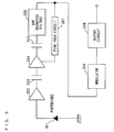
- Fig. 5 is an internal block diagram of a receiving sensor IC (integrated circuit) generally used as the receiver of the remote controlling equipment.
- the infrared signal transmitted from the transmitter of the remote controlling equipment is sensed by a photodiode 301 of the receiver and converted to an electrical signal.
- the electrical signal is amplified by an amplifier 302 and is supplied to an AGC (automatic gain control) amplifier 304 through a condenser 303 for removing a DC component.
- An output signal of the AGC amplifier 304 is supplied to a BPF (band-pass filter) 306 through a condenser 305 for removing a DC component.
- AGC automatic gain control
- the BPF 306 allows a component of a frequency band including the carrier frequency of the infrared signal to pass and attenuates other frequency components largely.
- An output signal of the BPF 306 is supplied to a gain control terminal of the AGC amplifier 304 via a peak hold circuit 307. By this, the level of the output signal of BPF 306 is adjusted to be constant.
- a demodulator 308 demodulates the output signal of the BPF 306 and outputs it via an output circuit 309.
- an intensity waveform of the infrared rays emitted from the fluorescent lamp is approximated as a sine curve.
- Fig. 6 is a chart showing a waveform of the drive voltages VD1, VD2, a waveform of the infrared radiation intensity of the first and the second light source groups 11, 12, and a waveform of the infrared radiation intensity of the backlight 101 when the phase difference ⁇ between the synchronous signal SY1 and the synchronous signal SY2 is 0° .
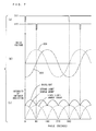
- Fig. 7 is a chart showing waveforms of the drive voltages VD1, VD2, waveforms of the infrared radiation intensity of the first and the second light source groups 11, 12, and a waveform of the infrared radiation intensity of the backlight 101 when the phase difference ⁇ between the synchronous signal SY1 and the synchronous signal SY2 is 90°.
- the waveform of the infrared radiation intensity of the backlight 101 is a synthesized intensity waveform of the infrared radiation intensity of the first light source group 11 and the infrared radiation intensity of the second light source group 12.
- phase difference ⁇ between the synchronous signal SY1 and the synchronous signal SY2 is 0° as shown in Fig. 6(a)
- a phase difference ⁇ between the drive voltage VD1 and the drive voltage VD2 is also 0 as shown in Fig. 6 (b) .
- a phase difference ⁇ between the infrared radiation intensity of the first light source group 11 and the infrared radiation intensity of the second light source group is also 0.
- the infrared radiation intensity of the first light source group 11 and the infrared radiation intensity of the second light source group 12 are synthesized so as to be intensified, an amplitude of the AC component of the waveform of infrared radiation intensity of the backlight 101 is increased.
- an increase in amplitude of the AC component lengthens time when the malfunction of the receiver continues.
- phase difference ⁇ between the synchronous signal SY1 and the synchronous signal SY2 is 90° as shown in Fig. 7(a)
- the phase difference ⁇ between the drive voltage VD1 and the drive voltage VD2 is also 90 ° as shown in Fig. 7(b).
- the phase difference ⁇ between the infrared radiation intensity of the first light source group 11 and the infrared radiation intensity of the second light source group is also 90°. Therefore, in the infrared radiation intensity of the backlight 101, although the DC component is superimposed on the AC component, the amplitude of the AC component is reduced to be small. Thus, it is considered that a reduction in the amplitude of the AC component shortens the time when the malfunction of the receiver continues.
- phase difference ⁇ is 180° and 360°, the same waveform of the infrared radiation intensity as in Fig. 6(c) appears and when the phase difference ⁇ is 270°, the same waveform of infrared radiation intensity as in Fig. 7 (c) appears.
- the phase difference ⁇ between the synchronous signal SY1 and the synchronous signal SY2 is set within a range of 60° to 120° or a range of 240° to 300°. This can makes the malfunction duration time te shorter than the malfunction duration time te when the first light source group 11 and the second light source group 12 light asynchronously.
- the phase difference ⁇ between the synchronous signal SY1 and the synchronous signal SY2 is set to a range of 75° to 105° or a range of 255° to 285°. This can make the malfunction duration time te sufficiently shorter. In addition, since the malfunction duration time comes in a start-up sequence of the display device with the backlight device, the display device, substantially, does not malfunction.
- phase difference ⁇ between the synchronous signal SY1 and the synchronous signal SY2 is set to 90° or 270°. This can makes the malfunction duration time te the shortest.
- the phase difference ⁇ between the synchronous signal SY1 and the synchronous signal SY2 can be set to the range of 60° to 120° or the range of 240° to 300°.
- the AC component in the waveform of the infrared radiation intensity of the backlight 101 can be reduced to be small. This can reduce the malfunction of the receiver.
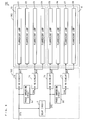
- Fig. 8 is a block diagram showing a configuration of a backlight device according to a second embodiment of the present invention.
- a backlight device 203 of Fig. 8 includes a drive unit 102 and a backlight 103.
- the drive unit 102 includes drive circuits 1a, 1b, 1c, 1d, the delay circuit 2, and phase inverting circuits 3a, 3b.
- the backlight 103 includes a first light source group 13 and a second light source group 14. Furthermore, the first light source group 13 includes fluorescent lamps 21 to 24 and the second light source group 14 includes fluorescent lamps 25 to 28.
- the backlight device 203 of Fig. 8 is provided on the back side of the liquid crystal panel 202 similar to the backlight device 201 of Fig. 2.
- the synchronous signal SY3 is supplied to the drive circuit 1a and the delay circuit 2 of Fig. 8.
- the drive circuit 1a supplies the AC drive voltage VD1 to the fluorescent lamps 21, 22 synchronously with the synchronous signal SY3. By this, the fluorescent lamps 21, 22 light up.
- the phase inverting circuit 3a supplies the drive circuit 1c a synchronous signal SY4 which is out of phase relative to the synchronous signal SY3 by 180°.
- the drive circuit 1c supplies an AC drive voltage VD3 to the fluorescent lamps 23, 24 synchronously with the synchronous signal SY4. By this, the fluorescent lamps 23, 24 light up.
- the delay circuit 2 delays the phase of the synchronous signal SY3 as set in advance and supplies the delayed synchronous signal SY5 to the drive circuit 1b.
- the drive circuit 1b supplies the AC drive voltage VD2 to the fluorescent lamps 25, 26 synchronously with the synchronous signal SY5. By this, the fluorescent lamps 25, 26 light up.
- the phase inverting circuit 3b supplies the drive circuit 1d a synchronous signal SY6 which is out of phase relative to the synchronous signal SY5 by 180°.
- the drive circuit 1d supplies an AC drive voltage VD4 to the fluorescent lamps 27, 28 synchronously with the synchronous signal SY6. By this, the fluorescent lamps 27, 28 light up.
- a phase difference between the synchronous signal SY3 and the synchronous signal SY5 is ⁇ .
- Fig. 9 is a chart showing waveforms of the drive voltages VD1, VD2, VD3, VD4, and a waveform of the infrared radiation intensity of the fluorescent lamps 21 to 24, a waveform of the infrared radiation intensity of the fluorescent lamps 25 to 28, waveforms of the infrared radiation intensity of the first and second light source groups 13, 14, and a waveform of the infrared radiation intensity of the backlight 103, when the phase difference ⁇ between the synchronous signal SY3 and the synchronous signal SY5 is 90°.
- the waveform of the infrared radiation intensity of the first light source group 13 is a synthesized intensity waveform of the infrared radiation intensity of the fluorescent lamps 21 to 24
- the waveform of the infrared radiation intensity of the second light source group 14 is a synthesized intensity waveform of the infrared radiation intensity of the fluorescent lamps 25 to 28
- the waveform of the infrared radiation intensity of the backlight 103 is a synthesized intensity waveform of the infrared radiation intensity of the first light source group 13 and the infrared radiation intensity of the second light source group 14.
- the drive voltage VD3 is in opposite phase to the drive voltage VD1. Further, the phase difference ⁇ between the drive voltage VD1 and the drive voltage VD2 becomes 90°, so that the drive voltage VD4 is in opposite phase to the drive voltage VD2.
- the fluorescent lamps 21, 22 and the fluorescent lamps 23, 24 light synchronously with, and in opposite phase to each other.
- the noise component caused from the respective fluorescent lamps in the first light source group 11 is cancelled.
- the fluorescent lamps 25, 26 and the fluorescent lamps 27, 28, light synchronously with, and in opposite phase to each other, so that the noise component caused from the respective fluorescent lamps is cancelled.
- the interference noise caused on the liquid crystal panel 202 can be reduced.
- the phase of the respective infrared radiation intensity of the fluorescent lamps 21 to 24 is identical, and the phase of the respective infrared radiation intensity of the fluorescent lamps 25 to 28 is also identical.
- the phase difference ⁇ between the infrared radiation intensity of the fluorescents lamps 21 to 24 and the infrared radiation intensity of the fluorescents lamps 25 to 28 is 90°
- the phase difference ⁇ between the infrared radiation intensity of the first light source group 13 and the infrared radiation intensity of the second light source group 14 is also 90 ° .
- the amplitude of the AC component is reduced to be small. This can shorten the time when the malfunction of the receiver continues.
- the relationship between the malfunction duration time te and the phase difference ⁇ also meets the relationship shown in Fig. 4. Furthermore, when the phase difference ⁇ is 270°, the same radiation intensity as in Fig. 9(c) appears.
- the phase difference ⁇ between the synchronous signal SY3 and the synchronous signal SY5 is set to a range of 60° to 120° or a range of 240° to 300°. This can makes the malfunction duration time te shorter than the malfunction duration time te when the first light source group 13 and the second light source group 14 light asynchronously.
- phase difference ⁇ between the synchronous signal SY3 and the synchronous signal SY5 is set to a range of 75° to 105° or a range of 255° to 285°. This can make the malfunction duration time te sufficiently shorter.
- phase difference ⁇ between the synchronous signal SY3 and the synchronous signal SY5 is set to 90° or 270°. This can makes the malfunction duration time te the shortest.
- the phase difference ⁇ between the synchronous signal SY3 and the synchronous signal SY5 within the range of 60° to 120° or the range of 240° to 300°, the AC component in the waveform of the infrared radiation intensity of the backlight 103 can be reduced to be small. This can reduce the malfunction of the receiver.
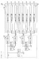
- Fig. 10 is a block diagram showing a configuration of a backlight device according to a third embodiment of the present invention.
- a backlight device 204 of Fig. 10 includes a drive unit 104 and a backlight 105.
- the drive unit 104 includes the drive circuits 1a, 1b, 1c, 1d, the delay circuit 2, and the phase inverting circuits 3a, 3b.
- the backlight 105 includes a first light source group 15 and a second light source group 16. Furthermore, the first light source group 15 includes the fluorescent lamps 21 to 24 and the second light source group 16 includes the fluorescent lamps 25 to 28.
- the backlight device 204 of Fig. 10 is different from the backlight device 203 of Fig. 8 in the following points.
- the first light source group 15 is divided into a plurality of first subgroups and the second light source group 16 is divided into a plurality of second subgroups.
- the plurality of first subgroups and the plurality of second subgroups are arranged alternately.
- the fluorescent lamps 21, 22 form one of the first subgroups and the fluorescent lamps 23, 24 form the other first subgroup.
- the fluorescent lamps 25, 26 form one of the second subgroups and the fluorescent lamps 27, 28 form the other second subgroup.
- the fluorescent lamps 25, 26 of the second light source group 16 are arranged next to the fluorescent lamps 21, 22 of the first light source group 15, the fluorescent lamps 23, 24 of the first light source group 15 are arranged next to the fluorescent lamps 25, 26 on opposite side of the fluorescent lamps 21, 22, and the fluorescent lamps 27, 28 of the second light source group 16 are arranged next to the fluorescent lamps 23, 24 on opposite side of the fluorescent lamps 25, 26.
- a waveform of the infrared radiation intensity of the backlight 105 is the same as the waveform of the infrared radiation intensity of the backlight 103 in the second embodiment, but since the first subgroups of the first light source group 15 and the second subgroups of the second light source group 16 are arranged alternately, infrared rays emitted from the first light source group 15 and infrared rays emitted from the second light source group 16 are synthesized at a short distance. By this, the effect described in Fig. 9 becomes more remarkable. As a result, the malfunction of the receiver of the remote controlling equipment can be further reduced.
- Fig. 11 is a block diagram showing a configuration of a backlight device according to a fourth embodiment of the present invention.
- a backlight device 205 of Fig. 11 includes the drive unit 102 and a backlight 106.
- the drive unit 102 includes the drive circuits 1a, 1b, 1c, 1d, the delay circuit 2, and the phase inverting circuits 3a, 3b.
- the backlight 106 includes a first light source group 17 and a second light source group 18. Furthermore, the first light source group 17 includes fluorescent lamps 31 to 33 and the second light source group 18 includes fluorescent lamps 34 to 38.
- the difference of the backlight device 205 of Fig. 11 from the backlight device 203 of Fig. 8 is that in the backlight 106, the first light source group 17 includes the fluorescent lamps 31 to 33 and the second light source group 18 includes the fluorescent lamps 34 to 38.
- the second light source group 18 includes more fluorescent lamps than the first light source group 17.
- the direct backlight device is described, the above-described configurations may be applied to an edge type backlight device.
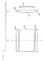
- Fig. 12 (a) is a schematic plane view of a liquid crystal display device using an edge type backlight device with straight tube lamps and Fig. 12(b) is a cross-section view taken along A-A line in Fig. 12(a).
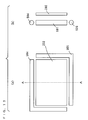
- Fig. 13(a) is a schematic plane view of a liquid crystal display device using an edge type backlight device with L-shaped lamps
- Fig. 13 (b) is a cross-section view taken along A-A line in Fig. 13(a).
- the liquid crystal display device of Fig. 12 includes the liquid crystal panel 202, a light guide plate 501, and straight tube lamps 502, 503.
- the straight tube lamp 502 is provided on one side of the light guide plate 501 and the straight tube lamp 503 is provided on the other side of the light guide plate 501.
- the liquid crystal display device of Fig. 13 includes the liquid crystal panel 202, the light guide plate 501 and L-shaped lamps 504, 505.
- the L-shaped lamp 504 is provided so as to cover one side in a long edge direction of the light guide plate 501 and one side in a short edge direction thereof and the L-shaped lamp 505 is provided so as to cover the other side in the long edge direction of the light guide plate 501 and the other side in the short edge direction thereof.
- liquid crystal display device of Figs. 12 and 13 light generated by the straight tube lamps 502, 503 and the L-shaped lamps 504, 505 enters the light guide plate 501.
- the light entering the light guide plate 501 is caused to reflect so as to irradiate the whole liquid crystal panel 202 uniformly by reflecting dots (not shown) or reflecting grooves (not shown), which are provided in the light guide plate 501.
- the display of the liquid crystal panel 202 is performed.
- the straight tube lamp 502 and the L-shaped lamp 504 are driven by the drive circuit 1a of Fig. 1, and the straight tube lamp 503 and the L-shaped lamp 505 are driven by the drive circuit 1b of Fig. 1.
- phase shifter that shifts the phase using another analog circuit such as a PLL (Phase Locked Loop) circuit and a filter circuit may be configured.
- PLL Phase Locked Loop
- the synchronous signal SY1 and the synchronous signal SY3 each correspond to a first synchronous signal
- the synchronous signal SY2 and the synchronous signal SY5 each correspond to a second synchronous signal
- the synchronous signal SY4 corresponds to a third synchronous signal
- the synchronous signal SY6 corresponds to a fourth synchronous signal.
- the drive voltage VD1 corresponds to a first drive voltage
- the drive voltage VD2 corresponds to a second drive voltage
- the drive voltage VD3 corresponds to a third drive voltage
- the drive voltage VD4 corresponds to a fourth drive voltage
- the drive circuit 1a corresponds to a first drive circuit
- the drive circuit 1b corresponds to a second drive circuit
- the drive circuit 1c corresponds to a third drive circuit
- the drive circuit 1d corresponds to a fourth drive circuit.
- the delay circuit 2 corresponds to a first signal generating circuit
- the phase inverting circuit 3a corresponds to a second signal generating circuit
- the phase inverting circuit 3b corresponds to a third signal generating circuit.
Landscapes
- Liquid Crystal Display Device Control (AREA)
- Circuit Arrangement For Electric Light Sources In General (AREA)
- Control Of Indicators Other Than Cathode Ray Tubes (AREA)
- Circuit Arrangements For Discharge Lamps (AREA)
- Liquid Crystal (AREA)
Applications Claiming Priority (2)
| Application Number | Priority Date | Filing Date | Title |
|---|---|---|---|
| JP2003321387 | 2003-09-12 | ||
| PCT/JP2004/013476 WO2005027590A1 (fr) | 2003-09-12 | 2004-09-09 | Dispositif de retroeclairage et unite d'affichage le comprenant |
Publications (2)
| Publication Number | Publication Date |
|---|---|
| EP1667496A1 true EP1667496A1 (fr) | 2006-06-07 |
| EP1667496A4 EP1667496A4 (fr) | 2010-03-31 |
Family
ID=34308634
Family Applications (1)
| Application Number | Title | Priority Date | Filing Date |
|---|---|---|---|
| EP04773135A Withdrawn EP1667496A4 (fr) | 2003-09-12 | 2004-09-09 | Dispositif de retroeclairage et unite d'affichage le comprenant |
Country Status (8)
| Country | Link |
|---|---|
| US (1) | US7449838B2 (fr) |
| EP (1) | EP1667496A4 (fr) |
| JP (1) | JPWO2005027590A1 (fr) |
| KR (1) | KR100708518B1 (fr) |
| CN (1) | CN1849848A (fr) |
| CA (1) | CA2538498A1 (fr) |
| TW (1) | TW200528819A (fr) |
| WO (1) | WO2005027590A1 (fr) |
Families Citing this family (15)
| Publication number | Priority date | Publication date | Assignee | Title |
|---|---|---|---|---|
| TWI251803B (en) * | 2004-09-10 | 2006-03-21 | Ind Tech Res Inst | Method for modulating and driving backlight sources for flat panel displays |
| US7956838B2 (en) * | 2005-01-25 | 2011-06-07 | Sharp Kabushiki Kaisha | Display device, instrument panel, automatic vehicle, and method of driving display device |
| CN100365476C (zh) * | 2006-02-16 | 2008-01-30 | 友达光电股份有限公司 | 液晶显示器及其驱动方法 |
| TW200737093A (en) * | 2006-03-31 | 2007-10-01 | Coretronic Corp | Backlight device and controlling method thereof |
| TWI287677B (en) * | 2006-05-12 | 2007-10-01 | Chi Mei Optoelectronics Corp | Structure and method of quasi-U lamp for improving current uniformity of the backlight module |
| KR101373400B1 (ko) * | 2006-12-27 | 2014-03-14 | 엘지디스플레이 주식회사 | 액정표시장치 및 그의 구동방법 |
| CN101682977B (zh) * | 2007-06-26 | 2012-10-31 | 夏普株式会社 | 背光源控制装置及具备该背光源控制装置的显示装置 |
| TWI392926B (zh) * | 2009-01-16 | 2013-04-11 | Au Optronics Corp | 背光模組 |
| KR101580921B1 (ko) * | 2009-08-14 | 2015-12-30 | 삼성디스플레이 주식회사 | 표시 장치 |
| JP2011145395A (ja) * | 2010-01-13 | 2011-07-28 | Sony Corp | 液晶表示装置 |
| US8648550B2 (en) * | 2010-03-13 | 2014-02-11 | Zilog, Inc. | Ambient light sensor auto-calibration in a lighting control system |
| CN101923841B (zh) * | 2010-08-17 | 2012-05-30 | 深圳市华星光电技术有限公司 | 背光模块以及液晶显示器 |
| TW201303447A (zh) * | 2011-07-11 | 2013-01-16 | Beyond Innovation Tech Co Ltd | 背光模組與使用其之液晶顯示器 |
| WO2015141273A1 (fr) * | 2014-03-20 | 2015-09-24 | 富士フイルム株式会社 | Dispositif d'affichage et son procédé de commande, et dispositif de viseur |
| KR102485821B1 (ko) * | 2016-03-28 | 2023-01-09 | 삼성디스플레이 주식회사 | 표시 장치 |
Family Cites Families (8)
| Publication number | Priority date | Publication date | Assignee | Title |
|---|---|---|---|---|
| JPH06151064A (ja) * | 1991-10-29 | 1994-05-31 | Toshiba Lighting & Technol Corp | 室内照明装置および室内照明方法 |
| TWI226478B (en) * | 1998-07-31 | 2005-01-11 | Toshiba Corp | Flat panel display device |
| JP3293592B2 (ja) | 1999-06-11 | 2002-06-17 | 日本電気株式会社 | 液晶表示装置とそのバックライトの点灯方法 |
| JP3270435B2 (ja) | 1999-10-04 | 2002-04-02 | 松下電器産業株式会社 | 表示装置およびその輝度制御方法 |
| CN1220098C (zh) * | 2000-04-28 | 2005-09-21 | 夏普株式会社 | 显示器件、显示器件驱动方法和装有显示器件的电子设备 |
| KR100759362B1 (ko) * | 2001-01-18 | 2007-09-19 | 삼성전자주식회사 | 백라이트 어셈블리 및 이를 갖는 액정 표시 장치 |
| JP2002352994A (ja) * | 2001-05-28 | 2002-12-06 | Matsushita Electric Works Ltd | 放電灯点灯装置および照明器具 |
| US20050140634A1 (en) * | 2003-12-26 | 2005-06-30 | Nec Corporation | Liquid crystal display device, and method and circuit for driving liquid crystal display device |
-
2004
- 2004-09-09 CN CNA2004800262901A patent/CN1849848A/zh active Pending
- 2004-09-09 WO PCT/JP2004/013476 patent/WO2005027590A1/fr not_active Ceased
- 2004-09-09 JP JP2005513951A patent/JPWO2005027590A1/ja active Pending
- 2004-09-09 KR KR1020067005043A patent/KR100708518B1/ko not_active Expired - Fee Related
- 2004-09-09 CA CA002538498A patent/CA2538498A1/fr not_active Abandoned
- 2004-09-09 US US10/571,059 patent/US7449838B2/en not_active Expired - Fee Related
- 2004-09-09 EP EP04773135A patent/EP1667496A4/fr not_active Withdrawn
- 2004-09-10 TW TW093127502A patent/TW200528819A/zh unknown
Also Published As
| Publication number | Publication date |
|---|---|
| EP1667496A4 (fr) | 2010-03-31 |
| US7449838B2 (en) | 2008-11-11 |
| CN1849848A (zh) | 2006-10-18 |
| KR100708518B1 (ko) | 2007-04-16 |
| WO2005027590A1 (fr) | 2005-03-24 |
| TW200528819A (en) | 2005-09-01 |
| KR20060064671A (ko) | 2006-06-13 |
| JPWO2005027590A1 (ja) | 2006-11-24 |
| US20070024570A1 (en) | 2007-02-01 |
| CA2538498A1 (fr) | 2005-03-24 |
Similar Documents
| Publication | Publication Date | Title |
|---|---|---|
| EP1667496A1 (fr) | Dispositif de retroeclairage et unite d'affichage le comprenant | |
| US6680588B2 (en) | Low noise backlight system for use in display device and method for driving the same | |
| US8497853B2 (en) | Flat panel display device, controller, and method for displaying images | |
| US9041747B2 (en) | Display control apparatus | |
| WO2004055577A1 (fr) | Afficheur à cristaux liquides | |
| US8289268B2 (en) | Apparatus and method for improving video quality of display device | |
| US20150310809A1 (en) | Backlight device and control method thereof | |
| US20040217715A1 (en) | Switch frequency adjusting system and method for burst mode of liquid crystal display | |
| US20060098935A1 (en) | Pulse width modulation inverter circuit and control method thereof | |
| US8248360B2 (en) | Backlight control device and display apparatus including the same | |
| KR20090022653A (ko) | 디스플레이 장치 및 휘도 제어 방법 | |
| KR100674256B1 (ko) | 디밍 제어 방법 및 이를 이용하는 조명 시스템 | |
| JP2007094266A (ja) | 表示装置用の放電管点灯装置 | |
| EP2175699A1 (fr) | Ballast électronique de lampe à décharge | |
| US7791284B2 (en) | Cold cathode tube drive device | |
| TW200621946A (en) | Light emitting device with a Eu(III)-activated phosphor and second phosphor | |
| JP2011139324A (ja) | Amラジオ放送におけるビート妨害回避方法、装置及びプログラム | |
| EP1249854A3 (fr) | Panneau d'affichage à plasma | |
| KR20050013821A (ko) | 쵸핑 주파수 조정 가능한 액정 디스플레이 장치 및 그조정 방법 | |
| KR100726665B1 (ko) | 플라즈마 디스플레이 장치 | |
| JPH1126183A (ja) | 液晶ディスプレイ用調光装置 | |
| JP2004274389A (ja) | 表示装置 | |
| JPH11260585A (ja) | 照明装置 | |
| KR200196294Y1 (ko) | 엘시디 모니터에 적용된 백라이트 램프의 수명 연장을 위한 장치 | |
| JP2004259510A (ja) | 放電ランプ点灯装置及びこれを用いた液晶表示装置 |
Legal Events
| Date | Code | Title | Description |
|---|---|---|---|
| PUAI | Public reference made under article 153(3) epc to a published international application that has entered the european phase |
Free format text: ORIGINAL CODE: 0009012 |
|
| 17P | Request for examination filed |
Effective date: 20060309 |
|
| AK | Designated contracting states |
Kind code of ref document: A1 Designated state(s): AT BE BG CH CY CZ DE DK EE ES FI FR GB GR HU IE IT LI LU MC NL PL PT RO SE SI SK TR |
|
| DAX | Request for extension of the european patent (deleted) | ||
| RAP1 | Party data changed (applicant data changed or rights of an application transferred) |
Owner name: PANASONIC CORPORATION |
|
| A4 | Supplementary search report drawn up and despatched |
Effective date: 20100225 |
|
| 17Q | First examination report despatched |
Effective date: 20100823 |
|
| STAA | Information on the status of an ep patent application or granted ep patent |
Free format text: STATUS: THE APPLICATION IS DEEMED TO BE WITHDRAWN |
|
| 18D | Application deemed to be withdrawn |
Effective date: 20110106 |