EP1667500B1 - Vorrichtung und Verfahren zur Herstellung, Sortierung und Integration von Materialien mittels holographischer optischer Fallen - Google Patents
Vorrichtung und Verfahren zur Herstellung, Sortierung und Integration von Materialien mittels holographischer optischer Fallen Download PDFInfo
- Publication number
- EP1667500B1 EP1667500B1 EP05028231A EP05028231A EP1667500B1 EP 1667500 B1 EP1667500 B1 EP 1667500B1 EP 05028231 A EP05028231 A EP 05028231A EP 05028231 A EP05028231 A EP 05028231A EP 1667500 B1 EP1667500 B1 EP 1667500B1
- Authority
- EP
- European Patent Office
- Prior art keywords
- optical
- traps
- particles
- trap
- absorbing
- Prior art date
- Legal status (The legal status is an assumption and is not a legal conclusion. Google has not performed a legal analysis and makes no representation as to the accuracy of the status listed.)
- Expired - Lifetime
Links
- 230000003287 optical effect Effects 0.000 title claims abstract description 180
- 238000000034 method Methods 0.000 title claims abstract description 65
- 239000000463 material Substances 0.000 title abstract description 22
- 239000002245 particle Substances 0.000 claims abstract description 53
- 210000004027 cell Anatomy 0.000 claims description 29
- 210000003743 erythrocyte Anatomy 0.000 claims description 10
- 210000004369 blood Anatomy 0.000 claims description 6
- 239000008280 blood Substances 0.000 claims description 6
- 238000010438 heat treatment Methods 0.000 claims description 3
- 230000003068 static effect Effects 0.000 claims description 3
- 238000012360 testing method Methods 0.000 claims description 3
- 230000031700 light absorption Effects 0.000 claims description 2
- 230000008855 peristalsis Effects 0.000 claims description 2
- 230000036962 time dependent Effects 0.000 claims description 2
- 230000003993 interaction Effects 0.000 abstract description 6
- 230000001131 transforming effect Effects 0.000 abstract description 3
- 230000008901 benefit Effects 0.000 description 9
- 238000010521 absorption reaction Methods 0.000 description 8
- 206010028980 Neoplasm Diseases 0.000 description 7
- 230000006378 damage Effects 0.000 description 6
- 238000000926 separation method Methods 0.000 description 6
- 238000003491 array Methods 0.000 description 5
- 238000001514 detection method Methods 0.000 description 5
- 239000012530 fluid Substances 0.000 description 5
- 238000003384 imaging method Methods 0.000 description 5
- 201000011510 cancer Diseases 0.000 description 4
- 238000006073 displacement reaction Methods 0.000 description 4
- 239000012634 fragment Substances 0.000 description 4
- 238000000651 laser trapping Methods 0.000 description 4
- 239000002502 liposome Substances 0.000 description 4
- 230000000694 effects Effects 0.000 description 3
- 238000004519 manufacturing process Methods 0.000 description 3
- 238000012546 transfer Methods 0.000 description 3
- 238000013519 translation Methods 0.000 description 3
- VYPSYNLAJGMNEJ-UHFFFAOYSA-N Silicium dioxide Chemical compound O=[Si]=O VYPSYNLAJGMNEJ-UHFFFAOYSA-N 0.000 description 2
- 238000004458 analytical method Methods 0.000 description 2
- 210000000170 cell membrane Anatomy 0.000 description 2
- 238000005119 centrifugation Methods 0.000 description 2
- 238000005520 cutting process Methods 0.000 description 2
- 238000005538 encapsulation Methods 0.000 description 2
- 238000005286 illumination Methods 0.000 description 2
- 239000004973 liquid crystal related substance Substances 0.000 description 2
- 238000012986 modification Methods 0.000 description 2
- 230000004048 modification Effects 0.000 description 2
- 108090000623 proteins and genes Proteins 0.000 description 2
- 230000005855 radiation Effects 0.000 description 2
- 230000009466 transformation Effects 0.000 description 2
- 238000000844 transformation Methods 0.000 description 2
- 230000002159 abnormal effect Effects 0.000 description 1
- 239000011358 absorbing material Substances 0.000 description 1
- 230000004075 alteration Effects 0.000 description 1
- 238000013459 approach Methods 0.000 description 1
- 238000000149 argon plasma sintering Methods 0.000 description 1
- 210000004507 artificial chromosome Anatomy 0.000 description 1
- 239000012620 biological material Substances 0.000 description 1
- 210000003850 cellular structure Anatomy 0.000 description 1
- 230000009956 central mechanism Effects 0.000 description 1
- 230000008859 change Effects 0.000 description 1
- 238000007796 conventional method Methods 0.000 description 1
- 238000002425 crystallisation Methods 0.000 description 1
- 230000008025 crystallization Effects 0.000 description 1
- 238000013500 data storage Methods 0.000 description 1
- 238000003745 diagnosis Methods 0.000 description 1
- 238000010586 diagram Methods 0.000 description 1
- 238000009792 diffusion process Methods 0.000 description 1
- 238000004520 electroporation Methods 0.000 description 1
- 238000005516 engineering process Methods 0.000 description 1
- 238000000684 flow cytometry Methods 0.000 description 1
- 238000011010 flushing procedure Methods 0.000 description 1
- 230000001939 inductive effect Effects 0.000 description 1
- 210000000265 leukocyte Anatomy 0.000 description 1
- 230000007246 mechanism Effects 0.000 description 1
- 230000001404 mediated effect Effects 0.000 description 1
- 239000012528 membrane Substances 0.000 description 1
- 230000034217 membrane fusion Effects 0.000 description 1
- 230000002503 metabolic effect Effects 0.000 description 1
- 239000007769 metal material Substances 0.000 description 1
- 239000000203 mixture Substances 0.000 description 1
- 239000002114 nanocomposite Substances 0.000 description 1
- 230000005693 optoelectronics Effects 0.000 description 1
- 230000003534 oscillatory effect Effects 0.000 description 1
- 239000011236 particulate material Substances 0.000 description 1
- 238000007781 pre-processing Methods 0.000 description 1
- 230000008569 process Effects 0.000 description 1
- 238000012545 processing Methods 0.000 description 1
- 102000004169 proteins and genes Human genes 0.000 description 1
- 210000001747 pupil Anatomy 0.000 description 1
- 238000012216 screening Methods 0.000 description 1
- 238000005204 segregation Methods 0.000 description 1
- 238000001338 self-assembly Methods 0.000 description 1
- 230000035945 sensitivity Effects 0.000 description 1
- 239000000377 silicon dioxide Substances 0.000 description 1
- 239000007779 soft material Substances 0.000 description 1
- 239000000126 substance Substances 0.000 description 1
- 239000000758 substrate Substances 0.000 description 1
- 239000013603 viral vector Substances 0.000 description 1
- 239000002699 waste material Substances 0.000 description 1
- XLYOFNOQVPJJNP-UHFFFAOYSA-N water Substances O XLYOFNOQVPJJNP-UHFFFAOYSA-N 0.000 description 1
Images


Classifications
-
- C—CHEMISTRY; METALLURGY
- C12—BIOCHEMISTRY; BEER; SPIRITS; WINE; VINEGAR; MICROBIOLOGY; ENZYMOLOGY; MUTATION OR GENETIC ENGINEERING
- C12N—MICROORGANISMS OR ENZYMES; COMPOSITIONS THEREOF; PROPAGATING, PRESERVING, OR MAINTAINING MICROORGANISMS; MUTATION OR GENETIC ENGINEERING; CULTURE MEDIA
- C12N13/00—Treatment of microorganisms or enzymes with electrical or wave energy, e.g. magnetism, sonic waves
-
- C—CHEMISTRY; METALLURGY
- C12—BIOCHEMISTRY; BEER; SPIRITS; WINE; VINEGAR; MICROBIOLOGY; ENZYMOLOGY; MUTATION OR GENETIC ENGINEERING
- C12N—MICROORGANISMS OR ENZYMES; COMPOSITIONS THEREOF; PROPAGATING, PRESERVING, OR MAINTAINING MICROORGANISMS; MUTATION OR GENETIC ENGINEERING; CULTURE MEDIA
- C12N15/00—Mutation or genetic engineering; DNA or RNA concerning genetic engineering, vectors, e.g. plasmids, or their isolation, preparation or purification; Use of hosts therefor
- C12N15/09—Recombinant DNA-technology
- C12N15/87—Introduction of foreign genetic material using processes not otherwise provided for, e.g. co-transformation
- C12N15/88—Introduction of foreign genetic material using processes not otherwise provided for, e.g. co-transformation using microencapsulation, e.g. using amphiphile liposome vesicle
-
- C—CHEMISTRY; METALLURGY
- C12—BIOCHEMISTRY; BEER; SPIRITS; WINE; VINEGAR; MICROBIOLOGY; ENZYMOLOGY; MUTATION OR GENETIC ENGINEERING
- C12M—APPARATUS FOR ENZYMOLOGY OR MICROBIOLOGY; APPARATUS FOR CULTURING MICROORGANISMS FOR PRODUCING BIOMASS, FOR GROWING CELLS OR FOR OBTAINING FERMENTATION OR METABOLIC PRODUCTS, i.e. BIOREACTORS OR FERMENTERS
- C12M35/00—Means for application of stress for stimulating the growth of microorganisms or the generation of fermentation or metabolic products; Means for electroporation or cell fusion
- C12M35/02—Electrical or electromagnetic means, e.g. for electroporation or for cell fusion
-
- C—CHEMISTRY; METALLURGY
- C12—BIOCHEMISTRY; BEER; SPIRITS; WINE; VINEGAR; MICROBIOLOGY; ENZYMOLOGY; MUTATION OR GENETIC ENGINEERING
- C12N—MICROORGANISMS OR ENZYMES; COMPOSITIONS THEREOF; PROPAGATING, PRESERVING, OR MAINTAINING MICROORGANISMS; MUTATION OR GENETIC ENGINEERING; CULTURE MEDIA
- C12N15/00—Mutation or genetic engineering; DNA or RNA concerning genetic engineering, vectors, e.g. plasmids, or their isolation, preparation or purification; Use of hosts therefor
- C12N15/09—Recombinant DNA-technology
- C12N15/87—Introduction of foreign genetic material using processes not otherwise provided for, e.g. co-transformation
-
- G—PHYSICS
- G02—OPTICS
- G02B—OPTICAL ELEMENTS, SYSTEMS OR APPARATUS
- G02B21/00—Microscopes
- G02B21/32—Micromanipulators structurally combined with microscopes
-
- G—PHYSICS
- G02—OPTICS
- G02B—OPTICAL ELEMENTS, SYSTEMS OR APPARATUS
- G02B27/00—Optical systems or apparatus not provided for by any of the groups G02B1/00 - G02B26/00, G02B30/00
- G02B27/10—Beam splitting or combining systems
-
- G—PHYSICS
- G02—OPTICS
- G02B—OPTICAL ELEMENTS, SYSTEMS OR APPARATUS
- G02B5/00—Optical elements other than lenses
- G02B5/32—Holograms used as optical elements
-
- H—ELECTRICITY
- H05—ELECTRIC TECHNIQUES NOT OTHERWISE PROVIDED FOR
- H05H—PLASMA TECHNIQUE; PRODUCTION OF ACCELERATED ELECTRICALLY-CHARGED PARTICLES OR OF NEUTRONS; PRODUCTION OR ACCELERATION OF NEUTRAL MOLECULAR OR ATOMIC BEAMS
- H05H3/00—Production or acceleration of neutral particle beams, e.g. molecular or atomic beams
- H05H3/04—Acceleration by electromagnetic wave pressure
Definitions
- the present invention is related generally to a method and apparatus for manipulating and modifying small dielectric particles or other materials using the intense illumination and intensity gradients in strongly focused beams of light.
- the invention is related to a method and apparatus which uses focused laser light directed by a diffractive optical element, such as a hologram or diffraction grating, to create optical traps or traps and any one of a variety of selectable optical intensity patters to assemble or direct particulate materials, or other affected materials, into a desired spatial pattern for any one of a myriad of uses.
- a diffractive optical element such as a hologram or diffraction grating
- the invention is related to methods for manipulating, effecting interaction of photochemically transforming and/or sorting small dielectric particles or other materials.
- optical trap i.e., trap
- optical gradient forces from a single beam of light to manipulate the position of a small dielectric particle immersed in a fluid medium whose refractive index is smaller than that of the particle.
- the optical trap technique has been generalized to enable manipulation of reflecting, absorbing and low dielectric constant particles as well.
- U.S. Patent No. 6,055,106 issued April 25, 2000 discloses the manipulation of multiple particles with multiple traps.
- Optical traps originally described by A. Ashkin et al., have become an established method for trapping, moving and otherwise manipulating mesoscopic volumes of matter. See A. Ashkin et al., "Observation of single-beam gradient forces optical trap for dielectric particles, "Optics Letters 11, 288-290 (1986) . Central to their operation is minimizing the absorption of trapping light to avoid damaging the trapped material.
- Optical scalpels operate on the opposite principle, using the energy in a tightly focused laser beam to cut through soft materials. This application discloses and claims a novel hybrid system in which focused beams of laser light operate as optical traps for some nonabsorbing particles in a heterogeneous sample and simultaneously as optical scalpels for others.
- optical trap technology involves introducing foreign materials into living cells by breaching the cell membrane without causing it to fail entirely, and for moving the materials through the breach.
- Various methods for accomplishing this have been developed, including viral vectors for transfecting short lengths of DNA, the gene gun and its variants for transferring larger sections, and electroporation for inducing transmembrane diffusion. None appears to be appropriate for transferring physically large materials, particular if those materials are themselves fragile.
- a novel method and apparatus for using a laser beam input to a diffractive optical element to generate a three-dimensional arrangement of optical traps is also provided.
- a time-dependent addressable phase-shifting medium such as a liquid crystal phase shifting array or other phase medium
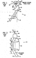
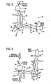
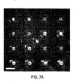
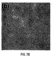
- FIGS. 1 and 2 illustrate several prior art methods and systems. These systems will first be reviewed, and then the methods of the present invention will be described in terms of the optical trap embodiment examples of FIGS. 3-7A and 7B .
- optical gradient forces arise from use of a single beam of light 12 to controllably manipulate a small dielectric particle 14 dispersed in a medium 16 whose index of refraction is smaller than that of the particle 14.
- the nature of the optical gradient forces is well known, and also it is well understood that the principle has been generalized to allow manipulation of reflecting, absorbing and low dielectric constant particles as well.
- the optical trap system 10 is applied by using a light beam 12 (such as a laser beam) capable of applying the necessary forces needed to carry out the optical trapping effect needed to manipulate a particle.
- a light beam 12 such as a laser beam
- the method used to create a conventional form of the optical trap 10 is to project one or more beams of light, each with a specified degree of collimation, through the center of a back aperture 24 of a converging optical element (such as an objective lens 20).
- the light beam 12 has width of "w" and having an input angle, ⁇ , relative to an optical axis 22.
- the light beam 12 is input to a back aperture 24 of the objective lens 20 and output from a front aperture 26 substantially converging to a focal point 28 n a focal plane 30 of imaging volume 32 with the focal point 28 coinciding with an optical trap 33.
- any beam of light brought to a diffraction-limited focus, and possessing sufficiently large axial intensity gradients to trap a particle stably against axial radiation pressure can form the basis for the optical trap system 10.
- the minimum numerical aperture to form a trap is about 0.9 to about 1.0.
- the light beam 12 being a collimated laser beam and having its axis coincident with the optical axis 22, the light beam 12 enters the back aperture 24 of the objective lens 20 and is brought to a focus in the imaging volume 32 at the center point c of the objective lens focal plane 30.
- the axis of the light beam 12 is displaced by the angle ⁇ with respect to the optical axis 22, beam axis 31 and the optical axis 22 coincide at the center point B of the back aperture 12.
- This displacement enables translation of the optical trap across the field of view by an amount that depends on the angular modification of the objective lens 20.
- the two variables, angular displacement ⁇ and varying convergence of the light beam 12 can be used to form the optical trap at selected positions within the imaging volume 32.
- a multiple number of the optical traps 33 can be arranged in different locations provided that multiple beams of light 12 are applied to the back aperture 24 at the different angles ⁇ and with differing degrees of collimation.
- optical gradient forces exerted on the particle to be trapped must exceed other radiation pressures arising from light scattering and absorption. In general this necessitates the wave front of the light beam 12 to have an appropriate shape at the back aperture 24.
- the beam diameter, w should substantially coincide with the diameter of the entrance pupil 24.
- beam profiles such as Laguerre-Gaussian modes
- the optical trap system 10 can translate the optical trap 33 across the field of view of the objective lens 20.
- a telescope 34 is constructed of lenses L1 and L2 which establishes a point A which is optically conjugate to the center point B in the prior art system FIG. 1 .
- the light beam 12 passing through the point A also passes through the point B and thus meets the basic requirements for performing as the optical trap system 10.
- the degree of collimation is preserved by positioning the lenses L1 and L2 as shown in FIG. 2 , their focal lengths and other optical characteristics being selected to optimize the transfer of properties of the telescope 34.
- magnification of the telescope 34 can be chosen to optimize angular displacement of the light beam 12 and its width w in the plane of the back aperture 24 of the objective lens 20.
- several of the light beams 12 can be used to form several associated optical traps.
- Such multiple beams 12 can be created from multiple independent input beams or from a single beam manipulated by conventional reflective and/or refractive optical elements.
- a diffractive optical element 40 is disposed substantially in a plane 42 conjugate to back aperture 24 of the objective lens 20. Note that only a single diffracted output beam 44 is shown for clarity, but it should be understood that a plurality of such beams 44 can be created by the diffractive optical element 40.
- the input light beam 12 incident on the diffractive optical element 40 is split into a pattern of the output beam 44 characteristic of the nature of the diffractive optical element 40, each of which emanates from the point A.
- the output beams 44 also pass through point B as a consequence of the downstream optical elements described hereinbefore.
- the diffractive optical element 40 of FIG. 3 is shown as being normal to the input light beam 12, but many other arrangements are possible.
- the light beam 12 arrives at an oblique angle ⁇ relative to the optic axis 22 and not at a normal to the diffractive optical element 40.
- the diffracted beams 44 emanating from point A will from optical traps 50 on focal plane 52 of the imaging volume 32 (seen best in FIG. 1 ).
- an undiffractive portion 54 of the input light beam 12 can be removed from the optical trap system 10. This configuration thus enables processing less background light and improves efficiency and effectiveness of forming optical traps.
- the diffractive optical element 40 can include computer generated holograms which split the input light beam 12 into a preselected desired pattern. Combining such holograms with the remainder of the optical elements in FIGS. 3 and 4 enables creation of arbitrary arrays in which the diffractive optical element 40 is used to shape the wavefront of each diffracted beam independently. Therefore, the optical traps 50 can be disposed not only in the focal plane 52 of the objective lens 20, but also out of the focal plane 52 to form a three-dimensional arrangement of the optical traps 50.
- a focusing optical element such as the objective lens 20 (or other like functionally equivalent optical device, such as a Fresnel lens) to converge the diffracted beam 44 to form the optical traps 50.
- the telescope 34 or other equivalent transfer optics, creates a point A conjugate to the center point B of the previous back aperture 24.
- the diffractive optical element 40 is placed in a plane containing point A.
- arbitrary arrays of the optical traps 50 can be created without use of the telescope 34.
- the diffractive optical element 40 can be placed directly in the plane containing point B.
- one of the lenses can be positioned in the hologram itself rather than in the telescope 34.
- either static or time dependant diffractive optical elements 40 can be used.
- a dynamic, or time dependant version one can create time changing arrays of the optical traps 50 which can be part of a system utilizing such a feature.
- these dynamic optical elements 40 can be used to actively move particles and other materials with diverse optical properties relative to one another.
- the diffractive optical element 40 can be a liquid crystal spatial light modulator encoding computer-generated phase modulations onto the wavefront of an incident laser beam.
- a spatial light modulator may also be used in conjunction with a phase ring in place of the diffractive optical element.
- a system can be constructed to carry out continous translation of the optical trap 50.
- a gimbal mounted mirror 60 is placed with its center of rotation at point A.
- the light beam 12 is incident on the surface of the mirror 60 and has its axis passing through point A and will be projected to the back aperture 24. Tilting of the mirror 60 causes a change of the angle of incidence of the light beam 12 relative to the mirror 60, and this feature can be used to translate the resulting optical trap 50.
- a second telescope 62 is formed from lenses L3 and L4 which creates a point A' which is conjugate to point A.
- the diffractive optical element 40 placed at point A' now creates a pattern of diffracted beams 64, each of which passes through point A to form one of the trap 50 in an array of the optical traps system 10.
- the mirror 60 translates the entire trap array as a unit. This methodology is useful for precisely aligning the optical trap array with stationary substrate, for dynamically stiffening the optical trap 50 through small-amplitude rapid oscillatory displacements, as well as for any application requiring a general translation capability.
- the array of the optical traps 50 also can be translated vertically relative to the sample stage by moving the sample stage or by adjusting the telescope 34.
- the optical trap array can also be translated laterally relative to the sample by moving the sample stage.
- This feature would be particularly useful for movement beyond the range of the objective lens' field of view.
- the optical system is arranged to permit viewing images of particles trapped by the optical traps 10.
- a dichroic beamsplitter 70 or other equivalent optical beamsplitter, is inserted between the objective lens 20 and the optical train of the optical trap system 10.
- the beamsplitter 70 selectively reflects the wavelength of light used to form the optical trap array and transmits other wavelengths.
- the light beam 12 used to form the optical traps 50 is transmitted to the back aperture 24 with high efficiency while light beach 66 used to form images can pass through to imaging optics.
- the method includes the steps of encapsulating the material to be transferred in, for example, a liposome, fusing the liposome to the cell membrane, and puncturing the juncture to effect transfer.
- the first step takes advantage of any of a variety of known possible encapsulation techniques. Once encapsulation is complete, the liposome can be captured with optical traps and translated toward a target cell. Depending on the material's sensitivity to light, several separate optical traps might be preferable to one, in which case holographic optical traps offer advantages to other techniques, such as scanned optical traps.
- holographic optical traps illuminate each of their traps continuously.
- a scanned optical trap For a scanned optical trap to achieve the same trapping force as a continuously illuminated trap, it must provide at least the same time-averaged intensity. This means that the scanned trap has to have a higher peak intensity by a factor proportional to at least the number of trapping regions. This higher peak intensity increases the opportunities for optically-induced damage in the trapped material. This damage can arise from at least three mechanisms: (1) single-photon absorption leading to local heating, (2) single-photon absorption leading to photochemical transformations, and (3) multiple-photon absorption leading to photochemical transformations.
- Events (1) and (2) can be mitigated by choosing a wavelength of light which is weakly absorbed by the trapping material and by the surrounding fluid medium.
- Event (3) is a more general problem and is mitigated in part by working with longer-wavelength light.
- Multiple-photon absorption the central mechanism of the photopolymerization part of this technique, occurs at a rate proportional to the intensity raised to a power (i.e., I 2 for two-photon absorption). The rates for such processes are rapidly reduced to acceptable levels by reducing the peak intensity of the trapping beam. As a result, lower intensity, continuously-illuminated holographic optical traps are preferable to time-shared scanned traps.
- holographic optical trap method lends itself to distributing more independent traps throughout the volume of an extended object than does any scanned trap technique.
- holographic optical traps can distribute traps across an objects three-dimensional contours, unlike scanned traps which are limited to a single plane.
- Distributing the trapping force among multiple sites on an object further permits holographic optical traps to minimize the maximum intensity and maximum force applied to any one point of the object. This may be thought of as being analogous to a bed of nails, in which any one could cause damage, bur distributing the loading among multiple nails reduces the local force below the threshold for damage.
- holographic optical traps offer substantial benefits over both scanned traps and individual conventional optical traps. If the cell itself is motile, it also may be held in place and oriented with holographic optical traps. For some applications, for example when material must be transferred to a particular part of a cell while bypassing others, optical trap manipulation offers advantages. A single set of holographic optical traps can be use to hold both the cell and the liposome simultanenously.
- an optical trap or trap array 300 can be advantageously formed from focused beams of laser light which operate as optical traps for some nonabsorbing particles 310 in a sample and as optical scalpels for others. Rather than precisely cutting the absorbing particles 290 as traditionally done by an optical scalpel, however, absorption of light is used to obliterate the absorbing particles 290 nonspecifically so as to reduce them to very small pieces 330. These small pieces then can be separated from the undamaged nonabsorbing particles left behind in optical traps 320.
- An example of the utility of this method is the problem of searching for cancerous cells in a sample of blood.
- the vast number of red blood cells in the sample would have to be separated from the candidate cancer cells before testing can begin.
- Light from optical traps operating in the visible range of wavelengths, for example at a wavelength of 532 nm would be absorbed strongly by red blood cells and consequently can be used to destroy them through local heating.
- Other unpigmented cells can be trapped by the same visible traps and manipulated for further testing.
- an array of visible optical traps arranged with their characteristic spacing considerably smaller than the size of a red blood cell. A mixture of cells driven through this array of optical traps by an externally mediated fluid flow would encounter these optical traps.
- the strongly-absorbing cells would be reduced to much smaller components, such as membrane fragments through their interaction with the light. These smaller components would have a comparatively weaker interaction with the light and a small portion might be trapped by some of the traps in the array. More likely, however, they would be washed away by the fluid flow. Rather than being damaged by the light, weakly absorbing cells would encounter one or more optical traps in the array and experience and trapping force.
- the intact cells would have larger and more numerous regions susceptible to optical trapping than the fragments of the destroyed cells, and therefore would be preferentially trapped by the array of optical traps.
- Cells localized in the array of optical traps can be transported for collection by moving the optical traps themselves, for example taking advantage of the features of an earlier application of the assignee herein, (Grier et al., U.S. Patent Application Serial No. 09/875,812 ; U.S. Patent Application Publication US 2002-0185592 A1, published December 12, 2002 ) by moving the sample container to transport the trapped cells to a collection region within the sample container, or by periodically turning off the traps and directing cells through a flow of fluid to a collection area. In any of these ways, the cells which do not absorb light are collected separately from the cells that do.
- This approach can be generalized from sorting cells to sorting any other material whose absorption coefficients differ substantially for at least one particular wavelength of light.
- the benefits of this manipulation include excellent fidelity for rejecting the undesired absorbing material, and the ability to perform other active sorting steps. The same benefits would accrue to other applications of this ablative particle sorting method.
- separation of nonabsorbing particles can be effected with multiple optical traps created with the holographic optical trap technique. Separation of the trapped particles for the obliterated absorbing particles could be performed with the previously disclosed techniques of active trap manipulation, optical peristalsis, or passive lateral defection in a flow. The separation could also be performed in a microfluidics device with one channel for flushing waste products from the obliteration of absorbing particles and other channels for collecting selected nonabsorbing particles.
- the goal is to select a wavelength which is absorbed strongly by the unwanted subpopulation of a mixed sample, and very weakly by the other subpopulation to be retrieved. Retrieval of the weakly absorbing subpopulation proceed through conventional methods, and the separation in this case being effected through the passive destruction of the unwanted fraction, rather than through active selection. This could also be a preprocessing step for other analytical methods such as flow cytometry.
- this method could be used for early detection of cancer through blood screening.
- several kinds of cancers in their earliest stages do not form particularly well defined tumors but, instead, define regions of abnormal cells which tend to slough onto the bloodstream.
- detection of those cells would provide an indication that the patient has an early stage cancer.
- Such detection would provide at least a tentative diagnosis long before other methods requiring detection of a complete tumor or its metabolic products.
- this method would provide for early and more effective treatment. This can be compared with conventional separations methods for centrifugation to separate the denser, haemoglobin-bearing red blood cells from other cells carried in the blood.
- centrifugation often entrains the lighter cells with the heavier ones, thus making detection very difficult.
- blood samples can be made to flow through an array of optical traps having wavelength and intensity that will destroy the cellular structure of the red blood cells, leaving non-red blood cells, such as white blood cells and possible cancer cells, intact.
- non-red blood cells such as white blood cells and possible cancer cells
- the red blood cells will be reduced to fragments too small to trap.
- the undamaged cells can be trapped by the optical traps and transported, for example, by sequentially updating the pattern of traps, to a collection point for subsequent analysis.
Landscapes
- Health & Medical Sciences (AREA)
- Genetics & Genomics (AREA)
- Engineering & Computer Science (AREA)
- Life Sciences & Earth Sciences (AREA)
- Physics & Mathematics (AREA)
- Chemical & Material Sciences (AREA)
- Bioinformatics & Cheminformatics (AREA)
- Wood Science & Technology (AREA)
- Organic Chemistry (AREA)
- Zoology (AREA)
- Biotechnology (AREA)
- Biomedical Technology (AREA)
- General Engineering & Computer Science (AREA)
- Microbiology (AREA)
- General Health & Medical Sciences (AREA)
- Biochemistry (AREA)
- Optics & Photonics (AREA)
- General Physics & Mathematics (AREA)
- Plant Pathology (AREA)
- Molecular Biology (AREA)
- Biophysics (AREA)
- Analytical Chemistry (AREA)
- Electromagnetism (AREA)
- Spectroscopy & Molecular Physics (AREA)
- Cell Biology (AREA)
- Sustainable Development (AREA)
- Plasma & Fusion (AREA)
- Physical Or Chemical Processes And Apparatus (AREA)
- Apparatus Associated With Microorganisms And Enzymes (AREA)
- Holo Graphy (AREA)
- Microscoopes, Condenser (AREA)
- Investigating Or Analysing Materials By Optical Means (AREA)
- Investigating Or Analysing Biological Materials (AREA)
- Powder Metallurgy (AREA)
- Diffracting Gratings Or Hologram Optical Elements (AREA)
- Micro-Organisms Or Cultivation Processes Thereof (AREA)
Claims (13)
- Verfahren zum Sortieren nicht absorbierender Teilchen aus absorbierenden Teilchen unter Verwendung einer oder mehrerer optischer Falle/n, wobei das Verfahren umfasst:Bereitstellen eines optischen Beugungselements, um einen Laserstrahl zu empfangen und mehrere separate Laserstrahlen zu bilden;Bereitstellen eines Fokussierelements, und zwar dem optischen Beugungselement nachgeordnet, wobei das optische Beugungselement mit dem Fokussierelement zusammenwirkt, um die Laserstrahlen zur Ausbildung eines im Wesentlichen fokussierten Punkts jeweils separat zu konvergieren, um eine separate optische Falle im fokussierten Punkt für jedes der Teilchen unter Verwendung eines der separaten Laserstrahlen für jedes Teilchen zu bilden;Durchlaufenlassen absorbierender Teilchen und nicht absorbierender Teilchen durch die optische Falle, wodurch Lichtabsorption die absorbierenden Teilchen unspezifisch zerstört, um sie in kleinere Stücke zu zerkleinern;Trennen der kleinen Stücke von den unbeschädigten nicht absorbierenden Teilchen, die in den optischen Fallen zurückbleiben; undEntfernen der nicht absorbierenden Teilchen aus den optischen Fallen.
- Verfahren nach Anspruch 1, wobei entweder statische oder zeitabhängige optische Beugungselemente (40) verwendet werden.
- Verfahren nach Anspruch 1 oder 2, wobei ein optisches Beugungselement (40) in Form eines Raumlichtmodulators verwendet wird, der computergenerierte Phasenmodulationen auf die Wellenfront eines einfallenden Laserstrahls codiert.
- Verfahren nach einem der Ansprüche 1 bis 3, wobei das optische System angeordnet ist, um eine Sichtbarmachung von Bildern von durch die optischen Fallen eingefangenen Teilchen zu ermöglichen.
- Verfahren nach einem der Ansprüche 1 bis 4, wobei ein dichroitischer Strahlenteiler (70) oder ein anderer äquivalenter optischer Strahlenteiler zwischen die Objektivlinse (20) und die optische Strecke des optischen Fallensystems (10) eingesetzt ist.
- Verfahren nach einem der Ansprüche 1 bis 5, wobei für die optischen Fallen eine Wellenlänge ausgewählt wird, die durch eine ungewollte Teilpopulation einer Mischprobe stark absorbiert wird.
- Verfahren nach einem der Ansprüche 1 bis 6, wobei für die optischen Fallen eine Wellenlänge ausgewählt wird, die durch eine zu gewinnende Teilpopulation nur sehr schwach absorbiert wird.
- Verfahren nach einem der Ansprüche 1 bis 7, wobei das Gewinnen der schwach absorbierenden Teilpopulation dadurch erfolgt, dass das Muster der Fallen sequentiell aktualisiert wird, und dass die schwach absorbierende Teilpopulation zu einem Sammelpunkt transportiert wird.
- Verfahren nach einem der Ansprüche 1 bis 8, wobei das Verfahren eingesetzt wird, um Krebszellen in einer Blutprobe zu suchen.
- Verfahren nach einem der Ansprüche 1 bis 9, wobei Licht im sichtbaren Bereich von Wellenlängen, zum Beispiel mit einer Wellenlänge von 532 nm verwendet wird, das durch rote Blutzellen stark absorbiert wird, und in der Folge dazu verwendet werden kann, sie durch lokales Erhitzen zu zerstören.
- Verfahren nach Anspruch 10, wobei unpigmentierte Zellen mit denselben sichtbaren Fallen eingefangen und für weiteres Testen manipuliert werden können.
- Verfahren nach einem der Ansprüche 1 bis 11, wobei das Aussortieren durch optische Peristaltik, passive seitliche Ablenkung in einer Strömung und/oder eine mikroströmungstechnische Vorrichtung erfolgt, wobei ein Kanal die absorbierenden Teilchen ausspült, und die anderen Kanäle ausgewählte nicht absorbierende Teilchen sammeln.
- Verfahren nach Anspruch 9, wobei rote Blutzellen im Blut durch Ablation abgetragen werden, und nicht rote Blutzellen nicht beschädigt und eingefangen werden.
Applications Claiming Priority (2)
| Application Number | Priority Date | Filing Date | Title |
|---|---|---|---|
| US10/210,519 US6863406B2 (en) | 2002-08-01 | 2002-08-01 | Apparatus and method for fabricating, sorting, and integrating materials with holographic optical traps |
| EP03755730A EP1532849B1 (de) | 2002-08-01 | 2003-07-31 | Vorrichtung und verfahren zur herstellung, sortierung und integration von materialien mittels holographischeroptischer fallen |
Related Parent Applications (1)
| Application Number | Title | Priority Date | Filing Date |
|---|---|---|---|
| EP03755730A Division EP1532849B1 (de) | 2002-08-01 | 2003-07-31 | Vorrichtung und verfahren zur herstellung, sortierung und integration von materialien mittels holographischeroptischer fallen |
Publications (2)
| Publication Number | Publication Date |
|---|---|
| EP1667500A1 EP1667500A1 (de) | 2006-06-07 |
| EP1667500B1 true EP1667500B1 (de) | 2008-02-13 |
Family
ID=31187356
Family Applications (4)
| Application Number | Title | Priority Date | Filing Date |
|---|---|---|---|
| EP03755730A Expired - Lifetime EP1532849B1 (de) | 2002-08-01 | 2003-07-31 | Vorrichtung und verfahren zur herstellung, sortierung und integration von materialien mittels holographischeroptischer fallen |
| EP05028230A Expired - Lifetime EP1684312B1 (de) | 2002-08-01 | 2003-07-31 | Vorrichtung und Verfahren zur Herstellung von Materialien mit holographischen optischen Fallen. |
| EP05028231A Expired - Lifetime EP1667500B1 (de) | 2002-08-01 | 2003-07-31 | Vorrichtung und Verfahren zur Herstellung, Sortierung und Integration von Materialien mittels holographischer optischer Fallen |
| EP07108976A Withdrawn EP1821585A1 (de) | 2002-08-01 | 2003-07-31 | Vorrichtung und Verfahren zur Herstellung, Sortierung und Integration von Materialien mit holographischen optischen Fallen |
Family Applications Before (2)
| Application Number | Title | Priority Date | Filing Date |
|---|---|---|---|
| EP03755730A Expired - Lifetime EP1532849B1 (de) | 2002-08-01 | 2003-07-31 | Vorrichtung und verfahren zur herstellung, sortierung und integration von materialien mittels holographischeroptischer fallen |
| EP05028230A Expired - Lifetime EP1684312B1 (de) | 2002-08-01 | 2003-07-31 | Vorrichtung und Verfahren zur Herstellung von Materialien mit holographischen optischen Fallen. |
Family Applications After (1)
| Application Number | Title | Priority Date | Filing Date |
|---|---|---|---|
| EP07108976A Withdrawn EP1821585A1 (de) | 2002-08-01 | 2003-07-31 | Vorrichtung und Verfahren zur Herstellung, Sortierung und Integration von Materialien mit holographischen optischen Fallen |
Country Status (14)
| Country | Link |
|---|---|
| US (3) | US6863406B2 (de) |
| EP (4) | EP1532849B1 (de) |
| JP (1) | JP2005534321A (de) |
| KR (1) | KR20050062522A (de) |
| CN (2) | CN1326430C (de) |
| AT (3) | ATE433187T1 (de) |
| AU (1) | AU2003273224A1 (de) |
| BR (1) | BR0313170A (de) |
| CA (1) | CA2494362A1 (de) |
| DE (3) | DE60319161T2 (de) |
| IL (1) | IL166578A0 (de) |
| RU (1) | RU2005105586A (de) |
| TW (1) | TWI279787B (de) |
| WO (1) | WO2004014112A2 (de) |
Families Citing this family (37)
| Publication number | Priority date | Publication date | Assignee | Title |
|---|---|---|---|---|
| US6055106A (en) * | 1998-02-03 | 2000-04-25 | Arch Development Corporation | Apparatus for applying optical gradient forces |
| CA2524646C (en) * | 2003-05-08 | 2012-02-21 | The University Court Of The University Of St Andrews | Fractionation of particles |
| CA2525843A1 (en) * | 2003-05-16 | 2004-12-02 | University Of Chicago | Optical fractionation methods and apparatus |
| US7442339B2 (en) * | 2004-03-31 | 2008-10-28 | Intel Corporation | Microfluidic apparatus, Raman spectroscopy systems, and methods for performing molecular reactions |
| WO2006012352A2 (en) * | 2004-06-28 | 2006-02-02 | Haemonetics Corporation | Blood component separation system with stationary separation chamber |
| US20060177940A1 (en) * | 2005-02-07 | 2006-08-10 | Furst Eric M | Optical trap separations in microfluidic flows |
| WO2007038259A2 (en) * | 2005-09-23 | 2007-04-05 | Massachusetts Institute Of Technology | Optical trapping with a semiconductor |
| US7948632B2 (en) * | 2005-12-22 | 2011-05-24 | Phase Holographic Imaging Phi Ab | Method and apparatus for analysis of a sample of cells |
| GB0618606D0 (en) * | 2006-09-21 | 2006-11-01 | Univ St Andrews | Optical sorting |
| GB0618605D0 (en) * | 2006-09-21 | 2006-11-01 | Univ St Andrews | Optical sorting |
| EP2492921A1 (de) * | 2007-01-26 | 2012-08-29 | New York University | Holografische Mikroskopie von holografisch gefangenen dreidimensionalen Strukturen |
| US7883207B2 (en) | 2007-12-14 | 2011-02-08 | Pixeloptics, Inc. | Refractive-diffractive multifocal lens |
| US8139944B2 (en) * | 2007-05-08 | 2012-03-20 | The Boeing Company | Method and apparatus for clearing an optical channel |
| WO2009002537A1 (en) * | 2007-06-25 | 2008-12-31 | Tufts University | Optical array device and methods of use thereof for screening, analysis and manipulation of particles |
| CN101795744A (zh) * | 2007-09-11 | 2010-08-04 | 阿尔利克斯公司 | 用于分选物体的结合方法和仪器 |
| WO2009035621A1 (en) * | 2007-09-13 | 2009-03-19 | Arryx, Inc. | Methods and apparatuses for sorting objects in forensic dna analysis and medical diagnostics |
| WO2009079342A1 (en) * | 2007-12-14 | 2009-06-25 | Pixeloptics Inc. | Refractive-diffractive multifocal lens |
| CN101407807B (zh) * | 2008-11-19 | 2013-11-06 | 暨南大学 | 对染色体进行处理而改变细胞遗传特性的方法及其应用 |
| DE102008060332B4 (de) * | 2008-12-03 | 2013-01-10 | Albert-Ludwigs-Universität Freiburg | Verfahren zum Sortieren von mindestens einem Partikel mit einer mikrofluidischen Sortiervorrichtung mit optischer Pinzette |
| CN102365543A (zh) | 2009-01-16 | 2012-02-29 | 纽约大学 | 用全息视频显微术的自动实时粒子表征和三维速度计量 |
| DE102009029831A1 (de) * | 2009-06-17 | 2011-01-13 | W.O.M. World Of Medicine Ag | Vorrichtung und Verfahren für die Mehr-Photonen-Fluoreszenzmikroskopie zur Gewinnung von Informationen aus biologischem Gewebe |
| EP2452221B1 (de) * | 2009-07-09 | 2020-01-01 | Howard Hughes Medical Institute | Mikroskopie mit adaptiver optik |
| WO2011079139A2 (en) * | 2009-12-22 | 2011-06-30 | New York University | Sorting colloidal particles into multiple channels with optical forces: prismatic optical fractionation |
| DE102010027720A1 (de) * | 2010-04-14 | 2011-10-20 | Carl Zeiss Microlmaging Gmbh | Verfahren und Vorrichtungen zur Positions- und Kraftdetektion |
| JP6195830B2 (ja) * | 2011-07-14 | 2017-09-13 | ホワルド フグヘス メドイクアル インストイトウテ | 適応光学系を有する顕微鏡検査法 |
| CN103612390B (zh) * | 2013-11-12 | 2016-03-09 | 广东卓耐普智能股份有限公司 | 一种3d激光打印机及其打印方法 |
| US9315846B2 (en) * | 2014-02-13 | 2016-04-19 | The United States Of America As Represented By Secretary Of The Navy | Fluidic channel based on a filtered, free-space electromagnetic wave source |
| EP3218690B1 (de) | 2014-11-12 | 2022-03-09 | New York University | Kolloidale fingerabdrücke für weiche materialien unter verwendung von totaler holografischer charakterisierung |
| US9249385B1 (en) * | 2014-12-18 | 2016-02-02 | City University Of Hong Kong | System and method for fusing cells |
| DK3414517T3 (da) | 2016-02-08 | 2021-12-13 | Univ New York | Holografisk karakterisering af proteinaggregater |
| CN110370627B (zh) * | 2019-08-08 | 2021-09-28 | 中国科学院广州生物医药与健康研究院 | 一种3d光固化的方法和3d光固化设备 |
| US11543338B2 (en) | 2019-10-25 | 2023-01-03 | New York University | Holographic characterization of irregular particles |
| US11948302B2 (en) | 2020-03-09 | 2024-04-02 | New York University | Automated holographic video microscopy assay |
| EP4256369A4 (de) * | 2020-10-25 | 2025-01-08 | David Cohen | Atmosphärenpenetrierender laser |
| CN112880912B (zh) * | 2021-01-08 | 2022-01-18 | 浙江大学 | 基于真空全息光镊的空间分辨压强测量系统及方法 |
| DE102021212505A1 (de) | 2021-11-08 | 2023-05-11 | Robert Bosch Gesellschaft mit beschränkter Haftung | Optische Vorrichtung zum Anregen einer Probe, Analysegerät und Verfahren zum Anregen einer Probe |
| WO2025106610A1 (en) * | 2023-11-15 | 2025-05-22 | Purdue Research Foundation | Systems and methods for spatiotemporal precise optical manipulation of biological activities |
Family Cites Families (11)
| Publication number | Priority date | Publication date | Assignee | Title |
|---|---|---|---|---|
| JPH0797167B2 (ja) * | 1987-01-14 | 1995-10-18 | 住友電気工業株式会社 | 光バンドルフアイバの端末構造 |
| EP0451681B1 (de) * | 1990-04-05 | 1997-11-05 | Seiko Epson Corporation | Optische Vorrichtung |
| US5079169A (en) | 1990-05-22 | 1992-01-07 | The Regents Of The Stanford Leland Junior University | Method for optically manipulating polymer filaments |
| EP0682671A4 (de) * | 1993-02-01 | 1998-01-14 | Seq Ltd | Verfahren und geräte zur sequenzierung von dns. |
| US5739879A (en) * | 1995-11-13 | 1998-04-14 | Industrial Technology Research Institute | Backlighting device for liquid crystal displays |
| US5912106A (en) * | 1996-09-10 | 1999-06-15 | Ciba Specialty Chemicals Corporation | Method for improving photoimage quality |
| JP3727950B2 (ja) * | 1996-09-10 | 2005-12-21 | オーリクス ビオファーマソティカル エス.アー. | 多成分流体を供給するアプリケータ装置 |
| US6055106A (en) | 1998-02-03 | 2000-04-25 | Arch Development Corporation | Apparatus for applying optical gradient forces |
| JP2002325572A (ja) * | 2000-12-25 | 2002-11-12 | Univ Osaka | 外来物質の導入方法 |
| US6416190B1 (en) * | 2001-04-27 | 2002-07-09 | University Of Chicago | Apparatus for using optical tweezers to manipulate materials |
| EP1421365A1 (de) * | 2001-07-19 | 2004-05-26 | Tufts University | Optische array-vorrichtung sowie verfahren zur verwendung davon für das screening , die analyse und die manipulation von partikeln |
-
2002
- 2002-08-01 US US10/210,519 patent/US6863406B2/en not_active Expired - Fee Related
-
2003
- 2003-07-31 WO PCT/US2003/023991 patent/WO2004014112A2/en not_active Ceased
- 2003-07-31 DE DE60319161T patent/DE60319161T2/de not_active Expired - Lifetime
- 2003-07-31 EP EP03755730A patent/EP1532849B1/de not_active Expired - Lifetime
- 2003-07-31 DE DE60327903T patent/DE60327903D1/de not_active Expired - Lifetime
- 2003-07-31 AU AU2003273224A patent/AU2003273224A1/en not_active Abandoned
- 2003-07-31 KR KR1020057001893A patent/KR20050062522A/ko not_active Withdrawn
- 2003-07-31 RU RU2005105586/13A patent/RU2005105586A/ru not_active Application Discontinuation
- 2003-07-31 CN CNB038235102A patent/CN1326430C/zh not_active Expired - Fee Related
- 2003-07-31 AT AT05028230T patent/ATE433187T1/de not_active IP Right Cessation
- 2003-07-31 EP EP05028230A patent/EP1684312B1/de not_active Expired - Lifetime
- 2003-07-31 AT AT03755730T patent/ATE373408T1/de not_active IP Right Cessation
- 2003-07-31 JP JP2004526276A patent/JP2005534321A/ja active Pending
- 2003-07-31 BR BRPI0313170-0A patent/BR0313170A/pt not_active IP Right Cessation
- 2003-07-31 EP EP05028231A patent/EP1667500B1/de not_active Expired - Lifetime
- 2003-07-31 CA CA002494362A patent/CA2494362A1/en not_active Abandoned
- 2003-07-31 DE DE60316303T patent/DE60316303T2/de not_active Expired - Fee Related
- 2003-07-31 CN CNA2007101096552A patent/CN101114054A/zh active Pending
- 2003-07-31 EP EP07108976A patent/EP1821585A1/de not_active Withdrawn
- 2003-07-31 AT AT05028231T patent/ATE386418T1/de not_active IP Right Cessation
- 2003-08-15 TW TW092122546A patent/TWI279787B/zh not_active IP Right Cessation
-
2005
- 2005-01-06 US US11/029,396 patent/US7588940B2/en not_active Expired - Fee Related
- 2005-01-30 IL IL16657805A patent/IL166578A0/xx unknown
-
2009
- 2009-04-01 US US12/385,202 patent/US8128242B2/en not_active Expired - Fee Related
Also Published As
Similar Documents
| Publication | Publication Date | Title |
|---|---|---|
| EP1532849B1 (de) | Vorrichtung und verfahren zur herstellung, sortierung und integration von materialien mittels holographischeroptischer fallen | |
| EP1053492B1 (de) | Vorrichtung zur erzeugung optischer gradientenkräfte | |
| US5939716A (en) | Three-dimensional light trap for reflective particles | |
| EP2270816B1 (de) | System und Verfahren zum Sortieren von Materialien mithilfe einer holografischen Lasersteuerung | |
| EP1325540B1 (de) | Vorrichtung zur anwendung optischer gradientenkräfte | |
| AU2002243203A1 (en) | Apparatus for applying optical gradient forces | |
| HK1092643B (en) | Apparatus and method for fabricating, sorting, and integrating materials with holographic optical traps | |
| HK1113053A (en) | Apparatus and method for fabricating, sorting, and integrating materials with holographic optical traps | |
| HK1094276B (en) | Apparatus and method for fabricating materials with holographic optical traps | |
| HK1033855B (en) | Apparatus for applying optical gradient forces |
Legal Events
| Date | Code | Title | Description |
|---|---|---|---|
| PUAI | Public reference made under article 153(3) epc to a published international application that has entered the european phase |
Free format text: ORIGINAL CODE: 0009012 |
|
| 17P | Request for examination filed |
Effective date: 20051222 |
|
| AC | Divisional application: reference to earlier application |
Ref document number: 1532849 Country of ref document: EP Kind code of ref document: P |
|
| AK | Designated contracting states |
Kind code of ref document: A1 Designated state(s): AT BE BG CH CY CZ DE DK EE ES FI FR GB GR HU IE IT LI LU MC NL PT RO SE SI SK TR |
|
| 17Q | First examination report despatched |
Effective date: 20061222 |
|
| REG | Reference to a national code |
Ref country code: HK Ref legal event code: DE Ref document number: 1092643 Country of ref document: HK |
|
| AKX | Designation fees paid |
Designated state(s): AT BE BG CH CY CZ DE DK EE ES FI FR GB GR HU IE IT LI LU MC NL PT RO SE SI SK TR |
|
| 17Q | First examination report despatched |
Effective date: 20061222 |
|
| GRAP | Despatch of communication of intention to grant a patent |
Free format text: ORIGINAL CODE: EPIDOSNIGR1 |
|
| GRAS | Grant fee paid |
Free format text: ORIGINAL CODE: EPIDOSNIGR3 |
|
| GRAA | (expected) grant |
Free format text: ORIGINAL CODE: 0009210 |
|
| AC | Divisional application: reference to earlier application |
Ref document number: 1532849 Country of ref document: EP Kind code of ref document: P |
|
| AK | Designated contracting states |
Kind code of ref document: B1 Designated state(s): AT BE BG CH CY CZ DE DK EE ES FI FR GB GR HU IE IT LI LU MC NL PT RO SE SI SK TR |
|
| REG | Reference to a national code |
Ref country code: GB Ref legal event code: FG4D |
|
| REG | Reference to a national code |
Ref country code: CH Ref legal event code: EP |
|
| REG | Reference to a national code |
Ref country code: IE Ref legal event code: FG4D |
|
| REF | Corresponds to: |
Ref document number: 60319161 Country of ref document: DE Date of ref document: 20080327 Kind code of ref document: P |
|
| REG | Reference to a national code |
Ref country code: HK Ref legal event code: GR Ref document number: 1092643 Country of ref document: HK |
|
| PG25 | Lapsed in a contracting state [announced via postgrant information from national office to epo] |
Ref country code: FI Free format text: LAPSE BECAUSE OF FAILURE TO SUBMIT A TRANSLATION OF THE DESCRIPTION OR TO PAY THE FEE WITHIN THE PRESCRIBED TIME-LIMIT Effective date: 20080213 Ref country code: ES Free format text: LAPSE BECAUSE OF FAILURE TO SUBMIT A TRANSLATION OF THE DESCRIPTION OR TO PAY THE FEE WITHIN THE PRESCRIBED TIME-LIMIT Effective date: 20080524 |
|
| NLV1 | Nl: lapsed or annulled due to failure to fulfill the requirements of art. 29p and 29m of the patents act | ||
| PG25 | Lapsed in a contracting state [announced via postgrant information from national office to epo] |
Ref country code: AT Free format text: LAPSE BECAUSE OF FAILURE TO SUBMIT A TRANSLATION OF THE DESCRIPTION OR TO PAY THE FEE WITHIN THE PRESCRIBED TIME-LIMIT Effective date: 20080213 |
|
| PG25 | Lapsed in a contracting state [announced via postgrant information from national office to epo] |
Ref country code: SI Free format text: LAPSE BECAUSE OF FAILURE TO SUBMIT A TRANSLATION OF THE DESCRIPTION OR TO PAY THE FEE WITHIN THE PRESCRIBED TIME-LIMIT Effective date: 20080213 Ref country code: BE Free format text: LAPSE BECAUSE OF FAILURE TO SUBMIT A TRANSLATION OF THE DESCRIPTION OR TO PAY THE FEE WITHIN THE PRESCRIBED TIME-LIMIT Effective date: 20080213 |
|
| ET | Fr: translation filed | ||
| PG25 | Lapsed in a contracting state [announced via postgrant information from national office to epo] |
Ref country code: CZ Free format text: LAPSE BECAUSE OF FAILURE TO SUBMIT A TRANSLATION OF THE DESCRIPTION OR TO PAY THE FEE WITHIN THE PRESCRIBED TIME-LIMIT Effective date: 20080213 Ref country code: SE Free format text: LAPSE BECAUSE OF FAILURE TO SUBMIT A TRANSLATION OF THE DESCRIPTION OR TO PAY THE FEE WITHIN THE PRESCRIBED TIME-LIMIT Effective date: 20080513 Ref country code: SK Free format text: LAPSE BECAUSE OF FAILURE TO SUBMIT A TRANSLATION OF THE DESCRIPTION OR TO PAY THE FEE WITHIN THE PRESCRIBED TIME-LIMIT Effective date: 20080213 Ref country code: NL Free format text: LAPSE BECAUSE OF FAILURE TO SUBMIT A TRANSLATION OF THE DESCRIPTION OR TO PAY THE FEE WITHIN THE PRESCRIBED TIME-LIMIT Effective date: 20080213 Ref country code: DK Free format text: LAPSE BECAUSE OF FAILURE TO SUBMIT A TRANSLATION OF THE DESCRIPTION OR TO PAY THE FEE WITHIN THE PRESCRIBED TIME-LIMIT Effective date: 20080213 Ref country code: PT Free format text: LAPSE BECAUSE OF FAILURE TO SUBMIT A TRANSLATION OF THE DESCRIPTION OR TO PAY THE FEE WITHIN THE PRESCRIBED TIME-LIMIT Effective date: 20080714 |
|
| PG25 | Lapsed in a contracting state [announced via postgrant information from national office to epo] |
Ref country code: RO Free format text: LAPSE BECAUSE OF FAILURE TO SUBMIT A TRANSLATION OF THE DESCRIPTION OR TO PAY THE FEE WITHIN THE PRESCRIBED TIME-LIMIT Effective date: 20080213 |
|
| PLBE | No opposition filed within time limit |
Free format text: ORIGINAL CODE: 0009261 |
|
| STAA | Information on the status of an ep patent application or granted ep patent |
Free format text: STATUS: NO OPPOSITION FILED WITHIN TIME LIMIT |
|
| 26N | No opposition filed |
Effective date: 20081114 |
|
| REG | Reference to a national code |
Ref country code: CH Ref legal event code: PL |
|
| PG25 | Lapsed in a contracting state [announced via postgrant information from national office to epo] |
Ref country code: MC Free format text: LAPSE BECAUSE OF NON-PAYMENT OF DUE FEES Effective date: 20080731 |
|
| PG25 | Lapsed in a contracting state [announced via postgrant information from national office to epo] |
Ref country code: EE Free format text: LAPSE BECAUSE OF FAILURE TO SUBMIT A TRANSLATION OF THE DESCRIPTION OR TO PAY THE FEE WITHIN THE PRESCRIBED TIME-LIMIT Effective date: 20080213 Ref country code: BG Free format text: LAPSE BECAUSE OF FAILURE TO SUBMIT A TRANSLATION OF THE DESCRIPTION OR TO PAY THE FEE WITHIN THE PRESCRIBED TIME-LIMIT Effective date: 20080513 |
|
| PG25 | Lapsed in a contracting state [announced via postgrant information from national office to epo] |
Ref country code: CH Free format text: LAPSE BECAUSE OF NON-PAYMENT OF DUE FEES Effective date: 20080731 Ref country code: LI Free format text: LAPSE BECAUSE OF NON-PAYMENT OF DUE FEES Effective date: 20080731 |
|
| PG25 | Lapsed in a contracting state [announced via postgrant information from national office to epo] |
Ref country code: IE Free format text: LAPSE BECAUSE OF NON-PAYMENT OF DUE FEES Effective date: 20080731 Ref country code: CY Free format text: LAPSE BECAUSE OF FAILURE TO SUBMIT A TRANSLATION OF THE DESCRIPTION OR TO PAY THE FEE WITHIN THE PRESCRIBED TIME-LIMIT Effective date: 20080213 |
|
| PGFP | Annual fee paid to national office [announced via postgrant information from national office to epo] |
Ref country code: FR Payment date: 20090717 Year of fee payment: 7 |
|
| PGFP | Annual fee paid to national office [announced via postgrant information from national office to epo] |
Ref country code: IT Payment date: 20090727 Year of fee payment: 7 |
|
| PG25 | Lapsed in a contracting state [announced via postgrant information from national office to epo] |
Ref country code: HU Free format text: LAPSE BECAUSE OF FAILURE TO SUBMIT A TRANSLATION OF THE DESCRIPTION OR TO PAY THE FEE WITHIN THE PRESCRIBED TIME-LIMIT Effective date: 20080814 Ref country code: LU Free format text: LAPSE BECAUSE OF NON-PAYMENT OF DUE FEES Effective date: 20080731 |
|
| PG25 | Lapsed in a contracting state [announced via postgrant information from national office to epo] |
Ref country code: TR Free format text: LAPSE BECAUSE OF FAILURE TO SUBMIT A TRANSLATION OF THE DESCRIPTION OR TO PAY THE FEE WITHIN THE PRESCRIBED TIME-LIMIT Effective date: 20080213 |
|
| PG25 | Lapsed in a contracting state [announced via postgrant information from national office to epo] |
Ref country code: GR Free format text: LAPSE BECAUSE OF FAILURE TO SUBMIT A TRANSLATION OF THE DESCRIPTION OR TO PAY THE FEE WITHIN THE PRESCRIBED TIME-LIMIT Effective date: 20080514 |
|
| REG | Reference to a national code |
Ref country code: FR Ref legal event code: ST Effective date: 20110331 |
|
| PG25 | Lapsed in a contracting state [announced via postgrant information from national office to epo] |
Ref country code: FR Free format text: LAPSE BECAUSE OF NON-PAYMENT OF DUE FEES Effective date: 20100802 Ref country code: IT Free format text: LAPSE BECAUSE OF NON-PAYMENT OF DUE FEES Effective date: 20100731 |
|
| PGFP | Annual fee paid to national office [announced via postgrant information from national office to epo] |
Ref country code: GB Payment date: 20110729 Year of fee payment: 9 |
|
| PGFP | Annual fee paid to national office [announced via postgrant information from national office to epo] |
Ref country code: DE Payment date: 20120725 Year of fee payment: 10 |
|
| GBPC | Gb: european patent ceased through non-payment of renewal fee |
Effective date: 20120731 |
|
| PG25 | Lapsed in a contracting state [announced via postgrant information from national office to epo] |
Ref country code: GB Free format text: LAPSE BECAUSE OF NON-PAYMENT OF DUE FEES Effective date: 20120731 |
|
| PG25 | Lapsed in a contracting state [announced via postgrant information from national office to epo] |
Ref country code: DE Free format text: LAPSE BECAUSE OF NON-PAYMENT OF DUE FEES Effective date: 20140201 |
|
| REG | Reference to a national code |
Ref country code: DE Ref legal event code: R119 Ref document number: 60319161 Country of ref document: DE Effective date: 20140201 |