EP1667931B1 - Hebevorrichtung - Google Patents
Hebevorrichtung Download PDFInfo
- Publication number
- EP1667931B1 EP1667931B1 EP04761917A EP04761917A EP1667931B1 EP 1667931 B1 EP1667931 B1 EP 1667931B1 EP 04761917 A EP04761917 A EP 04761917A EP 04761917 A EP04761917 A EP 04761917A EP 1667931 B1 EP1667931 B1 EP 1667931B1
- Authority
- EP
- European Patent Office
- Prior art keywords
- jib
- appliance according
- foot
- guideway
- lifting appliance
- Prior art date
- Legal status (The legal status is an assumption and is not a legal conclusion. Google has not performed a legal analysis and makes no representation as to the accuracy of the status listed.)
- Expired - Lifetime
Links
- 238000005096 rolling process Methods 0.000 claims description 9
- 230000000452 restraining effect Effects 0.000 claims description 4
- 230000005484 gravity Effects 0.000 claims description 3
- 238000009826 distribution Methods 0.000 description 9
- 230000007246 mechanism Effects 0.000 description 6
- 230000007423 decrease Effects 0.000 description 5
- 238000006073 displacement reaction Methods 0.000 description 5
- 238000010276 construction Methods 0.000 description 3
- 238000012423 maintenance Methods 0.000 description 3
- 230000003042 antagnostic effect Effects 0.000 description 2
- 238000004804 winding Methods 0.000 description 2
- 238000010626 work up procedure Methods 0.000 description 2
- 244000089409 Erythrina poeppigiana Species 0.000 description 1
- 235000009776 Rathbunia alamosensis Nutrition 0.000 description 1
- 210000004027 cell Anatomy 0.000 description 1
- 230000003247 decreasing effect Effects 0.000 description 1
- 238000010586 diagram Methods 0.000 description 1
- 230000000694 effects Effects 0.000 description 1
- 229940082150 encore Drugs 0.000 description 1
- 210000003108 foot joint Anatomy 0.000 description 1
- 238000009432 framing Methods 0.000 description 1
- 238000005470 impregnation Methods 0.000 description 1
- 230000014759 maintenance of location Effects 0.000 description 1
- 238000004519 manufacturing process Methods 0.000 description 1
- 230000035484 reaction time Effects 0.000 description 1
- 230000035939 shock Effects 0.000 description 1
- 125000006850 spacer group Chemical group 0.000 description 1
- 238000005303 weighing Methods 0.000 description 1
Images





Classifications
-
- B—PERFORMING OPERATIONS; TRANSPORTING
- B66—HOISTING; LIFTING; HAULING
- B66C—CRANES; LOAD-ENGAGING ELEMENTS OR DEVICES FOR CRANES, CAPSTANS, WINCHES, OR TACKLES
- B66C23/00—Cranes comprising essentially a beam, boom, or triangular structure acting as a cantilever and mounted for translatory of swinging movements in vertical or horizontal planes or a combination of such movements, e.g. jib-cranes, derricks, tower cranes
- B66C23/62—Constructional features or details
- B66C23/64—Jibs
- B66C23/68—Jibs foldable or otherwise adjustable in configuration
-
- B—PERFORMING OPERATIONS; TRANSPORTING
- B66—HOISTING; LIFTING; HAULING
- B66C—CRANES; LOAD-ENGAGING ELEMENTS OR DEVICES FOR CRANES, CAPSTANS, WINCHES, OR TACKLES
- B66C23/00—Cranes comprising essentially a beam, boom, or triangular structure acting as a cantilever and mounted for translatory of swinging movements in vertical or horizontal planes or a combination of such movements, e.g. jib-cranes, derricks, tower cranes
- B66C23/62—Constructional features or details
- B66C23/72—Counterweights or supports for balancing lifting couples
- B66C23/74—Counterweights or supports for balancing lifting couples separate from jib
- B66C23/76—Counterweights or supports for balancing lifting couples separate from jib and movable to take account of variations of load or of variations of length of jib
Definitions
- the present invention relates to a steerable and articulated steerable load lifting and handling machine, comprising a pylon with a rotating pivot, an articulated boom comprising an articulating boom, articulated at its first end to the top of the pylon by a spindle horizontal rotation, a dart hinged in rotation by a horizontal hinge pin at the second end of the boom foot, an arrow retainer assembly comprising at least one punch, an arrow holding sling, and a movable counterweight connected to the boom by said restraining sling
- Lifting distributing boom cranes have the advantage over horizontal boom cranes of being able to bring loads to higher heights at comparable tower heights.
- the dead weight effort of an arrow operating in the liftable working mode varies considerably between the positions of the arrow near the horizontal and the raised position close to the vertical. That is why this type of crane is sometimes equipped with a mobile counterweight, the position of which varies according to the angle that the arrow makes with the horizontal.
- the document DE 3438937 describes a luffing jib crane, with a platform at the top of the tower, carrying a counterweight disposed at one end of an oscillating arm.
- the position of the arm is slaved to the angular position of the boom, attached to the other end of the swingarm, so that the counterweight is in the vicinity of the axis of rotation of the pylon when the boom is raised, and deviates in a pendulum motion when the arrow s' tilts horizontally.
- This device does not assist the lifting operation for important lifting angles.
- This type of crane always requires a high torque lifting motor device.
- the document EP 379448 discloses a luffing jib crane according to the preamble of claim 1 comprising a rotating pivot, on which is mounted the boom, a platform carrying the boom lift and load lifting mechanisms and a movable counterweight, attached to the back of the pivot, opposite the arrow.
- the counterweight is mounted rolling on straight members of the platform, which have a slight slope directed towards the axis of the pylon.
- the counterweight is connected by a boom retaining tie, via a deflection pulley, so as to deviate from the pylon when the boom is lowered to the horizontal and to approach the pylon when the boom is raised.
- This device makes it possible to compensate the moment of the dead weight of the boom on the pylon structure, but the lifting requires a mechanism providing a very important torque.
- the document DE 1260733 describes a crane of this type and proposes to reduce or even eliminate the counterweight and to resort to a distribution the end of the dart tip, cooperating with an arrow retaining cable acting on the end of the counter-dart via punches and return pulleys, both of these cables being actuated by winches.
- the implementation of these winches requires engines with very high torque.
- the patent FR 2605619 describes a collapsible hoist that combines the effects of an articulated boom booms with those of a luffing jib crane, giving it versatility.
- this crane because of the design of the articulations of the distributing boom, this crane always has a minimum important range.
- the hook height gain when the tip of the boom is raised remains relatively low, can not exceed an angular amplitude equivalent to 30 ° relative to the horizontal.
- the patent application EP 1057776 of the applicant describes a collapsible lifting gear with directional distributing boom capable of working in articulated mode or in lift mode.
- the boom consists of an arrow leg whose first end is mounted at the top of the pylon, and a dart mounted in articulation on the second end of the jib foot, this jib being delimited by this two-part hinge, know a counter-dart and a dart tip.
- the counter-jib and the portion of the jib foot proximate this hinge are shaped so that the jib foot and the jib can align with the luff-work mode, increasing both the horizontal reach and the height. maximum under hook of the machine.
- This device uses a distribution cable not maintained by guides over a large length when the boom is almost fully deployed, resulting in problems of stability in rotation and distribution under load and headwind.
- the patent application WO 02/04336 the applicant describes folding lifting equipment and tower cranes, with arrows adjustable, articulated, tilting and tilting dispensers.
- the portion of the arrow foot adjacent to the dart and the counter-dart have conjugate shapes allowing the dart tip to align with the boom foot in a work-up mode.
- a system of jacks is arranged at the joint between the jib foot and the jib to ensure the deployment and folding of the jib in horizontal or tilting articulated working mode.
- a mobile counterbalance system enables the crane to be balanced in all working positions: this system comprises in combination a fixed counterweight, for example at the end of the platform of the mechanisms, a main counterbalance counterweight and a second oscillating counterweight corrector. The adjustment of the masses and the positions of the three counterweights makes it possible to balance these cranes optimally in the different working modes that can be tilted, tilted and articulated.
- the object of the present invention is to provide a lifting device of the type defined entry which does not have the disadvantages mentioned above.
- the object of the present invention is in particular to propose a hoist having the same versatility of use character as that described in the document WO 02/04336 while lowering the manufacturing cost, simplifying the implementation and, in addition, reducing the footprint below the platform.
- a counterweight controlled by following a variable slope guide ( ⁇ ), integral with the rotating pivot, supporting said counterweight, arranged opposite the arrow, and whose slope variations ( ⁇ ) are chosen so that the counterweight exerts a set of variable forces on said boom and on the structure of said machine, helping to balance the machine during the movements of deployment / folding of the boom articulated working mode.
- ⁇ variable slope guide
- the present invention relates to a lifting and handling gear articulated directional boom articulated, comprising a pylon with a rotating pivot, an articulated boom comprising an arrow foot, articulated at its first end to the top of the pylon by a horizontal axis of rotation, a dart hinged in rotation by a horizontal hinge pin at the second end of the boom foot, an arrow retainer assembly comprising at least one punch, an arrow retainer and a movable counterweight connected to the boom by said holding sling, and slaved to follow a variable slope guide ( ⁇ ), the guideway being arranged opposite the boom and supporting said counterweight, characterized in that the track guide is rigidly fixed to the pivot pivot, and has in a portion (A) closer to the pylon a slope ( ⁇ A ) lower than the slope ( ⁇ B ) in at minus a portion (B) further from the pylon, the slope ( ⁇ A ) making an angle of 2 ° to 25 ° with the horizontal and the slope ( ⁇ B ) making
- the movable counterweight exerts, simply by means of the one or more boom retaining slings, a traction on this boom, whose intensity is a function of the local slope of the guide channel at the position of the counterweight.
- the mobile counterweight also exerts a bearing force on the guideway, which results in a torque exerted on the structure of the machine integral with the guideway, this torque being a function of the distance between the counterweight and the axis of the pylon. , and also from the local slope to the position of the counterweight.
- the boom restraint assembly of the hoist according to the invention may comprise only one retaining sling. However, it is preferable to use a set of two slings and two punches with their respective return pulleys, the slings being arranged and attached on either side of the arrow, arranged symmetrically with respect to the plane of symmetry thereof. .
- the following description describes, for the sake of didactic simplification, a hoist equipped with a retaining sling. It applies mutatis mutandis to a machine equipped with two slings.
- the guideway according to the invention is arranged opposite the arrow, that is to say seen in vertical projection on a horizontal plane, it extends in the opposite direction of the projection of the arrow, relative to the axis of rotation of the pylon.
- it presents a curved profile, the slope variations being chosen by the manufacturer according to the efforts required by the arrow.
- the guideway may have two or more portions of constant but different slopes, preferably interconnected by a rounded.
- the guideway may have a more complex profile.
- the guideway may have a curvilinear profile, in particular a sigmoidal profile.
- the mobile counterweight is provided with rolling means, such as wheels or rollers, and the guideway may comprise one or more rails on which said rolling means roll.
- rolling means such as wheels or rollers
- the guideway may comprise one or more rails on which said rolling means roll.
- Such a rolling path can be achieved by means of a pair of curved rails, parallel to each other, and the counterweight can consist of a roller carriage, movable on these rails, and ballast elements carried by the said carriage.
- the guide track could also consist of a plurality of rollers on which the mobile counterweight slides, or any equivalent mechanical system.
- these forces correspond to the two components of the vector P, respectively parallel and perpendicular to the guideway, and F ⁇ P . sina VS ⁇ P . x
- ⁇ varies as a function of x, the function ⁇ (x) being determined by the choice of the curvilinear profile of the guideway made by the manufacturer of the crane.
- the distance x of the counterweight relative to the axis of the pylon itself is a decreasing function of the angle that the foot of the arrow makes with the horizontal, because of the connection via the sling retaining, the choice of profile of the guideway according to the invention allows to modulate a return component of the boom, so that all of the restoring and support forces automatically balance the crane during the movements of the crane in operating mode. articulated work, and can assist the mechanism (s) operating the deployment and the folding of the boom, such as cylinders, motors and winches. If the crane operates in lift mode, this return component automatically assists the boom lift mechanism.
- variable return component in the tilting, hinged or tiltable work mode allows the use of mechanical lift devices with lower maximum torque and lower power.
- variable return component of the counterweight also allows the use of less powerful devices, lighter and more economical than a system of hydraulic cylinders, such as electric winches, to operate the boom in articulated work mode for horizontal distribution of loads.
- reaction time of an electric motor system is faster than that of a system based on hydraulic cylinders, which is penalized by the long length of the pipes.
- the use of an electric motor system therefore improves the comfort of the crane operator. Finally, the maintenance is also smaller and easier.
- the counterweight system according to the invention can be used not only for tower cranes, but also for lifting machines with folding towers, self-uprights.
- the counter-jib and the second end of the jib foot may have conjugate prismatic profiles and come into contact with each other when the jib foot and the jib are aligned.
- the second end of the jib foot can have the shape of a fork with two branches and the counter-jib is housed in the space between the two branches.
- the boom foot consists of two parallel beams and the counter-dart is housed in the spacing between the two beams.
- the jib foot may comprise an arrow / jib stop device such as those described in the document WO 02/04336 .
- the rotation of the dart around the second end of the jib foot is performed by means of a system of opposing cables wound and unwound by means of electric winches.
- these winches, a portion of the cables and their return pulleys can be housed in the foot of the arrow. More specifically, the winches are housed at the base of the boom foot to obtain a better balance of the crane by reducing as much as possible the own weight of the winches to the center of the tower. This location improves maintenance because the winches are in the vicinity of the revolving pivot, i.e. the platform.
- the rotation of the dart around the end of the jib foot is carried out by means of a gear system comprising a motor, a pinion and a toothed segment.
- the motor is fixed on the jib foot and drives, via a pinion, a circular toothed segment integral with the dart.
- the Fig. 2 is a schematic view, in profile, of an embodiment of the guideway 1 of the counterweight 100. As an illustration, it has been shown with a ballast 110 in two different positions and with the support arms 108, 109 who wears it, the other elements of the crane having been removed for the sake of simplification.
- the guideway consists of two rails 2, 3 curvilinear and parallel, which are visible both, in section, on the Fig. 5 . However, in all the schematic side views showing the crane, only one rail is shown.
- the crane guideway 1 may have a length of the order of 5 to 20 meters.
- Zone A the closest to the pylon, has a slight slope, making an angle ⁇ A with the horizontal of 2 ° to 25 °.
- the slope increases.
- B on the Fig. 2 the guide path can form an angle ⁇ B of the order of 15 ° to 85 ° with the horizontal.
- C close to the distal end of the guideway with respect to the axis of the mast, the slope decreases again, the path forming an angle ⁇ c of 2 ° to 45 °.
- Fig. 2 we have schematized the components of the forces that a mass of ballast exerts on the other parts of the crane. If the weight vector P is decomposed into its components respectively perpendicular and parallel to the axis of the track, we see that in zone A, the parallel component at way F A is very small.
- the restoring force of the ballast on the restraining sling is weak, but it is sufficient to keep the sling stretched, the carriage tending to return to the pylon.
- the ballast mass is 20 tons and if the slope of ⁇ A is 5 °, the restoring force F A is of the order of 17 kN.
- the ballast essentially exerts a torque on the structure of the crane, which torque, at a distance x A , is about Px A.
- the slope is maximum and, in the embodiment represented on the Fig. 2 , of the order of 50 °.
- the restoring force that the ballast exerts on the boom retaining sling becomes much larger.
- this restoring force corresponds approximately to the component of the weight P parallel to this guideway, ie F b .
- zone C slightly less steep, this restoring force decreases again.
- the slope remains constant and equal to the maximum value reached in zone B, the restoring force would retain in zone C the maximum value of F b reached in the zone B.
- the Fig. 3 represents the restoring force as a function of the distance between counterweight and pylon for three different counterweight systems. In all three systems, the total weight of the counterweight is 20 tonnes.
- Curve (b) represents the restoring force of a pendular counterweight hung on the end of a 12-meter long oscillating arm, which is bulky, moving in the space below the platform.
- Curve (c) represents the return force obtained by means of a guideway according to the invention similar to that of the Fig. 2 , for which the slope is 3 ° near the pylon, then increases to a maximum of 53 ° at a distance of 9 meters, then decreases, the slope being of the order of 30 ° at the end of the way.
- the profile of the curve (c) is determined by the choice of the profile of the guide way, that is to say by the variations of slope between the zones A, B and C represented on the Fig. 2 .
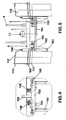
- the Fig. 4 and 5 represent, respectively of profile and face, an embodiment of the counterweight according to the invention.
- the carriage is generally designated 101.
- the chassis of the carriage consists of four longitudinal beams, two outer beams 102 and two inner beams 103, connected by four transverse beams 104.
- Each beam 102, 103 carries two rolling devices. with rollers 105 which roll on the two curvilinear rails 2 and 3 constituting the raceway.
- the outer longitudinal beams 102 each carry three substantially vertical support beams, namely an upper beam 106 and two lower beams 107, constituting three points of support.
- Each longitudinal beam 102 also carries two support arms 108, 109.
- These support arms are preferably mounted inclined to eliminate the play between ballast elements, which are supported against each other, and against the support points. .
- the support arms, and the corresponding fastening means of the ballast elements are arranged so that the level of the center of gravity of the counterweight is close to, and preferably substantially coincides with the level of the raceway at the location where is the trolley, to avoid swaying movements of the crane.
- the support arms can be mounted on joints to fold them, in order to reduce the size of the carriage during transport.
- Each pair of unfolded arms 108, 109 receives one or more weight (s) of ballast 110.
- these ballast masses may consist of concrete plates provided with two holes for hanging them on the support arms 108 and 109.
- the holes 111 may be made in the form of two squares rotated angularly by 90 ° relative to each other. at the other and spaced apart from one another so that the support arms 108 and 109 are placed in the corners as shown in FIG. Fig. 2 .
- this arrangement allows both an easy placement of the weights on the support arms, the dimensions of the holes 111 being significantly greater than the diameter of the support arms 108 and 109, and on the other hand avoids a tilting masses and corresponding shocks when the movable carriage moves between the zone A and the areas B and C of the raceway.
- the establishment of the weights on the carriage is completed by the establishment of a set of bars 113 and safety cables 112 between the support arm and support beams of the carriage.
- ballast 110 offer to the lateral wind a large surface.
- the action of the wind on it therefore generates a torque that partially compensates for the torque that the wind exerts on the boom.
- This arrangement and this conformation of the ballast plates thus assists the horizontal rotation of the rotating part above the pivot, that is to say the distribution of the charges.
- the two curvilinear rails 2 and 3 are connected by a set of transverse beams 4 thus constituting a kind of platform which can receive one or more winches 17, punches or tie rods 6.
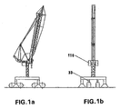
- Fig. 1a and 1b show an articulated boom crane, with the boom raised to the maximum and the dart folded against the boom foot, on a rolling chassis.
- the ballast masses come very close to the pylon, framing it on both sides, as shown in the diagram.
- Fig. 1b In this position, the ballast masses on the one hand and the mass of the boom on the other hand exert relatively low stresses on the tower and the rolling chassis of the crane, so that the displacement of the standing crane is possible on the yard, by means of a chase, without there being need to disassemble the crane to move it.
- Jacks 33 can raise and adjust the level of the crane during such a displacement.
- the Fig. 6a and 6b show the operation of the counterweight on a hoist whose boom operates in working mode.
- the Fig. 6a shows the machine, the arrow 10 is almost horizontal, in maximum range position.
- the counterweight 100 represented in a simplified manner by a square ballast and a set of rollers, rolls on the guideway 1 and is connected to the boom only by the sling (s) 11, so that its displacement is enslaved to the displacement of the arrow simply and only by this (these) sling (s) 11.
- the counterweight 100 is in the distal zone of the lane 1 relative to the axis of the tower.
- the arrow 10 is raised in the minimum range position.
- the boom retention sling 11 is fixed at its first end to the counterweight 100. It passes over a deflection pulley 9 arranged at the distal end of the guideway and a second deflection pulley 8 arranged at the top of the punch. 7.
- the other end of the retaining sling 11 is fixed at 12 to the arrow, at the same level as the bridge 13.
- the bridge 13 serves as a point of attachment to the lifting device.
- the lifting device may consist of several parts, namely a lifting tie 14, connecting the lifting bridge to a pulley or a block 16, and a lifting cable 15, which can make several strands of muffle.
- the lifting cable 15 is connected to a winch of lift 17 whose coil is arranged on the platform secured to the guideway.
- the boom retaining sling 11 cooperates with the lifting engine device to raise the boom.
- the counterweight system according to the invention therefore makes it possible to reduce the maximum nominal torque of the lifting device. If it is desired to obtain a return component F assisting the lifting device to the maximum in positions close to that of the Fig. 6a , the guideway may have its steepest slope in its distal portion.
- arrow 10 shown on the Fig. 6a and 6b can be a rigid boom or an articulated boom like that of the Fig. 7c .
- the Fig. 7a, 7b and 7c illustrate the operation of an articulated boom operating in horizontal articulated distribution mode.
- the Fig. 7a similar to Fig. 1a , shows the arrow in the position of minimum range, dart 18 folded against foot of arrow 19.
- the Fig. 7c shows the arrow 10 in a position similar to that of the Fig. 6a in the maximum range position, the jib foot and the jib being aligned.
- the Fig. 7b shows the arrow in an intermediate deployment position.
- the skilled person will note in particular that in the position illustrated by the Fig. 7b , the counterweight 100 is about halfway and the traction component on the retaining sling 11 of the boom is important.
- the arrow lift tie 14 attached to the bridge 13 passes on the end 21 of the counter-dart 20 which returns it.
- the hinge 32 formed by a horizontal axis of rotation between the foot of the boom 19 and the dart 18 delimits the latter between dart tip 22 and against-dart 20. It is at this level that is attached in 12 the sling 11.
- the rotation of the dart about the hinge axis 32 is achieved by means of two opposing cables 23 and 24.
- the attachment point of the cable 23 is located at the end of the counter -flash 20 to obtain the largest lever arm relative to the hinge 32, to reduce the forces in the cable 23 and the required power of the electric winch 25 which actuates.
- the point of attachment of the cable 24 on the dart 22 is situated approximately at the same distance as the cable 23 with respect to the hinge 32.
- a pulley 29 of the cables 23, 24 is arranged in the foot of the arrow, in an area close to the articulation 32 between the foot of the arrow and the dart, as illustrated by FIG. figure 7b .
- the winding winches 25, 26 of the cables 23 and 24 are arranged in the jib foot near the articulation 27 of the first end of the jib foot at the top of the tower in order to obtain a better balance of the crane. bringing as much as possible the dead weight of the various elements of the winches 25 and 26 towards the center of the pylon. This location also improves maintenance because the winches are close to the swivel.
- the attachment point 12 of the sling 11, located on the dart 18, describes an arc around the hinge axis 32 to optimize the movement of the counterweight to improve the balance of the crane.
- the operation of the horizontal distribution from the minimum range ( Fig. 7a ) to the maximum range, Fig. 7c , in articulated work mode is illustrated in more detail by the Fig. 8a, 8b, 8c, 8d and 8th .
- the Fig. 8a shows the area of the arrow surrounding the 32 foot joint of arrow / dart in the position of the Fig. 7a .
- the boom retaining slings (s) pass (s) slightly below and to the right of the articulation 32 foot of arrow / dart; the lifting cable 15 and the lifting lever 14 boom run over the end 21 of the counter-dart and are a little to the left of the hinge 32 between the jib and arrow.
- the cables 23 and 24 have antagonistic effects. From this position, the upper cable 23 is controlled by the crane operator and the lower cable 24 is unwound. The upper cable 23 is deflected by the upper rod 30.
- the upper cable 23 always pulls on the counter-dart, in order to continue the deployment movement, but the upper rod 30 no longer deflects the upper cable 23.
- the lower cable 24 is always carried by the upper cable.
- the upper cable 23 always pulls on the counter-dart, to continue to deploy the boom, and the lower cable 24 is always carried by the upper cable. It will be noted that the lower cable 24 comes into contact with the lower rod 31 and that the retaining sling 11 has passed the hinge 32 between the jib and the jib.
- the lifting tie 14 In the position illustrated by the Fig. 8th the lifting tie 14 is no longer in contact with the end 21 of the counter-dart.
- the lower cane 31 increases the traction angle of the lower cable 24 in order to reduce the efforts of this and to ensure the stability of the elements around the joint 32.
- the return force contribution F of the boom retaining sling 11 decreases in favor of the torque C.
- the distal zone of the guide lane 1 indicated as zone C on the Fig. 2 may have a lower slope than the slope of zone B.
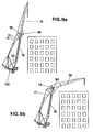
- the Fig. 9a and 9b illustrate the tilting jib work mode of the articulated boom previously described in relation to the groups of Fig. 7 and 8 .
- the boom foot 19 does not move, it bears against an abutment device 33.
- Such abutment devices are known in the state of the art.
- the mobile counterweight 100 is located in both positions in a low slope area of the raceway, near the pylon. However, because of the non-zero distance between the attachment point 12 of the boom retaining sling and the hinge 32 between the jib and dart, this attachment point 12 describes an arc around the articulation 32 of the arrow, driving the counterweight in a limited displacement.
- the resulting momentum variations of the counterweight to the pylon balance the variations in the moment of the weight of the boom due to the rotation of the dart.
- the rotation of the dart about the hinge 32 with the jib foot is provided by the opposing cable systems 24 and 23 in the same manner as explained above in connection with the group of Fig. 8 .
- the stability of the end of the boom is provided by a electromechanical brake with no current installed on the motors of the cables 23 and 24.
- the set of antagonistic cables 24 and 23 with their winding and unwinding winches 25, 26 arranged in the jib foot is replaced by a gear system 200, consisting of a motor 201, a gear 202 and a toothed segment 203, arranged at the hinge 232 between the jib 204 and the jib 205.
- the electric motor 201 is fixed on the jib foot, it drives a pinion 202 which itself meshes with a circular toothed segment 203 integral with the dart, to ensure the rotation of the dart around the hinge 232 between the foot of the arrow and the dart.
- the arrangement and function of the boom retainers 11 and the lift tie 14 are the same as those of the embodiments described above.
- the Fig. 11 schematically illustrates an exemplary embodiment of tower crane according to the invention.
- the base frame has an impregnation of 5 x 5 meters and carries a basic weight of 46 tons.
- the base frame is surmounted by a tower having a cabin height of 31 meters and a rotating pivot. This one carries the platform, the cabin and the arrow as well as the guide way on which the mobile ballast circulates.
- the total weight of the idling crane in service is 111.6 tons.
- the guiding track integral with the rotating pivot at the top of the pylon, extends from the pylon up to a distance of 12 meters from it. It consists of a pair of rails connected by spacers. Each rail comprises a first straight portion of slope 5 °, extending from the pivot pivot to a distance of 6 meters, a second rectilinear portion of slope 29 °, extending from a distance of 6 meters up to at a distance of 8 meters from the pylon, and a third rectilinear portion of slope 43 °, corresponding to the last two meters of the track. Between the first and second rectilinear portions on the one hand and the second and third rectilinear portions on the other hand are located two intermediate portions curved, forming the rounded rails, which are therefore generally curvilinear.
- the guideway which is also the platform, carries the boom lifting winch which has a power of 22 kW.
- the guideway is surmounted by a set of punches and tie rods carrying the pulleys. The whole stands at a height of about 41.6 meters.
- the boom foot near its articulation with the rotating pivot of the tower, the boom deployment / folding winches in articulated working mode with a power of 7.5 kW and the hoist winch of the load of a power of 45 kW.
- the corresponding return pulleys are also housed in the foot of the arrow near the joint with the dart.
- the operating mode of the articulated boom has been described above in relation to the Fig. 6a to 8e .
- the crane can deliver a maximum load of 12 tons at reduced speed, or a load of 10 tons at normal speed, and this in an area from 2 to 20 meters from the foot of the pylon.
- the distributable load decreases at a greater distance from the foot of the pylon.
- the maximum load is 5.6 tonnes at reduced speed and 4.7 tonnes at normal speed at the maximum working range, that is to say 47 meters.
- the speed of distribution can vary from 0 to 60 meters per minute.
- the maximum distributable load is 12 tonnes when the range is between 5 and 20 meters.
- the maximum load is reduced to 5.6 tons at a maximum range of 47 meters.
- the maximum height under hook in lift mode is 80 meters.
- the movement speed in lift mode can vary from 0 to 30 meters per minute.
- the crane When the crane is dismantled, it can be transported in parts by means of five trailers of lengths between 6 and 12 meters, each of the trailers carrying a set of parts from 19.5 to 25 tons.
- the boom lift winch can be removed and the lift block is replaced by two tie rods. This reduces the sale price of the crane and the number of parts.
Landscapes
- Engineering & Computer Science (AREA)
- Mechanical Engineering (AREA)
- Jib Cranes (AREA)
- Valve Device For Special Equipments (AREA)
- Magnetic Heads (AREA)
- Forklifts And Lifting Vehicles (AREA)
- Earth Drilling (AREA)
Claims (18)
- Vorrichtung zum Heben und Handhaben von Lasten mit schwenkbarem und gelenkigem Verteilerausleger, umfassend einen Mast mit einem Drehzapfen, einen gelenkigen Ausleger (10) mit einem Auslegerfuß (19), welcher an seinem ersten Ende über eine horizontale Drehachse (27) an die Spitze des Mastes angelenkt ist, einen Spitzenausleger (18), welcher über eine horizontal zum zweiten Ende des Auslegerfußes verlaufende Gelenkachse (32) drehbar angelenkt ist, eine Einheit zum Halten des Auslegers, die mindestens eine Stange (7), eine Schlinge zum Halten (11) des Auslegers und ein bewegliches Gegengewicht (100) umfasst, welches über diese Halteschlinge mit dem Ausleger verbunden ist und so gesteuert wird, dass es einer Führungsbahn (1) mit veränderlicher Neigung (α) folgt, wobei die Führungsbahn (1) entgegengesetzt zum Ausleger angeordnet ist und das Gegengewicht trägt, dadurch gekennzeichnet, dass die Führungsbahn starr am Drehzapfen befestigt ist und in einem näher beim Mast gelegenen Abschnitt (A) eine Neigung (αA) aufweist, die geringer als die Neigung (αB) in mindestens einem weiter vom Mast entfernten Abschnitt (B) ist, wobei die Neigung (αA) einen Winkel von 2° bis 25° mit der Horizontalen und die Neigung (αB) einen Winkel in der Größenordnung von 15° bis 85° mit der Horizontalen bildet, und dass die Änderungen der Neigung (α) so gewählt werden, dass das Gegengewicht eine Reihe veränderlicher Kräfte auf diesen Ausleger und auf die Konstruktion der Vorrichtung ausübt und dazu beiträgt, die Vorrichtung während der Bewegungen zum Ausfahren/Einziehen des Auslegers im Gelenkbetrieb im Gleichgewicht zu halten.
- Hebevorrichtung nach Anspruch 1, dadurch gekennzeichnet, dass die Schlinge (11) vom Gegengewicht aus über eine Umlenkscheibe (9) läuft, die am distalen Ende der Führungsbahn angeordnet ist, und über eine zweite Umlenkscheibe (8), die an der Spitze der Stange (7) angeordnet ist.
- Hebevorrichtung nach einem der Ansprüche 1 oder 2, dadurch gekennzeichnet, dass die Führungsbahn (1) ein kurvilineares Profil aufweist.
- Hebevorrichtung nach einem der Ansprüche 1 oder 2, dadurch gekennzeichnet, dass die Führungsbahn (1) ein sigmoidales Profil aufweist.
- Hebevorrichtung nach einem der vorangehenden Ansprüche, dadurch gekennzeichnet, dass die Führungsbahn (1) aus einem Paar paralleler kurvilinearer Schienen (2, 3) besteht, dass das Gegengewicht einen beweglichen Wagen (101) umfasst, der Laufmittel (105), die auf diesen Schienen laufen, und Ballastelemente (110), die von diesem Wagen getragen werden, umfasst.
- Hebevorrichtung nach Anspruch 5, dadurch gekennzeichnet, dass der Wagen (101) ein Chassis (102, 103, 104) umfasst und an jeder Längsseite des Chassis Tragelemente (108, 109) zum Aufnehmen und Tragen der Ballastelemente (110) beiderseits der Schienen, so dass die Höhe des Schwerpunkts des Gegengewichts nahe der Höhe der Führungsbahn liegt.
- Hebevorrichtung nach einem der Ansprüche 5 oder 6, dadurch gekennzeichnet, dass diese Tragelemente (108, 109) schräg angeordnete Armpaare sind, dass die Ballastelemente (110) aus Platten bestehen, die jeweils Löcher (111) aufweisen, deren Fläche größer als der Querschnitt der Tragelemente (108, 109) ist und die so gestaltet sind, dass eine Ballastplatte, die an einem zugehörigen Tragarmpaar hängt, unabhängig von der Position des Wagens an der Führungsbahn (1) in einer in Bezug auf den Wagen (101) unbeweglichen Position und parallel zur Führungsbahn (1) gehalten wird.
- Hebevorrichtung nach Anspruch 7, dadurch gekennzeichnet, dass diese Tragarme einziehbar sind.
- Hebevorrichtung nach einem beliebigen der vorangehenden Ansprüche, dadurch gekennzeichnet, dass sie eine Einrichtung zum Heben des Auslegers (14, 15, 17) umfasst, die die Vorrichtung in die Lage versetzt, im Gelenkbetrieb und im Hebe- und Senkbetrieb zu arbeiten, dass der Spitzenausleger beiderseits seiner Gelenkachse (32) am Auslegerfuß eine Spitzenausleger-Spitze (22) und ein Spitzenausleger-Gegenstück (20) umfasst, wobei das zweite Ende des Auslegerfußes und das Spitzenausleger-Gegenstück einander zugeordnete Formen aufweisen, die es der Spitzenausleger-Spitze ermöglichen, in der Hebe- und Senk-Arbeitsposition eine mit dem Auslegerfuß fluchtende Position einzunehmen, und dass die Änderungen der Neigung der Führungsbahn (1) so gewählt werden, dass der veränderliche Zug am Ausleger die Hebeeinrichtung und/oder die Änderungen der Gestalt des Auslegers im Zusammenhang mit einem Wechsel der Betriebsart unterstützt.
- Hebevorrichtung nach einem beliebigen der vorangehenden Ansprüche, dadurch gekennzeichnet, dass das Ende der Schlinge zum Halten (11) des Auslegers am Spitzenausleger befestigt ist.
- Hebevorrichtung nach Anspruch 10, dadurch gekennzeichnet, dass der Befestigungspunkt (12) des Endes der Schlinge zum Halten (11) des Auslegers zwischen der Spitzenausleger-Spitze (22) und dem Spitzenausleger-Gegenstück (20) angeordnet ist.
- Hebevorrichtung nach Anspruch 11, dadurch gekennzeichnet, dass der Befestigungspunkt (12) in einem solchen Abstand vom Gelenk (32) zwischen Auslegerfuß und Spitzenausleger angeordnet ist, dass er einen Kreisbogen um die Gelenkachse (32) beschreibt, und dass die Schlinge zum Halten (11) des Auslegers die Gelenkachse (32) Auslegerfuß/Spitzenausleger während des Ausfahrens des Auslegers im Gelenkbetrieb zwischen der Position der kleinsten Ausladung und der Position der größten Ausladung kreuzt.
- Hebevorrichtung nach einem beliebigen der vorangehenden Anspruche, dadurch gekennzeichnet, dass die Drehung des Spitzenauslegers (18) um das Gelenk (32) Auslegerfuß/Spitzenausleger über ein System aus gegenläufigen Seilen (23, 24) betätigt wird.
- Hebevorrichtung nach Anspruch 13, dadurch gekennzeichnet, dass das erste Seil (23) am Ende des Spitzenausleger-Gegenstücks (20) befestigt ist und dass das zweite Seil (24) an der Spitze des Spitzenauslegers befestigt ist, wobei der Abstand vom Gelenk (32) in etwa genauso groß ist wie der Abstand des Befestigungspunkts des Seils (23) vom Gelenk (32).
- Hebevorrichtung nach Anspruch 13 oder 14, dadurch gekennzeichnet, dass das System aus gegenläufigen Seilen (23, 24) elektrische Winden (25, 26) und Umlenkscheiben (29) umfasst, die im Auslegerfuß (19) untergebracht sind.
- Hebevorrichtung nach Anspruch 15, dadurch gekennzeichnet, dass die elektrischen Winden (25, 26) in der Nähe des ersten Endes des Auslegerfußes (19) und die Umlenkscheiben (29) in der Nähe des zweiten Endes des Auslegerfußes (19) untergebracht sind.
- Hebevorrichtung nach einem der Ansprüche 1 bis 12, dadurch gekennzeichnet, dass die Drehung des Spitzenauslegers (205) um das Ende des Auslegerfußes (204) über ein Getriebesystem (200) erfolgt, das einen Elektromotor (201), ein Ritzel (202) und ein gezahntes Segment (203) umfasst.
- Hebevorrichtung nach Anspruch 17, dadurch gekennzeichnet, dass der Elektromotor (201) am Auslegerfuß (204) befestigt ist und über das Ritzel (202) ein kreisförmiges gezahntes Segment (203) antreibt, das fest mit dem Spitzenausleger (205) verbunden ist.
Priority Applications (1)
| Application Number | Priority Date | Filing Date | Title |
|---|---|---|---|
| EP04761917A EP1667931B1 (de) | 2003-09-15 | 2004-09-14 | Hebevorrichtung |
Applications Claiming Priority (3)
| Application Number | Priority Date | Filing Date | Title |
|---|---|---|---|
| EP03405677A EP1514832A1 (de) | 2003-09-15 | 2003-09-15 | Hebezeug |
| PCT/CH2004/000577 WO2005026036A1 (fr) | 2003-09-15 | 2004-09-14 | Engin de levage |
| EP04761917A EP1667931B1 (de) | 2003-09-15 | 2004-09-14 | Hebevorrichtung |
Publications (2)
| Publication Number | Publication Date |
|---|---|
| EP1667931A1 EP1667931A1 (de) | 2006-06-14 |
| EP1667931B1 true EP1667931B1 (de) | 2009-10-21 |
Family
ID=34130421
Family Applications (2)
| Application Number | Title | Priority Date | Filing Date |
|---|---|---|---|
| EP03405677A Withdrawn EP1514832A1 (de) | 2003-09-15 | 2003-09-15 | Hebezeug |
| EP04761917A Expired - Lifetime EP1667931B1 (de) | 2003-09-15 | 2004-09-14 | Hebevorrichtung |
Family Applications Before (1)
| Application Number | Title | Priority Date | Filing Date |
|---|---|---|---|
| EP03405677A Withdrawn EP1514832A1 (de) | 2003-09-15 | 2003-09-15 | Hebezeug |
Country Status (7)
| Country | Link |
|---|---|
| US (1) | US7331476B2 (de) |
| EP (2) | EP1514832A1 (de) |
| AT (1) | ATE446275T1 (de) |
| AU (1) | AU2004272136A1 (de) |
| CA (1) | CA2539014A1 (de) |
| DE (1) | DE602004023738D1 (de) |
| WO (1) | WO2005026036A1 (de) |
Families Citing this family (17)
| Publication number | Priority date | Publication date | Assignee | Title |
|---|---|---|---|---|
| US7967158B2 (en) | 2006-10-27 | 2011-06-28 | Manitowoc Crane Companies, Llc | Mobile lift crane with variable position counterweight |
| US7546928B2 (en) * | 2006-10-27 | 2009-06-16 | Manitowoc Crane Companies, Inc. | Mobile lift crane with variable position counterweight |
| US9278834B2 (en) | 2009-08-06 | 2016-03-08 | Manitowoc Crane Group, LLC | Lift crane with moveable counterweight |
| CN102259801B (zh) * | 2011-04-28 | 2013-06-05 | 上海三一科技有限公司 | 桁架臂履带起重机用折叠臂架 |
| CN102849624B (zh) * | 2011-06-29 | 2016-12-21 | 利勃海尔爱茵根有限公司 | 操作起重机的方法和起重机 |
| DE102012006494B4 (de) | 2012-03-30 | 2014-03-13 | Manitowoc Crane Group France Sas | Fahrzeugkran mit entkoppelbarer Gegengewichtsanordnung |
| CN102756978A (zh) * | 2012-07-20 | 2012-10-31 | 辽宁抚挖重工机械股份有限公司 | 一种履带起重机折叠臂 |
| NO2694106T3 (de) * | 2012-09-12 | 2018-05-12 | ||
| CN103318781B (zh) * | 2012-11-01 | 2015-05-13 | 上海振华重工(集团)股份有限公司 | 用于码头的折臂大梁起重机 |
| CN102942125B (zh) * | 2012-12-12 | 2014-10-22 | 中联重科股份有限公司 | 副臂尾架及包含该副臂尾架的副臂、起重设备 |
| US10183848B2 (en) | 2014-01-27 | 2019-01-22 | Manitowoc Crane Companies, Llc | Height adjustment mechanism for an auxiliary member on a crane |
| CN110255402B (zh) | 2014-01-27 | 2022-02-18 | 马尼托瓦克起重机有限责任公司 | 带有改进的可动配重的吊升起重机 |
| JP6816647B2 (ja) * | 2017-05-26 | 2021-01-20 | コベルコ建機株式会社 | ジブ引込装置およびジブ引込方法 |
| CN107717949A (zh) * | 2017-11-23 | 2018-02-23 | 苏州夏木自动化科技有限公司 | 地面移动式助力机械手 |
| JP7626641B2 (ja) | 2021-03-23 | 2025-02-04 | 株式会社北川鉄工所 | クライミングクレーン及びクライミングクレーンを用いた工事方法 |
| CN115611173A (zh) * | 2022-09-08 | 2023-01-17 | 三一海洋重工有限公司 | 一种前大梁俯仰机构及岸桥 |
| CN116002522A (zh) * | 2022-12-13 | 2023-04-25 | 徐工集团工程机械股份有限公司建设机械分公司 | 一种臂架快速拆装辅助平台 |
Family Cites Families (15)
| Publication number | Priority date | Publication date | Assignee | Title |
|---|---|---|---|---|
| DE279083C (de) * | ||||
| DE261429C (de) * | ||||
| DE289839C (de) * | ||||
| US834647A (en) * | 1906-05-15 | 1906-10-30 | Humphrey Toomey | Hoisting apparatus. |
| US2521861A (en) * | 1949-03-22 | 1950-09-12 | Berton M Mathias | Crane with portable boom |
| US2703180A (en) * | 1952-01-05 | 1955-03-01 | American Hoist & Derrick Co | Crane |
| US3062384A (en) * | 1962-05-11 | 1962-11-06 | Seljo Dev Corp | Boom and jib assembly |
| DE1260733B (de) | 1966-05-04 | 1968-02-08 | Herbert Biedermann Dipl Ing | Wippkran, insbesondere Turmdrehkran |
| SU524762A1 (ru) * | 1973-04-23 | 1976-08-15 | Предприятие П/Я Г-4448 | Устройство дл уравновешивани грузоподъемных машин |
| DE3438937C2 (de) | 1984-10-24 | 1996-12-19 | Liebherr Werk Biberach Gmbh | Turmdrehkran mit verstellbarem Gegengewicht |
| DD253240A1 (de) * | 1986-10-13 | 1988-01-13 | Univ Magdeburg Tech | Lastmomentenausgleich fuer hubeinrichtungen mit ausleger |
| FR2605619B1 (fr) | 1986-10-27 | 1989-03-31 | Potain Sa | Engin repliable pour la manutention et le levage des charges |
| FR2641773B1 (fr) * | 1989-01-18 | 1991-03-15 | Potain Sa | Grue a fleche relevable avec dispositif de renvoi de fleche |
| DE69919517T2 (de) * | 1999-06-02 | 2005-09-29 | Jean-Marc Yerly | Kran mit aus Gliedern bestehendem Kranarm |
| EP1172323A1 (de) * | 2000-07-11 | 2002-01-16 | Jean-Marc Yerly | Kran mit aus Gliedern bestehendem Kranarm |
-
2003
- 2003-09-15 EP EP03405677A patent/EP1514832A1/de not_active Withdrawn
-
2004
- 2004-09-14 EP EP04761917A patent/EP1667931B1/de not_active Expired - Lifetime
- 2004-09-14 US US10/571,982 patent/US7331476B2/en not_active Expired - Fee Related
- 2004-09-14 AU AU2004272136A patent/AU2004272136A1/en not_active Abandoned
- 2004-09-14 AT AT04761917T patent/ATE446275T1/de not_active IP Right Cessation
- 2004-09-14 WO PCT/CH2004/000577 patent/WO2005026036A1/fr not_active Ceased
- 2004-09-14 CA CA002539014A patent/CA2539014A1/en not_active Abandoned
- 2004-09-14 DE DE602004023738T patent/DE602004023738D1/de not_active Expired - Lifetime
Also Published As
| Publication number | Publication date |
|---|---|
| AU2004272136A1 (en) | 2005-03-24 |
| US7331476B2 (en) | 2008-02-19 |
| CA2539014A1 (en) | 2005-03-24 |
| DE602004023738D1 (de) | 2009-12-03 |
| ATE446275T1 (de) | 2009-11-15 |
| EP1514832A1 (de) | 2005-03-16 |
| US20060283826A1 (en) | 2006-12-21 |
| EP1667931A1 (de) | 2006-06-14 |
| WO2005026036A1 (fr) | 2005-03-24 |
Similar Documents
| Publication | Publication Date | Title |
|---|---|---|
| EP1667931B1 (de) | Hebevorrichtung | |
| EP1301431B9 (de) | Kran mit aus gliedern bestehendem kranarm | |
| FR3008403A1 (fr) | Grue sur tour orientable | |
| EP1048605B1 (de) | Multifunktionskran mit einem Teleskopausleger | |
| EP3184481B1 (de) | Turmkran mit automatischer ein- und ausklappfunktion, der einen mast und einen zum mast versetzten ausleger umfasst | |
| FR2682097A1 (fr) | Fleche a repliage automatise pour grue. | |
| FR2605619A1 (fr) | Engin repliable pour la manutention et le levage des charges | |
| EP1184328A1 (de) | Seilanordnung für einen Turmkran | |
| WO2006111827A1 (fr) | Dispositif d'aide a la construction de murs et/ou au traitement de surfaces | |
| FR2521969A1 (fr) | Machine transportable sur vehicule, pouvant elever une nacelle a des hauteurs differentes | |
| EP0360702B1 (de) | Zusammenlegbarer Kran mit einem Ausleger, bestehend aus zwei oder drei gelenkig miteinander verbundenen Elementen | |
| EP1061034B1 (de) | Selbstangetriebener Wagen mit teleskopischem Arm und Hebungarm | |
| EP0536061A1 (de) | Automatisch zusammenklappbarer Turmkran | |
| FR2822145A1 (fr) | Nacelle elevatrice avec plate-forme et structure de support de charge associee | |
| FR2885611A1 (fr) | Etabli elevateur | |
| EP1953112B1 (de) | Hubgerät | |
| FR2636616A1 (fr) | Grue repliable a fleche en deux ou trois elements articules les uns aux autres | |
| EP1927570B1 (de) | Kranmast mit Gegengewicht | |
| EP1057776B1 (de) | Kran mit aus Gliedern bestehendem Kranarm | |
| EP0612899A1 (de) | Gerüstboden und Montageverfahren für Gerüste mit diesem Boden | |
| FR2626865A1 (fr) | Nacelle pour fleche telescopique d'engin de levage | |
| BE1006161A7 (fr) | Dispositif a godet elevateur pour des materiaux, notamment dans une centrale de fabrication de beton. | |
| BE1031824A1 (fr) | Structure de support temporaire pour montage et démontage de pont de grue à portique et procédé de construction | |
| EP2544984B1 (de) | Bewegliche hebeausrüstung | |
| BE513255A (de) |
Legal Events
| Date | Code | Title | Description |
|---|---|---|---|
| PUAI | Public reference made under article 153(3) epc to a published international application that has entered the european phase |
Free format text: ORIGINAL CODE: 0009012 |
|
| 17P | Request for examination filed |
Effective date: 20060411 |
|
| AK | Designated contracting states |
Kind code of ref document: A1 Designated state(s): AT BE BG CH CY CZ DE DK EE ES FI FR GB GR HU IE IT LI LU MC NL PL PT RO SE SI SK TR |
|
| 17Q | First examination report despatched |
Effective date: 20060719 |
|
| DAX | Request for extension of the european patent (deleted) | ||
| GRAP | Despatch of communication of intention to grant a patent |
Free format text: ORIGINAL CODE: EPIDOSNIGR1 |
|
| GRAS | Grant fee paid |
Free format text: ORIGINAL CODE: EPIDOSNIGR3 |
|
| GRAA | (expected) grant |
Free format text: ORIGINAL CODE: 0009210 |
|
| AK | Designated contracting states |
Kind code of ref document: B1 Designated state(s): AT BE BG CH CY CZ DE DK EE ES FI FR GB GR HU IE IT LI LU MC NL PL PT RO SE SI SK TR |
|
| REG | Reference to a national code |
Ref country code: GB Ref legal event code: FG4D Free format text: NOT ENGLISH |
|
| REG | Reference to a national code |
Ref country code: CH Ref legal event code: EP |
|
| REG | Reference to a national code |
Ref country code: IE Ref legal event code: FG4D |
|
| REF | Corresponds to: |
Ref document number: 602004023738 Country of ref document: DE Date of ref document: 20091203 Kind code of ref document: P |
|
| REG | Reference to a national code |
Ref country code: CH Ref legal event code: NV Representative=s name: ABREMA AGENCE BREVET ET MARQUES, GANGUILLET |
|
| NLV1 | Nl: lapsed or annulled due to failure to fulfill the requirements of art. 29p and 29m of the patents act | ||
| PG25 | Lapsed in a contracting state [announced via postgrant information from national office to epo] |
Ref country code: FI Free format text: LAPSE BECAUSE OF FAILURE TO SUBMIT A TRANSLATION OF THE DESCRIPTION OR TO PAY THE FEE WITHIN THE PRESCRIBED TIME-LIMIT Effective date: 20091021 Ref country code: ES Free format text: LAPSE BECAUSE OF FAILURE TO SUBMIT A TRANSLATION OF THE DESCRIPTION OR TO PAY THE FEE WITHIN THE PRESCRIBED TIME-LIMIT Effective date: 20100201 Ref country code: SE Free format text: LAPSE BECAUSE OF FAILURE TO SUBMIT A TRANSLATION OF THE DESCRIPTION OR TO PAY THE FEE WITHIN THE PRESCRIBED TIME-LIMIT Effective date: 20091021 |
|
| REG | Reference to a national code |
Ref country code: IE Ref legal event code: FD4D |
|
| PG25 | Lapsed in a contracting state [announced via postgrant information from national office to epo] |
Ref country code: PL Free format text: LAPSE BECAUSE OF FAILURE TO SUBMIT A TRANSLATION OF THE DESCRIPTION OR TO PAY THE FEE WITHIN THE PRESCRIBED TIME-LIMIT Effective date: 20091021 Ref country code: SI Free format text: LAPSE BECAUSE OF FAILURE TO SUBMIT A TRANSLATION OF THE DESCRIPTION OR TO PAY THE FEE WITHIN THE PRESCRIBED TIME-LIMIT Effective date: 20091021 |
|
| PG25 | Lapsed in a contracting state [announced via postgrant information from national office to epo] |
Ref country code: AT Free format text: LAPSE BECAUSE OF FAILURE TO SUBMIT A TRANSLATION OF THE DESCRIPTION OR TO PAY THE FEE WITHIN THE PRESCRIBED TIME-LIMIT Effective date: 20091021 |
|
| PG25 | Lapsed in a contracting state [announced via postgrant information from national office to epo] |
Ref country code: RO Free format text: LAPSE BECAUSE OF FAILURE TO SUBMIT A TRANSLATION OF THE DESCRIPTION OR TO PAY THE FEE WITHIN THE PRESCRIBED TIME-LIMIT Effective date: 20091021 Ref country code: IE Free format text: LAPSE BECAUSE OF FAILURE TO SUBMIT A TRANSLATION OF THE DESCRIPTION OR TO PAY THE FEE WITHIN THE PRESCRIBED TIME-LIMIT Effective date: 20091021 Ref country code: EE Free format text: LAPSE BECAUSE OF FAILURE TO SUBMIT A TRANSLATION OF THE DESCRIPTION OR TO PAY THE FEE WITHIN THE PRESCRIBED TIME-LIMIT Effective date: 20091021 Ref country code: DK Free format text: LAPSE BECAUSE OF FAILURE TO SUBMIT A TRANSLATION OF THE DESCRIPTION OR TO PAY THE FEE WITHIN THE PRESCRIBED TIME-LIMIT Effective date: 20091021 Ref country code: BG Free format text: LAPSE BECAUSE OF FAILURE TO SUBMIT A TRANSLATION OF THE DESCRIPTION OR TO PAY THE FEE WITHIN THE PRESCRIBED TIME-LIMIT Effective date: 20100121 |
|
| PLBE | No opposition filed within time limit |
Free format text: ORIGINAL CODE: 0009261 |
|
| STAA | Information on the status of an ep patent application or granted ep patent |
Free format text: STATUS: NO OPPOSITION FILED WITHIN TIME LIMIT |
|
| PG25 | Lapsed in a contracting state [announced via postgrant information from national office to epo] |
Ref country code: SK Free format text: LAPSE BECAUSE OF FAILURE TO SUBMIT A TRANSLATION OF THE DESCRIPTION OR TO PAY THE FEE WITHIN THE PRESCRIBED TIME-LIMIT Effective date: 20091021 Ref country code: CZ Free format text: LAPSE BECAUSE OF FAILURE TO SUBMIT A TRANSLATION OF THE DESCRIPTION OR TO PAY THE FEE WITHIN THE PRESCRIBED TIME-LIMIT Effective date: 20091021 |
|
| 26N | No opposition filed |
Effective date: 20100722 |
|
| PG25 | Lapsed in a contracting state [announced via postgrant information from national office to epo] |
Ref country code: GR Free format text: LAPSE BECAUSE OF FAILURE TO SUBMIT A TRANSLATION OF THE DESCRIPTION OR TO PAY THE FEE WITHIN THE PRESCRIBED TIME-LIMIT Effective date: 20100122 |
|
| PG25 | Lapsed in a contracting state [announced via postgrant information from national office to epo] |
Ref country code: IT Free format text: LAPSE BECAUSE OF FAILURE TO SUBMIT A TRANSLATION OF THE DESCRIPTION OR TO PAY THE FEE WITHIN THE PRESCRIBED TIME-LIMIT Effective date: 20091021 |
|
| PG25 | Lapsed in a contracting state [announced via postgrant information from national office to epo] |
Ref country code: MC Free format text: LAPSE BECAUSE OF NON-PAYMENT OF DUE FEES Effective date: 20100930 |
|
| PG25 | Lapsed in a contracting state [announced via postgrant information from national office to epo] |
Ref country code: CY Free format text: LAPSE BECAUSE OF FAILURE TO SUBMIT A TRANSLATION OF THE DESCRIPTION OR TO PAY THE FEE WITHIN THE PRESCRIBED TIME-LIMIT Effective date: 20091021 |
|
| PG25 | Lapsed in a contracting state [announced via postgrant information from national office to epo] |
Ref country code: HU Free format text: LAPSE BECAUSE OF FAILURE TO SUBMIT A TRANSLATION OF THE DESCRIPTION OR TO PAY THE FEE WITHIN THE PRESCRIBED TIME-LIMIT Effective date: 20100422 Ref country code: LU Free format text: LAPSE BECAUSE OF NON-PAYMENT OF DUE FEES Effective date: 20100914 Ref country code: NL Free format text: LAPSE BECAUSE OF FAILURE TO SUBMIT A TRANSLATION OF THE DESCRIPTION OR TO PAY THE FEE WITHIN THE PRESCRIBED TIME-LIMIT Effective date: 20091021 |
|
| PG25 | Lapsed in a contracting state [announced via postgrant information from national office to epo] |
Ref country code: TR Free format text: LAPSE BECAUSE OF FAILURE TO SUBMIT A TRANSLATION OF THE DESCRIPTION OR TO PAY THE FEE WITHIN THE PRESCRIBED TIME-LIMIT Effective date: 20091021 |
|
| PGFP | Annual fee paid to national office [announced via postgrant information from national office to epo] |
Ref country code: GB Payment date: 20120920 Year of fee payment: 9 |
|
| PGFP | Annual fee paid to national office [announced via postgrant information from national office to epo] |
Ref country code: DE Payment date: 20120921 Year of fee payment: 9 |
|
| PGFP | Annual fee paid to national office [announced via postgrant information from national office to epo] |
Ref country code: BE Payment date: 20120920 Year of fee payment: 9 Ref country code: FR Payment date: 20121010 Year of fee payment: 9 Ref country code: CH Payment date: 20121005 Year of fee payment: 9 |
|
| PG25 | Lapsed in a contracting state [announced via postgrant information from national office to epo] |
Ref country code: PT Free format text: LAPSE BECAUSE OF NON-PAYMENT OF DUE FEES Effective date: 20091021 |
|
| BERE | Be: lapsed |
Owner name: YERLY, JEAN-MARC Effective date: 20130930 |
|
| REG | Reference to a national code |
Ref country code: CH Ref legal event code: PL |
|
| GBPC | Gb: european patent ceased through non-payment of renewal fee |
Effective date: 20130914 |
|
| REG | Reference to a national code |
Ref country code: DE Ref legal event code: R119 Ref document number: 602004023738 Country of ref document: DE Effective date: 20140401 |
|
| REG | Reference to a national code |
Ref country code: FR Ref legal event code: ST Effective date: 20140530 |
|
| PG25 | Lapsed in a contracting state [announced via postgrant information from national office to epo] |
Ref country code: GB Free format text: LAPSE BECAUSE OF NON-PAYMENT OF DUE FEES Effective date: 20130914 Ref country code: CH Free format text: LAPSE BECAUSE OF NON-PAYMENT OF DUE FEES Effective date: 20130930 Ref country code: BE Free format text: LAPSE BECAUSE OF NON-PAYMENT OF DUE FEES Effective date: 20130930 Ref country code: LI Free format text: LAPSE BECAUSE OF NON-PAYMENT OF DUE FEES Effective date: 20130930 |
|
| PG25 | Lapsed in a contracting state [announced via postgrant information from national office to epo] |
Ref country code: FR Free format text: LAPSE BECAUSE OF NON-PAYMENT OF DUE FEES Effective date: 20130930 Ref country code: DE Free format text: LAPSE BECAUSE OF NON-PAYMENT OF DUE FEES Effective date: 20140401 |