EP1668748B1 - Laser à disque à l'état solide à pompage latéral de puissance moyenne élevée - Google Patents
Laser à disque à l'état solide à pompage latéral de puissance moyenne élevée Download PDFInfo
- Publication number
- EP1668748B1 EP1668748B1 EP04783804A EP04783804A EP1668748B1 EP 1668748 B1 EP1668748 B1 EP 1668748B1 EP 04783804 A EP04783804 A EP 04783804A EP 04783804 A EP04783804 A EP 04783804A EP 1668748 B1 EP1668748 B1 EP 1668748B1
- Authority
- EP
- European Patent Office
- Prior art keywords
- laser
- optical
- gain medium
- medium
- bank according
- Prior art date
- Legal status (The legal status is an assumption and is not a legal conclusion. Google has not performed a legal analysis and makes no representation as to the accuracy of the status listed.)
- Expired - Lifetime
Links
Images









Classifications
-
- H—ELECTRICITY
- H01—ELECTRIC ELEMENTS
- H01S—DEVICES USING THE PROCESS OF LIGHT AMPLIFICATION BY STIMULATED EMISSION OF RADIATION [LASER] TO AMPLIFY OR GENERATE LIGHT; DEVICES USING STIMULATED EMISSION OF ELECTROMAGNETIC RADIATION IN WAVE RANGES OTHER THAN OPTICAL
- H01S3/00—Lasers, i.e. devices using stimulated emission of electromagnetic radiation in the infrared, visible or ultraviolet wave range
- H01S3/02—Constructional details
- H01S3/025—Constructional details of solid state lasers, e.g. housings or mountings
-
- H—ELECTRICITY
- H01—ELECTRIC ELEMENTS
- H01S—DEVICES USING THE PROCESS OF LIGHT AMPLIFICATION BY STIMULATED EMISSION OF RADIATION [LASER] TO AMPLIFY OR GENERATE LIGHT; DEVICES USING STIMULATED EMISSION OF ELECTROMAGNETIC RADIATION IN WAVE RANGES OTHER THAN OPTICAL
- H01S3/00—Lasers, i.e. devices using stimulated emission of electromagnetic radiation in the infrared, visible or ultraviolet wave range
- H01S3/02—Constructional details
- H01S3/04—Arrangements for thermal management
- H01S3/042—Arrangements for thermal management for solid state lasers
-
- H—ELECTRICITY
- H01—ELECTRIC ELEMENTS
- H01S—DEVICES USING THE PROCESS OF LIGHT AMPLIFICATION BY STIMULATED EMISSION OF RADIATION [LASER] TO AMPLIFY OR GENERATE LIGHT; DEVICES USING STIMULATED EMISSION OF ELECTROMAGNETIC RADIATION IN WAVE RANGES OTHER THAN OPTICAL
- H01S3/00—Lasers, i.e. devices using stimulated emission of electromagnetic radiation in the infrared, visible or ultraviolet wave range
- H01S3/05—Construction or shape of optical resonators; Accommodation of active medium therein; Shape of active medium
- H01S3/06—Construction or shape of active medium
- H01S3/0602—Crystal lasers or glass lasers
- H01S3/0604—Crystal lasers or glass lasers in the form of a plate or disc
-
- H—ELECTRICITY
- H01—ELECTRIC ELEMENTS
- H01S—DEVICES USING THE PROCESS OF LIGHT AMPLIFICATION BY STIMULATED EMISSION OF RADIATION [LASER] TO AMPLIFY OR GENERATE LIGHT; DEVICES USING STIMULATED EMISSION OF ELECTROMAGNETIC RADIATION IN WAVE RANGES OTHER THAN OPTICAL
- H01S3/00—Lasers, i.e. devices using stimulated emission of electromagnetic radiation in the infrared, visible or ultraviolet wave range
- H01S3/05—Construction or shape of optical resonators; Accommodation of active medium therein; Shape of active medium
- H01S3/06—Construction or shape of active medium
- H01S3/0627—Construction or shape of active medium the resonator being monolithic, e.g. microlaser
-
- H—ELECTRICITY
- H01—ELECTRIC ELEMENTS
- H01S—DEVICES USING THE PROCESS OF LIGHT AMPLIFICATION BY STIMULATED EMISSION OF RADIATION [LASER] TO AMPLIFY OR GENERATE LIGHT; DEVICES USING STIMULATED EMISSION OF ELECTROMAGNETIC RADIATION IN WAVE RANGES OTHER THAN OPTICAL
- H01S3/00—Lasers, i.e. devices using stimulated emission of electromagnetic radiation in the infrared, visible or ultraviolet wave range
- H01S3/09—Processes or apparatus for excitation, e.g. pumping
- H01S3/091—Processes or apparatus for excitation, e.g. pumping using optical pumping
- H01S3/094—Processes or apparatus for excitation, e.g. pumping using optical pumping by coherent light
- H01S3/0941—Processes or apparatus for excitation, e.g. pumping using optical pumping by coherent light of a laser diode
-
- H—ELECTRICITY
- H01—ELECTRIC ELEMENTS
- H01S—DEVICES USING THE PROCESS OF LIGHT AMPLIFICATION BY STIMULATED EMISSION OF RADIATION [LASER] TO AMPLIFY OR GENERATE LIGHT; DEVICES USING STIMULATED EMISSION OF ELECTROMAGNETIC RADIATION IN WAVE RANGES OTHER THAN OPTICAL
- H01S2301/00—Functional characteristics
- H01S2301/02—ASE (amplified spontaneous emission), noise; Reduction thereof
-
- H—ELECTRICITY
- H01—ELECTRIC ELEMENTS
- H01S—DEVICES USING THE PROCESS OF LIGHT AMPLIFICATION BY STIMULATED EMISSION OF RADIATION [LASER] TO AMPLIFY OR GENERATE LIGHT; DEVICES USING STIMULATED EMISSION OF ELECTROMAGNETIC RADIATION IN WAVE RANGES OTHER THAN OPTICAL
- H01S3/00—Lasers, i.e. devices using stimulated emission of electromagnetic radiation in the infrared, visible or ultraviolet wave range
- H01S3/02—Constructional details
- H01S3/04—Arrangements for thermal management
- H01S3/0405—Conductive cooling, e.g. by heat sinks or thermo-electric elements
-
- H—ELECTRICITY
- H01—ELECTRIC ELEMENTS
- H01S—DEVICES USING THE PROCESS OF LIGHT AMPLIFICATION BY STIMULATED EMISSION OF RADIATION [LASER] TO AMPLIFY OR GENERATE LIGHT; DEVICES USING STIMULATED EMISSION OF ELECTROMAGNETIC RADIATION IN WAVE RANGES OTHER THAN OPTICAL
- H01S3/00—Lasers, i.e. devices using stimulated emission of electromagnetic radiation in the infrared, visible or ultraviolet wave range
- H01S3/05—Construction or shape of optical resonators; Accommodation of active medium therein; Shape of active medium
- H01S3/06—Construction or shape of active medium
- H01S3/0602—Crystal lasers or glass lasers
- H01S3/061—Crystal lasers or glass lasers with elliptical or circular cross-section and elongated shape, e.g. rod
-
- H—ELECTRICITY
- H01—ELECTRIC ELEMENTS
- H01S—DEVICES USING THE PROCESS OF LIGHT AMPLIFICATION BY STIMULATED EMISSION OF RADIATION [LASER] TO AMPLIFY OR GENERATE LIGHT; DEVICES USING STIMULATED EMISSION OF ELECTROMAGNETIC RADIATION IN WAVE RANGES OTHER THAN OPTICAL
- H01S3/00—Lasers, i.e. devices using stimulated emission of electromagnetic radiation in the infrared, visible or ultraviolet wave range
- H01S3/05—Construction or shape of optical resonators; Accommodation of active medium therein; Shape of active medium
- H01S3/06—Construction or shape of active medium
- H01S3/0602—Crystal lasers or glass lasers
- H01S3/0612—Non-homogeneous structure
-
- H—ELECTRICITY
- H01—ELECTRIC ELEMENTS
- H01S—DEVICES USING THE PROCESS OF LIGHT AMPLIFICATION BY STIMULATED EMISSION OF RADIATION [LASER] TO AMPLIFY OR GENERATE LIGHT; DEVICES USING STIMULATED EMISSION OF ELECTROMAGNETIC RADIATION IN WAVE RANGES OTHER THAN OPTICAL
- H01S3/00—Lasers, i.e. devices using stimulated emission of electromagnetic radiation in the infrared, visible or ultraviolet wave range
- H01S3/05—Construction or shape of optical resonators; Accommodation of active medium therein; Shape of active medium
- H01S3/06—Construction or shape of active medium
- H01S3/0602—Crystal lasers or glass lasers
- H01S3/0615—Shape of end-face
-
- H—ELECTRICITY
- H01—ELECTRIC ELEMENTS
- H01S—DEVICES USING THE PROCESS OF LIGHT AMPLIFICATION BY STIMULATED EMISSION OF RADIATION [LASER] TO AMPLIFY OR GENERATE LIGHT; DEVICES USING STIMULATED EMISSION OF ELECTROMAGNETIC RADIATION IN WAVE RANGES OTHER THAN OPTICAL
- H01S3/00—Lasers, i.e. devices using stimulated emission of electromagnetic radiation in the infrared, visible or ultraviolet wave range
- H01S3/05—Construction or shape of optical resonators; Accommodation of active medium therein; Shape of active medium
- H01S3/06—Construction or shape of active medium
- H01S3/0602—Crystal lasers or glass lasers
- H01S3/0617—Crystal lasers or glass lasers having a varying composition or cross-section in a specific direction
-
- H—ELECTRICITY
- H01—ELECTRIC ELEMENTS
- H01S—DEVICES USING THE PROCESS OF LIGHT AMPLIFICATION BY STIMULATED EMISSION OF RADIATION [LASER] TO AMPLIFY OR GENERATE LIGHT; DEVICES USING STIMULATED EMISSION OF ELECTROMAGNETIC RADIATION IN WAVE RANGES OTHER THAN OPTICAL
- H01S3/00—Lasers, i.e. devices using stimulated emission of electromagnetic radiation in the infrared, visible or ultraviolet wave range
- H01S3/05—Construction or shape of optical resonators; Accommodation of active medium therein; Shape of active medium
- H01S3/06—Construction or shape of active medium
- H01S3/07—Construction or shape of active medium consisting of a plurality of parts, e.g. segments
-
- H—ELECTRICITY
- H01—ELECTRIC ELEMENTS
- H01S—DEVICES USING THE PROCESS OF LIGHT AMPLIFICATION BY STIMULATED EMISSION OF RADIATION [LASER] TO AMPLIFY OR GENERATE LIGHT; DEVICES USING STIMULATED EMISSION OF ELECTROMAGNETIC RADIATION IN WAVE RANGES OTHER THAN OPTICAL
- H01S3/00—Lasers, i.e. devices using stimulated emission of electromagnetic radiation in the infrared, visible or ultraviolet wave range
- H01S3/05—Construction or shape of optical resonators; Accommodation of active medium therein; Shape of active medium
- H01S3/08—Construction or shape of optical resonators or components thereof
- H01S3/08059—Constructional details of the reflector, e.g. shape
-
- H—ELECTRICITY
- H01—ELECTRIC ELEMENTS
- H01S—DEVICES USING THE PROCESS OF LIGHT AMPLIFICATION BY STIMULATED EMISSION OF RADIATION [LASER] TO AMPLIFY OR GENERATE LIGHT; DEVICES USING STIMULATED EMISSION OF ELECTROMAGNETIC RADIATION IN WAVE RANGES OTHER THAN OPTICAL
- H01S3/00—Lasers, i.e. devices using stimulated emission of electromagnetic radiation in the infrared, visible or ultraviolet wave range
- H01S3/09—Processes or apparatus for excitation, e.g. pumping
- H01S3/091—Processes or apparatus for excitation, e.g. pumping using optical pumping
- H01S3/094—Processes or apparatus for excitation, e.g. pumping using optical pumping by coherent light
- H01S3/094049—Guiding of the pump light
- H01S3/094057—Guiding of the pump light by tapered duct or homogenized light pipe, e.g. for concentrating pump light
-
- H—ELECTRICITY
- H01—ELECTRIC ELEMENTS
- H01S—DEVICES USING THE PROCESS OF LIGHT AMPLIFICATION BY STIMULATED EMISSION OF RADIATION [LASER] TO AMPLIFY OR GENERATE LIGHT; DEVICES USING STIMULATED EMISSION OF ELECTROMAGNETIC RADIATION IN WAVE RANGES OTHER THAN OPTICAL
- H01S3/00—Lasers, i.e. devices using stimulated emission of electromagnetic radiation in the infrared, visible or ultraviolet wave range
- H01S3/14—Lasers, i.e. devices using stimulated emission of electromagnetic radiation in the infrared, visible or ultraviolet wave range characterised by the material used as the active medium
- H01S3/16—Solid materials
- H01S3/1601—Solid materials characterised by an active (lasing) ion
- H01S3/1603—Solid materials characterised by an active (lasing) ion rare earth
- H01S3/1611—Solid materials characterised by an active (lasing) ion rare earth neodymium
-
- H—ELECTRICITY
- H01—ELECTRIC ELEMENTS
- H01S—DEVICES USING THE PROCESS OF LIGHT AMPLIFICATION BY STIMULATED EMISSION OF RADIATION [LASER] TO AMPLIFY OR GENERATE LIGHT; DEVICES USING STIMULATED EMISSION OF ELECTROMAGNETIC RADIATION IN WAVE RANGES OTHER THAN OPTICAL
- H01S3/00—Lasers, i.e. devices using stimulated emission of electromagnetic radiation in the infrared, visible or ultraviolet wave range
- H01S3/14—Lasers, i.e. devices using stimulated emission of electromagnetic radiation in the infrared, visible or ultraviolet wave range characterised by the material used as the active medium
- H01S3/16—Solid materials
- H01S3/163—Solid materials characterised by a crystal matrix
- H01S3/164—Solid materials characterised by a crystal matrix garnet
- H01S3/1643—YAG
-
- H—ELECTRICITY
- H01—ELECTRIC ELEMENTS
- H01S—DEVICES USING THE PROCESS OF LIGHT AMPLIFICATION BY STIMULATED EMISSION OF RADIATION [LASER] TO AMPLIFY OR GENERATE LIGHT; DEVICES USING STIMULATED EMISSION OF ELECTROMAGNETIC RADIATION IN WAVE RANGES OTHER THAN OPTICAL
- H01S3/00—Lasers, i.e. devices using stimulated emission of electromagnetic radiation in the infrared, visible or ultraviolet wave range
- H01S3/23—Arrangements of two or more lasers not provided for in groups H01S3/02 - H01S3/22, e.g. tandem arrangements of separate active media
- H01S3/2308—Amplifier arrangements, e.g. MOPA
- H01S3/2325—Multi-pass amplifiers, e.g. regenerative amplifiers
- H01S3/2333—Double-pass amplifiers
Definitions
- the present invention relates to a laser amplifier bank having several solid-state laser modules for amplification of laser radiation, said laser modules placed adjacent to each other and each of said laser modules comprising a laser gain medium having a pair of generally parallel surfaces and forming a disk-like shape, said pair of surfaces being adapted for at least one of receiving and transmitting laser radiation; at least one perimetral optical medium disposed adjacent a peripheral edge of said laser gain medium and in optical communication with said laser gain medium; and a source of optical pump radiation for directing optical pump radiation into said perimetral optical medium generally parallel to said generally parallel surfaces), said perimetral optical medium operating to transport said optical pump radiation into said laser gain medium and to pump said laser gain medium to a laser transition level.
- Such a laser amplifier bank is known from EP 1 231 683 A2 .
- This invention relates to solid-state lasers, and more particularly to solid-state disk laser having a side-pumped gain medium cooled on at least one of its facial surfaces.
- SSL solid-state lasers
- HAP high-average power
- HAP high-average power
- BQ beam quality
- SSDL solid-state disk lasers
- SSDL may use "transmissive" disks having antireflective coatings on each face or “reflective” disks having an antireflective coating on one face and highly reflective coating on the other.
- a transmissive disk waste heat is removed by a coolant (usually gas) flowing through the laser beam path.
- a coolant usually gas
- AMA active mirror amplifier
- the back surface of the disk is available for liquid cooling, which can be applied more uniformly, and can easily handle heat fluxes.
- the AMA was originally disclosed by Almasi et al. in U.S. Pat. No. 3,631,362 ( 1971 ) and has shown effective reduction of transverse temperature gradients and demonstrated the generation of a laser output with very good beam quality. See, for example, J. Abate et al., "Active Mirror: A large-aperture Medium Repetition Rate Nd: Glass Amplifier," Appl. Opt. Vol. 20, no. 2, 351-361 (1981 ) and D. C. Brown et al., “Active-mirror Amplifier: Progress and Prospects," IEEE J. of Quant. Electr., vol. 17, no. 9, 1755-1765 (1981 ).
- the thin disk laser uses a gain medium disk which is several millimeters in diameter and 200-400 .micrometers in thickness soldered to a heat sink. See, for example, A. Giesen et al., "Scalable concept for diode-pumped high-power lasers," Appl. Phys. B vol. 58, 365-372 (1994 ).
- the diode-pumped Yb:YAG thin disk laser has demonstrated laser outputs approaching 1 kW average power and with beam quality around 12 times the diffraction limit. See, for example, C. Stewen et al., "1-kW CW Thin Disk Laser," IEEE J. of Selected Topics in Quant. Electr., vol. 6, no.
- the invention uses a large aperture laser gain medium disk about 2.5mm in thickness and with a diameter typically between 5 cm and 15 cm mounted on a rigid, cooled substrate. Note that the disk thickness in this SSDL concept is about 10 times less than in the classical SSDL and about 10 times more than in the thin disk laser.
- the substrate contains a heat exchanger and microchannels on the surface facing the laser medium disk. The disk is attached to the substrate by a hydrostatic pressure differential between the surrounding atmosphere and the gas or liquid medium in the microchannels.
- This novel approach permits thermal expansion of the laser medium disk in the transverse direction while maintaining a thermally loaded disk in a flat condition.
- the teachings of this patent provide numerous advantages over prior art SSL devices and allow generation of near diffraction limited laser output at very high-average power from a relatively compact device.
- a side-pumped SSDL is disclosed in US Patent No. 6,625,193 granted to the Applicant and in Applicant's co-pending US Patent application Serial Number 10/662,063 filed on September 12, 2003 .
- Modern SSL are optically pumped by semiconductor lasers commonly known as laser diodes. Because each laser diode produces a relatively small optical output (up to a few watts), pumping of SSL for HAP requires the combined output of a great many laser diodes (typically in quantities ranging from hundreds to hundreds of thousands).
- the diodes are arranged in one-dimensional arrays often called “bars” containing about 10 to 100 diodes and two-dimensional arrays often called “stacks” containing several hundred to several thousand diodes. Bars are frequently mounted on water-cooled heat exchangers. Stacks are typically produced by stacking up to about 100 bars and mounting them onto a heat exchanger or by stacking up to about 20 bars already mounted on their individual heat exchangers.
- a good example of commercially available stacks is the Model SDL-3233-MD available from SDL, Inc., of San Jose, Calif., which can produce 200 microsecond-long optical pulses with a total output of 960 watts at a maximum 20% duty factor.
- SSL for HAP may require a combined power of multiple diode bars to produce desired pumping effect in the laser gain medium.
- individual laser diodes emit optical radiation from a surface, which is several micrometers high and on the order of 100 micrometers wide.
- the beamlet of radiation emitted from this surface is highly asymmetric: highly divergent in a direction of the 1 .mu.m dimension (so called “fast axis”) and moderately divergent in the transverse dimension (so-called “slow axis”).
- fast axis highly divergent in a direction of the 1 .mu.m dimension
- slow axis moderately divergent in the transverse dimension
- FIG. 2 Typical fast axis divergence angles (full-width at half-maximum intensity) range from 30 to 60 degrees, while slow axis divergence angles typically range from 8 to 12 degrees.
- Optical radiation from an array of diodes has similar properties. High divergence in the fast axis makes it more challenging to harness the emitted power of diode arrays for use in many applications of practical interest.
- microlenses in their laser diode arrays to reduce fast axis divergence to as little as a few degrees.
- An example of such a product is the lensed diode array Model LAR23P500 available from Industrial Microphotonics Company in St. Charles, Mo., which includes microlenses which reduce fast axis divergence to less than three degrees.
- Operation of this device relies on the combined effect of lensing at the curved input surface and channeling by total internal reflection. Light is concentrated as it travels from the larger area input end of the duct to the smaller area exit end.
- Yet another approach for concentrating pump radiation disclosed by Beach et al. in U.S. Pat. No. 6,160,934 uses a combination of a lens and a hollow tapered duct with highly reflective internal surfaces.
- Another method suitable for forming glass optics involves casting and fusion bonding doped, undoped, or differently doped sections. Such a method is available from Kigre Inc., Hilton Island, SC. Yet another method suitable for construction of composite polycrystalline materials is available from Baikowski International, Corp. of Charlotte, N.C.
- Non-uniform deposition of pump energy can result in non-uniform gain.
- Gain non-uniformities across the laser beam aperture are highly undesirable as they lead to degradation of beam quality.
- non-uniform pump absorption has been compensated for in a side-pumped rod laser by the gain medium being fabricated with a radially varying level of doping.
- Gain uniformity in a side-pumped SSDL can be also improved by appropriately arranging pump diodes around the perimeter of the laser disk.
- Amplified Spontaneous Emission is a phenomenon wherein spontaneously emitted photons traverse the laser gain medium and are amplified before they exit the gain medium.
- the favorable condition for ASE is a combination of high gain and a long path for the spontaneously emitted photons.
- ASE depopulates the upper energy level in an excited laser gain medium and robs the laser of its power.
- reflection of ASE photons at gain medium boundaries may provide feedback for parasitic oscillations that aggravate the loss of laser power. If unchecked, ASE may become large enough to deplete the upper level inversion in high-gain laser amplifiers.
- a traditional method for controlling ASE losses to an acceptable level is disclosed, for example, by Powell et al. in U.S. Pat. No. 4,849,036 .
- This method involves cladding selected surfaces of the laser gain medium with a material that can efficiently absorb ASE radiation.
- a material that can efficiently absorb ASE radiation In particular, it is well known in the art that each of divalent cobalt and divalent samarium ions can absorb ASE in Nd laser operating around 1.06 micrometer wavelength.
- divalent cobalt ions can absorb ASE radiation in an Er laser operating at a 1.54 micrometer wavelength.
- the cladding material must have an index of refraction at the laser wavelength that is closely matched to that of the laser gain medium.
- ASE loss control is introduced.
- ASE rays are channeled out of selected laser gain medium surfaces into a trap from which they are prevented from returning. See, for example, R. J. Beach et al., "High-average Power Diode-pumped Yb:YAG Lasers," supra.
- Nd 3+ trivalent neodymium
- Yb 3+ trivalent ytterbium
- Er 3+ trivalent erbium
- lasing at a 1.54 micrometer wavelength is important for applications requiring increased eye damage threshold (also known as "eye-safe").
- Eye-safe eye damage threshold
- a side-pumped SSDL disclosed herein makes it possible to reduce the Stokes shift in many important materials and allow Nd and Yb lasers to operate more efficiently.
- neodymium ion Nd 3+ is traditionally pumped by diodes on the 808-nm absorption line that has a large cross-section.
- pumping Nd on a weaker absorption feature around 885 nm deposits energy directly into the upper lasing level. Direct pumping improves Stokes efficiency by nearly 10% and entirely avoids the quantum efficiency loss (estimated at 5% in Nd) associated with energy transfer from the pump band to the upper lasing level.
- a side-pumped disk is amenable to direct pumping of Nd despite having a low absorption cross-section and narrow width of absorption feature at a wavelength of around 885 nm.
- Ytterbium is characterized by a Stokes shift several times smaller than for Neodymium.
- Yb:YAG and Yb:GGG are traditionally pumped at the broad absorption feature around 941 nm.
- a more efficient approach is to pump Yb at the zero-phonon line around 970 nm, which offers a smaller Stokes shift and deposits energy directly into the upper laser level.
- a side-pumped disk laser is amenable to pumping ytterbium despite its rather low absorption cross-sections in many host materials of practical interest, namely YAG, GGG, and glass.
- Low absorption cross-section makes it more problematic to absorb pump energy in a short distance, as may be desirable for face-pumping of disk and slab lasers or side-pumping rod lasers.
- a short absorption path in combination with small absorption cross-section necessitates high doping which, in turn, requires very high pump intensities to overcome re-absorption of laser radiation by the ground energy state. This problem is resolved with the side-pumped disk of subject invention, which offers a long absorption path.
- Host materials such as YAG and GGG for use in SSL have been traditionally produced in a single-crystal form typically using the Czochraski method.
- production of large crystals required for HAP SSL is a slow and expensive process.
- crystals are very limited in size, contain undesired inclusions, frequently can be produced with uniform doping, and are polluted by trace elements from the melt container.
- polycrystalline YAG and other polycrystalline garnets have emerged as viable replacements for single-crystal materials, offering large size products at reduced cost, improved quality, and improved fracture resistance.
- Such materials have been developed in Japan by Konoshima Chemical Company and are marketed in the US by Baikowski International Corp. of Charlotte, N.C.
- Waste heat deposited into a SSL gain medium causes temperature changes which result in thermo-optic distortions that may affect the optical phase-front of the amplified laser beam and degrade its beam quality.
- Such distortions include thermal expansion, change to the index of refraction (n), and thermal stress-induced birefringence. Materials have been developed that reduce some of these effects.
- a glass composition known as athermal glass compensates for the positive coefficient of thermal expansion by a negative coefficient of change to the refractive index (dn/dt) to produce a very low thermal coefficient of optical path. Glass with athermal properties is sold by Kigre Inc. of Hilton Head Island, SC under designations Q-98 and Q-100; and by Schott Glass Technologies, Inc., in Duryea, PA under designation LG-760.
- EP 1 231 683 A2 is directed at a high-average power active mirror solid-state laser with mountable sub apertures.
- the solid-state laser of this document uses mountable disk-shaped laser gain media placed adjacent to each other to fill an optical aperture of an AMA (active mirror amplifier) module.
- each of the laser gain media is provided with optical coatings for operation in the active mirror configuration.
- each of the laser gain media is hydrostatic pressure-clamped to a rigid, cooled substrate, which allows it to maintain a prescribed shape either when experiencing significant thermal load.
- a cooling medium can be provided to a heat exchanger internal to the substrate and/or load through passages on the substrate surface, whereby directly cooling the laser gain medium.
- WO 02/060018 A2 addresses a similar subject matter, wherein sources of optical pump radiation are played around the perimeter of the gain medium for the purpose of concentrating optical pump radiation. With the proper choice of laser gain medium doping, pump source divergence and geometry, a uniform laser gain is achieved across large portions of the gain medium.
- US 3,631,362 discloses a face-pump laser device that utilizes one or more thin planar laser elements which have major surfaces thereof in physical contact with a flowing coolant having an index of refraction near that of the laser elements. The arrangement allows increased pulse repetition rates while also maintaining uniform optical properties and relaxing wavelength tolerance requirements of the laser elements.
- SSDL solid-state disk laser
- BQ beam quality
- an SSDL with laser diode pump means that reduces the waste heat load to the solid-state laser medium
- hydrostatic pressure means to maintain the solid-state gain medium in an optically flat condition on said substrate
- attachment means that reduce thermally-induced distortions in the solid-state gain medium; a longer absorption path for pump radiation, which allows reducing the laser gain medium doping requirements and concomitant reabsorption losses for the gain media of 3-level lasers (e.g., Yb:YAG); and
- ASE absorbing material injecting pump light through ASE absorbing material.
- the object is achieved by a laser amplifier bank as defined in claim 1, wherein the laser modules form between them flow channels for flowing a cooling medium. Spacers can be inserted into the flow channels to reduce the width thereof and wherein the spacers are transparent at laser radiation wave lengths. Further embodiments of the invention are defined in dependent claims 2 - 42.
- a plurality of hollow, tapered ducts are arranged inbetween the peripheral edge of the laser gain medium and the sources of optical pump radiation.
- the hollow, tapered ducts help to direct or "channel" optical pump radiation in the peripheral edge of the laser gain medium.
- the sources of optical pump radiation are comprised of pluralities of laser diode arrays arranged to direct optical pump radiation through the hollow, tapered ducts.
- the precise shape of the laser gain medium may vary considerably, with circular, elliptical, rectangular, hexagonal, octagonal, pentagonal, heptagonal and other polygonal shapes all being possible.
- the perimetral optical medium may form one or a plurality of sections circumscribing the peripheral edge of the laser gain medium. The section(s) may be secured to the peripheral edge via an optically transparent bond.
- Various preferred embodiments of the arrangement of the optical pump sources and the laser gain medium are disclosed.
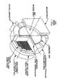
- FIG. 1 is an isometric view of a prior art Active Mirror Amplifier (AMA) for high-average power;
- AMA Active Mirror Amplifier
- FIG. 2 is an isometric view of a prior art laser diode illustrating the divergence of a beamlet produced thereby;
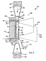
- FIG. 3 is a side cross-sectional view of an active mirror amplifier module in accordance with a preferred embodiment of the present invention.
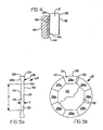
- FIG. 4 is a highly enlarged view of portion 4 of the amplifier in FIG. 3 ;
- FIGS. 5a and 5b are side cross-sectional and front views, respectively, of the composite gain medium assembly
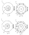
- FIGS. 6a-6d are front views of several alternate variants of the composite gain medium assembly
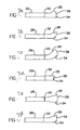
- FIGS. 7a-7f are cross-sectional views of several alternative forms of perimetral optical material which can be practiced with the present invention.
- FIG. 8 is a front view of the active mirror amplifier module of the present invention.
- FIGS. 9a and 9b are graphs illustrating how the radial variation of small-signal gain is affected by choices of diode divergence and diode distance from the axial center of the laser gain medium;
- FIG. 10 is a cross-sectional view of an alternative preferred embodiment of the active mirror amplifier module of the present invention which is especially suitable for tight packaging;
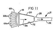
- FIG. 11 is an edge view illustrating the stacking of a plurality of laser diode arrays of pump source for improved delivery of optical pump radiation into the composite gain medium;
- FIG 12 is a side view of an alternative preferred embodiment of the present invention that does not incorporate a substrate with cooling channels;
- FIG 13 is a front view of the laser module of Figure 12 ;
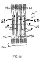
- FIG 14 is a cross-sectional view of a plurality of laser gain mediums ganged in parallel in a bank and forming flow channels therebetween;
- FIG 15 is a cross-sectional view of a plurality of laser gain mediums ganged in parallel in a bank and having spacers therebetween to form narrow flow channels;
- FIG 16 is a cross-sectional view of two amplifier bank arranges to reduce thermal distortion to the laser beam
- FIG 17 is a cross-sectional view of an amplifier bank with counterflowing coolant flows
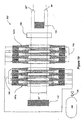
- FIG. 18 is a cross-sectional view of a laser device with a closed coolant loop
- FIG 19 is a cross-sectional view of a laser device with an open coolant loop
- FIG 20 is a cross-sectional view of an amplifier bank with sequenced excitation of optical pump sources
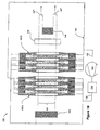
- FIG 21 is a cross-sectional view of an amplifier bank with repositionable optical pump sources.
- FIGs 21 a and 21 b show an amplifier bank.
- Laser gain medium refers to an optical material having a host lattice doped with suitable ions, which in the present invention are pumped to a laser transition.
- the preferred host lattice materials are yttrium aluminum garnet (YAG), gadolinium gallium garnet (GGG), gadolinium scandium gallium garnet (GSGG), lithium yttrium fluoride (YLF), yttrium vanadate, phosphate laser glass, silicate laser glass, athermal glass, sapphire, and transparent polycrystalline ceramic materials.
- YAG yttrium aluminum garnet
- GGG gadolinium gallium garnet
- GSGG gadolinium scandium gallium garnet
- YLF lithium yttrium fluoride
- yttrium vanadate phosphate laser glass, silicate laser glass, athermal glass, sapphire
- Example of a suitable ceramic host material is polycrystalline YAG available from Baikowski International Corporation.
- Suitable dopants for this lasing medium include Ti, Cu, Co, Ni, Cr, Ce, Pr, Nd, Sm, Eu, Gd, Tb, Dy, Ho, Er, Tm, and Yb.
- the optical pump source is selected based on the absorption characteristics of the selected laser gain medium.
- semiconductor diode lasers are used for the optical pump source.
- InGaAs diodes are preferred for pumping of Yb.sup.3+ ions.
- Period optical medium refers to an optical material which is preferably substantially free of substances that can significantly absorb optical pump radiation.
- the perimetral medium is of the same host material as the laser gain medium but it is not doped.
- perimetral optical medium may be doped with ions which absorb optical radiation at one or more wavelengths of the laser gain transition, but are not pumped to a population inversion. Such ions are intended for absorbing ASE photons and reducing feedback to parasitic oscillations in the laser gain medium.
- the perimetral optical medium can be doped with either divalent samarium or divalent cobalt ions, each of which exhibits strong absorption around 1.06 micrometer wavelength and relatively low absorption at around 808 nanometer and 885 nanometer wavelengths of optical pump sources.
- the perimetral optical medium may be bonded to selected surfaces of the laser gain medium by a fusion bond, or diffusion bond, or other suitable means. Such bond should be mechanically strong, thermally conductive, and highly transparent at the laser wavelength as well as at pump wavelengths.
- the refractive index of the updoped optical medium and the bond are preferably closely matched to that of the laser gain medium.
- a suitable bond can be produced by fusion bonding, diffusion bonding, or optical contacting followed by heat treatment.
- a fusion or diffusion bond may be produced, for example, by growing a perimetral crystal onto a doped crystal boule or, in the case of glass, by casting perimetral material around the peri meter of a doped core.
- a method for optical contacting followed by heat treatment is, for example, disclosed by Meissner in U.S. Patent Nos. 5,441,803 , 5,563,899 and 5,846,638 and is commercially available from Onyx Optics in Dublin, Calif.
- Another method suitable for glass involves casting and fusion bonding doped, undoped, or differently doped sections is available from Kigre Inc., Hilton Island, SC.
- Yet another method suitable for construction of composite polycrystalline materials is available from Baikowski International Corp. of Charlotte, N.C.
- the module 10 generally comprises a composite gain medium assembly 12, a substrate 46, optical pump sources 68, lenses 18, and tapered hollow ducts 20.
- the composite gain medium assembly 12 and the substrate 46 form an active mirror assembly 21.
- the composite gain medium assembly 12 has two planar, mutually parallel surfaces, a front surface 22 and a back surface 24, both being ground flat and polished to optical quality.
- the shape of the composite gain medium assembly 12 may vary widely but in one preferred form comprises an octogonal disk with a transverse dimension "D" several times greater than its thickness "T", as indicated in FIG. 5a .
- composite gain medium assembly 12 may have a thickness ranging approximately from 1 millimeter to 10 millimeters and transverse dimensions ranging from about 10 millimeters to 300 millimeters.
- the composite gain medium assembly 12 could just as readily be formed in other various shapes such as (but not limited to) polygonal, circular or elliptical shapes if desired.
- disk is used herein to reference this component, it will be appreciated that the composite gain medium assembly 12 may take other forms which might not be viewed, strictly speaking, as a "disk”.
- the composite gain medium assembly 12 comprises a laser gain medium 26 and eight segments 28a of perimetral optical material 28.
- the material of the laser gain medium disk 26 comprises a suitable solid-state laser gain medium such as, but not limited to, neodymium-doped yttrium-aluminum garnet (Nd:YAG), erbium-doped yttrium aluminum garnet (Er:YAG), ytterbium doped-yttrium aluminum garnet (Yb:YAG), neodymium gadolinium gallium garnet (Nd:GGG), ytterbium-doped gadolinium gallium garnet (Yb:GGG), neodymium-doped glass (Nd:Glass), erbium-doped glass (Er:Glass), ytterbium-doped glass (Yb:Glass), or other suitable laser SSL material.
- Nd:YAG neodymium-doped ytt
- Garnets can be provided in a single crystal or polycrystalline form.
- the perimetral optical medium 28 is attached around the perimeter of the laser gain medium 26 via an optical bond 30.
- the perimetral optical medium 28 has preferably the same host medium used in the laser gain medium 26 but does not contain a significant quantity of the dopant laser ions present in the laser gain medium 26.
- the optical bond 30 must be highly transparent to the optical pump radiation and laser radiation and have good thermal conductivity. Preferred methods for constructing the bond 30 include the already mentioned fusion bond, diffusion bond, and the method of optical contacting followed by heat treatment. Adjacent segments of perimetral optical medium 28 do not necessarily need to be joined together. For example, FIG. 5b shows a gap 32 existing between adjacent perimetral optical media 28a.
- some or all of the segments of the perimetral medium can be jointed to produce an optically and mechanically monolithic unit.
- Surfaces 34 which receive optical pump radiation 36 ( FIG. 3 ), have a dielectric coating 38 that is antireflective at optical pump radiation wavelengths.
- the optical bond 30 plane and ( FIG. 5a ) can be machined at a slight angle of 1-5 degrees off normal from surface 22 to reduce the possibility of direct ASE feedback to parasitic oscillations.
- Alternate forms of the shape of the perimetral material 28 are shown in Figures 7a-7f .
- the back planar surface 24 has an optical coating 40 with high reflectivity at a laser wavelength.
- a coating can be dielectric or metallic, or a combination of several layers of metallic and dielectric coatings.
- the front surface 22 has an optical coating 42 that is antireflective at the laser wavelength.
- the coatings 40 and 42 can also be individually made reflective at the optical pump wavelength in addition to their already mentioned properties with respect to the laser wavelength.
- the back surface 24 is in contact with a surface 44 of a cooled, rigid substrate 46.
- the surface 44 contains an array of interconnected microchannels 48 extending generally over, but not beyond, the contact area between the flat portion of composite gain medium 12 and the substrate 46.
- the substrate 46 contains a heat exchanger 50 that is located below the surface 44 and not connected to the microchannels 48.
- Coolant 52 is provided to the heat exchanger 50 by an inlet header 54 and drained therefrom by the outlet header 56. Internal distribution of the coolant 52 inside the heat exchanger 50 is such so as to provide a uniform cooling effect over a large part of the back surface 24 of the composite gain medium assembly 12.
- Suitable coolants may include liquids such as water, alcohol, members from the Freon.RTM. family, and liquid nitrogen.
- Coolant fluid connections to the inlet header 54 and the outlet header 56 can be provided by pressure-balanced, axially-movable fluid transfer tubes such as disclosed by Eitel in U.S. Pat. No.
- Such fluid transfer tubes isolate hydraulic pressure loads from the substrate 46 and coolant supply so that alignment of substrate 46 will not be affected.
- the fluid transfer tubes balance the hydraulic forces caused by the coolant pressure so that the substrate will not have any significant load placed upon it to interfere with its operation.
- such fluid transfer tubes permit small axial and lateral adjustments of substrate 46 such as may be required to optically align the laser gain medium 12 without affecting the operation of the fluid transfer tubes or placing forces on the substrate from the tubes.
- the cooled substrate 46 is made of a material with good thermal conductivity, preferably copper, tungsten, molybdenum, sapphire, silicon carbide, silicon, but other materials with good thermal conductivity and suitable for microchannel and heat exchanger fabrication can be used.
- the material of the substrate 46 can also be chosen to have a coefficient of thermal expansion close to that of the laser gain medium 26.
- Surface 44 of substrate 46 is machined to optical flatness except for penetrations created by the microchannels 48.
- Typical dimensions for the microchannels 48 include a width of about 0.005 inch to 0.040 inch (0.13 mm-1 mm) and a cross sectional area of about 0.000025 inch.sup.2-0.0016 inch.sup.2 (0.00016125 cm.sup.2-0.01032 cm.sup.2).
- Microchannels 48 preferably occupy about 50% of the contact area between surface 44 of substrate 46 and back surface 24 of composite gain medium 12.
- the microchannels 48 may also be formed in a variety of cross-sectional shapes, but preferably have a generally square cross-sectional shape.
- the thickness of the substrate 46 is chosen to provide mechanical rigidity necessary to ensure that the surface 44 remains optically flat under operational conditions.
- optically flat surfaces When optically flat surfaces are brought into contact, they may become bonded even without bonding agents. Such bonds can be attributed to Van der Vaals forces of attraction acting at opposing contact points and surfaces. Such bonding remains stable as long as the components of the composite are not subjected to temperature gradients that cause non-uniform thermal expansion, and resultant stress to overcome this bond strength. However, the bond may also be broken by inserting a strong thin object, for example a razor blade, between the optically contacted surfaces. De-bonding also results when liquids diffuse into the interface from the edge which constitutes the bond line.
- a positive contact between the back surface 24 of composite gain medium assembly 12 and surface 44 of the substrate 46 is maintained by a pressure differential between the higher pressure of the atmosphere 58 surrounding the amplifier module 10 and the lower pressure inside the microchannels 48.
- the microchannels 48 can be filled with either liquid (including liquid metals) or gas and are maintained at a pressure substantially lower than that of the atmosphere 58.
- One benefit of using liquid to fill the microchannels 48 is enhanced heat transfer due to increased thermal conductivity.
- the required pressure differential to maintain the surfaces 24 and 44 in contact over large portions of their areas is typically several tens of PSI.
- Such a continuous contact ensures that the back surface 24 will remain optically flat even when composite gain medium assembly 12 experiences significant thermal load.
- the continuous contact between surface 24 and surface 44 further facilitates the conductive transfer of heat from the gain medium assembly 12 to substrate 46.
- the su bstrate 46 may be further installed in an optical mount 60 to facilitate easy positioning and alignment.
- the atmosphere 58 can be further sealed from the microchannels 48 by an elastomeric seal 62 between the perimeter of the contact surface of composite gain medium assembly 12 and the surface 44.
- Seal 62 may also hold the composite gain medium assembly 12 to the substrate 46 in the absence of a pressure differential, such as during non-lasing conditions.
- Suitable materials for the elastomeric seal 62 include RTV.RTM. silicon rubber.
- Other forms of compliant seals such as an O-ring may also be used.
- Thermal dSSDLge to the seal 62 potentially caused by a misalignment of incident laser beam 64 is prevented by a collimator 66, which preferably absorbs laser radiation incident on the edge of the laser gain medium 26.
- the collimator 66 may incorporate suitable cooling means to dissipate absorbed heat.
- Seal 62 is preferably protected from optical pump radiation 36 by extending the high-reflectivity optical coating 40 to cover at least that portion of the perimetral optical medium 28 which is in contact with the seal 62.
- optical pump source 68 which preferably comprises an array of laser diodes, produces and directs optical pump radiation 36 into cylindrical lenses 18.
- the cylindrical lenses 18 focus the radiation into the converging hollow ducts 20.
- Internal surfaces 72 of the ducts 20 are made highly reflective to the optical pump radiation. Aided by reflections from surfaces 72, the optical pump radiation 36 gradually increases in intensity as it progresses towards the tapered end of the duct 20.
- Optical pump radiation 36 exiting the tapered end of the duct 20 enters the perimetral optical medium 28 and it is transmitted therethrough into the laser gain medium 26.
- Tapered portion 28b ( FIG.
- the perimetral optical medium 28 acts as a continuation of the duct 20 and further concentrates and channels pump radiation into the laser gain medium 26.
- pump radiation is channeled in a direction generally parallel to the surfaces 22 and 24 by multiple internal reflections therefrom.
- the optical pump radiation 36 is gradually absorbed.
- the material of laser gain medium 26 is doped with absorbing species so that 90% or more of incident pump radiation 36 is absorbed in the laser gain medium 26.
- Optical radiation 36 absorbed by dopant species in laser gain medium 26 pumps the dopant species to a laser transition. This allows the laser gain medium 26 to serve as an amplifier of coherent optical radiation.
- the incident laser beam 64 having approximately the same footprint as the aperture in the collimator 66, is directed into the laser gain medium 26 at a generally normal incidence through front surface 22 and is amplified until it reaches the reflective coating 40. On reflection from coating 40, the laser beam passes through the laser gain medium 26 again but in a generally reverse direction.
- the amplified laser beam 64' exits the laser gain medium 26 in a direction generally normal to the front surface 22.
- Waste heat dissipated in the laser gain medium 26 is conducted to the back surface 24, through the optical coating 40, and transferred to surface 44 of the substrate 46 from which it is conducted to the heat exchanger 50. Since the front surface 22 of the laser gain medium 26 is operating at above ambient temperature, it heats the surrounding atmosphere 58. This can lead to formation of pockets of warm atmosphere and/or eddy currents in the atmosphere 58. As a result, the laser beam 64 can experience a variation of its optical path and its optical phase fronts could be perturbed. This situation can be prevented by flowing a stream of gas from atmosphere 58 over the front surface 22, thereby sweeping the pockets of warm atmosphere from the front surface 22 and preventing the pockets from accumulating and/or forming eddy currents.
- a suitable stream of gas 72 can be generated, for example, by a gas jet 74 shown in Figure 3 , or by other suitable means.
- the perimetral optical material 28 serves several functions:
- Perimetral optical medium 28 receives concentrated optical radiation 36 from the tapered end of duct 20 and channels it into the laser gain medium 26.
- the perimetral optical material 28 serves as a continuation of the duct 20.
- Surface 34 of material 28 can be curved to provide an additional lensing effect.
- the perimetral optical material 28 is in good thermal contact with the laser gain medium 26 and provides a heat conduction path to substrate 46. This allows it to draw heat away from the perimeter of the laser gain medium 26 which reduces thermal stresses and distortions therein.
- the perimetral optical medium 28 is preferably chosen to have an index of refraction closely matching that of laser gain medium 26. This allows ASE rays to cross the boundary between the two materials without significant refection.
- the shape of the perimetral optical medium 28 can be chosen so as to trap such ASE rays and/or channel them outside the composite gain medium assembly 12. By so reducing the feedback of ASE rays from the boundary of composite gain medium assembly 12, the feedback mechanism for parasitic oscillations is largely eliminated and oscillations can be suppressed.
- the perimetral optical medium 28 can be doped with ions that are absorbing at a laser gain wavelength but not significantly absorbing at optical pump wavelengths. Absorption of ASE rays in the perimetral optical medium 28 accelerates their decay.
- FIGS. 6a-6d show examples of alternate constructions of the composite gain medium 12.
- FIGS. 6c and 6d use two layers of perimetral optical media 28 and 28'. This allows each of the perimetral optical media 28 and 28' to be either undoped or doped differently with ASE absorbing ions.
- FIG. 8 is a front view of the amplifier module 10 showing optical pump source 68, lenses 18, and tapered hollow ducts 20 providing optical pump radiation 36 into the composite gain medium assembly 12 with octagonal doped laser gain medium 26.
- the circular arrangement of pump source 68 is produced by placing laser diode arrays 68a so as to generally point toward the center of laser gain medium 26. This pump source arrangement makes it possible to achieve laser gain that is uniform across large portions of the laser gain medium 26. Beamlets produced by individual laser diode elements (as for example shown in FIG. 2 ) in optical pump source 68 overlap inside the laser gain medium 26 and their intensities are summed.
- the resulting intensity of overlapped beamlets depends on the power output and beamlet divergencies of individual diode elements of each diode array 68a, the distance of the diode elements from the center of the laser gain medium 26, parameters of the lens 18 and the duct 20, the doping density of laser gain medium 26 and the radial position (with respect to the center of laser gain medium26) of the location where the intensity is measured.
- a uniform gain profile is produced in the laser gain medium 26 across the aperture defined by the collimator 66. This is accomplished by choosing an appropriate combination of beamlet divergencies of individual diode elements in optical source 68, by the distance of the diode elements of each diode array 68a from the center of the laser gain medium 26, by the parameters of the lens 18 and the duct 20, and by the doping density of laser gain medium 26.
- Suitable methods for producing a tailored gain profile in a side-pumped SSDL are disclosed in Applicant's US Patent Application Serial Number 10/441,373 filed on May 19, 2003 , which is hereby incorporated herein by reference.
- Figures 9a and 9b show examples of how the radial variation of small-signal gain is affected by choices of divergence of optical pump sources 68 (in the plane parallel to surface 22) and the distance of optical pump sources 68 from the center of laser gain medium 26.
- the present invention can also be used to provide nearly uniform gain when the medium is saturated. For example, when the invention is used to amplify laser beams with higher intensity in the central portion of the beam, the gain saturation effects near the beam center can be countered by appropriately increasing the pumping intensity (and hence small-signal gain) near the center of laser gain medium 26.
- an alternate version of the first preferred embodiment of the SSDL of the present invention is suitable for operation at increased optical power density.
- the internal heat exchanger 50 inside substrate 46 can be omitted and the coolant 52 is provided to microchannels 48 and allowed to directly wet large portions of the back surface 24 of the composite gain medium assembly 12.
- heat generated in the laser gain medium 26 is conducted through the surface 24 and the optical coating 40 directly into the coolant 52.
- Coolant 52 is introduced into the microchannels 48 to provide a uniform cooling effect over a large portion of the back surface 24 of the gain medium assembly 12.
- the pressure of coolant 52 is maintained lower than the pressure of atmosphere 58 to assure attachment of composite gain medium assembly 12 to substrate 46 as already explained above.
- FIG. 10 shows an active mirror amplifier module 10' wherein the optical pump sources 68 and the tapered hollow ducts 20 are mounted in closer proximity to the substrate 46 and optical mount 60.
- the composite gain medium assembly 12' incorporates perimetral optical medium 28' having a surface 70' at approximately a 45 degree angle with respect to the surface 24 ( FIG. 5a ) of the gain medium assembly 12'.
- the surface 70' has a coating 74 which is highly reflective at the optical pump radiation wavelengths.
- Surface 34' of the perimetral optical medium has a coating 76 which is antireflective at the optical pump radiation wavelengths.
- Optical pump radiation 36 is injected into the surface 34' and reflected from coating 74 into the laser gain medium 26.
- the efficiency of concentrating pump radiation in duct 20 can be further improved by stacking laser diode arrays 68a in the plane of pump source 68 to directly point toward the surface 34 of the composite laser gain medium assembly 12 as shown in FIG. 11 .
- This configuration of the pump source 68 also reduces the need for the lens 72 so that the lens can be omitted from the system.
- the invention can also be practiced with a solid material lensed duct such as disclosed by Beach et al. in U.S. Pat. No. 5,307,430 in lieu of the hollow duct 20.
- a solid material lensed duct can be more efficient for concentration of pump radiation.
- one drawback of the solid lensed duct in high-average power applications is that low thermal conductivity of the solid duct material (typically optical glass) makes it difficult to remove heat generated therein by pump radiation. If optical pump sources 68 of sufficient intensity are used, then the need for the concentrator duct 20 is eliminated.
- the invention can also be practiced with a transmissive laser gain medium disk (rather than reflective disk in AMA configuration) and without the substrate 46.
- FIG 12 there is shown a SSDL amplifier module 11 in accordance with a second preferred embodiment of the present invention.
- the module 11 generally comprises a composite gain medium assembly 12", optical pump sources 68, lenses 18, and tapered hollow ducts 20.
- the composite gain medium assembly 12" is essentially the same as the composite gain medium assembly 12, except that both surfaces 22 and 24 now have the optical coating 42 which is antireflective at a laser gain wavelength.
- the composite gain medium assembly 12" is preferably suspended by the perimetral optical medium 28, which is supported by optical mount 60'.
- the laser gain medium 26 is pumped to a laser transition by the optical pump sources 68 in the same manner as in the SSDL amplifier module 10. This allows the laser gain medium 26 to serve as an amplifier of coherent optical radiation.
- the incident laser beam 64 having approximately the same footprint as the aperture in the collimator 66, is directed into the laser gain medium 26 at a generally normal incidence through surface 24 and is amplified.
- the amplified laser beam 64' exits the laser gain medium 26 in a direction generally normal to the surface 22.
- the amplifier module 11 can be also practiced (i.e., positioned) at a Brewster angle with respect to the incident laser beam 64. In this case, the antireflection coating 42 on surfaces 22 and 24 can be omitted.
- Waste heat dissipated in the laser gain medium 26 is conducted to both surfaces 22 and 24, through the optical coating 42, and transferred to coolant 52 flowing generally parallel to the surfaces 22 and 24.
- the coolant 52 and its flow conditions should be chosen so as to permit a high heat transfer rate while avoiding perturbation to the optical phase front and scattering losses of the laser beams 64 and 64'.
- a preferred coolant is gaseous helium, although any other suitable coolant could be employed.
- nitrogen and helium flows at subsonic velocities have shown that heat transfer rates on the order of several watts/cm 2 can be achieved at subsonic flow conditions around Mach 0.2 (see for example S.B. Sutton et al., "Thermal Management in Gas Cooled Solid-State Disk Amplifiers," UCRL-JC-109280, which can be obtained from the technical library of the Lawrence Livermore National Laboratory.
- FIG. 13 is a front view of the amplifier module 11 showing optical pump sources 68, lenses 18, and tapered hollow ducts 20 providing optical pump radiation 36 into the composite laser gain medium assembly 12".
- the laser gain medium assembly 12" has circular doped laser gain medium 26 and octagonal perimetral edge 28.
- the octagonal arrangement of pump sources 68 is produced by placing one or more laser diode arrays 68a at each edge of the octagon so as to generally point toward the center of laser gain medium 26. This pump source arrangement makes it possible to achieve laser gain that is uniform across large portions of the laser gain medium 26 (see, for example, J.
- diode sources 68 and the perimeter of perimetral medium 28 could have other polygonal shapes, or be generally circular as shown for example in Figure 7 , and as noted above.
- a laser gain medium 26 with a polygonal perimeter can be practiced with a perimetral medium of a different shape (namely circular or elliptical) and conversely, or they can both have the same general shape.
- An alternate configuration of the SSDL amplifier 11 that uses higher intensity optical pump sources 68 can be practiced without the lens 18 and hollow duct 20.
- the SSDL amplifiers 10, 10' and 11 of the subject invention can be operated in a thermally continuous mode where the heat deposited into the laser gain medium 26 is removed in real time by coolant 52, or in a semi-continuous heat capacity mode where the laser gain medium 26 is allowed to gradually warm up to a predetermined limiting temperature.
- a solid-state laser operating in the "heat capacity laser” has been disclosed by Albrecht et al. in U.S. Pat. No. 5,526,372 .
- the laser gain medium 26 is cooled to an initial operating temperature.
- the laser gain medium 26 gradually warms up until it reaches its final operating temperature.
- the laser operation is suspended and the laser gain medium 26 is allowed to cool again to its initial operating temperature by transferring its stored heat to the coolant 52. After reaching this temperature, the process can be repeated. In this fashion, the laser can be operated in a semi-continuous fashion.
- the length of the laser cycle depends on the rate at which waste heat is deposited into the laser gain medium, the weight and specific heat (cp) of the laser gain medium and the allowable temperature rise.
- the length of the cooling cycle depends on the effectiveness of the cooling applied to the laser gain medium.
- SSDL modules 10, 10', and 11 or variants thereof can be used to construct laser amplifiers as well as laser oscillators. In either case, multiple SSDL modules are required to obtain required laser gain and laser power.
- Boeing owned U.S. Patent No. 6,603,793 discloses how SSDL modules in a AMA configuration (e.g., 10 and 10') can be arranged in a laser device.
- Figure 14 shows how SSDL modules 11 using transmissive composite gain medium assemblies 12" can be used to construct an amplifier bank 100.
- Several composite gain media 12" and associated optical pump sources 68 are placed adjacent to each other thereby forming between them passages (flow channels) 90 for flowing a cooling medium 52.
- the spacing between adjacent composite gain medium assemblies 12" and the width of flow channels 90 are approximately of the same magnitude as the thickness of each gain medium assembly 12".
- the size of such spacing depends on the design of the perimetral optical medium 28 and the optical pump source 68. In practice, such spacing preferably ranges from about 1 to 10 millimeters.
- the cooling medium in adjacent channels 90 can be flowed in the same or in opposite directions. Although the latter approach somewhat complicates the coolant medium delivery and recovery routing, it greatly reduces the transverse component in temperature gradient inside the gain medium 26 and makes it much easier to maintain alignment and beam quality of the laser beam 64.
- Figure 15 shows an SSDL amplifier bank 100' that reduces flow requirements for coolant medium 52.
- the spacing of adjacent composite gain medium assemblies 12" is approximately the same as in the configuration shown Figure 14 .
- spacers 92, mounted on holders 80 are installed in the gap between adjacent composite gain medium assemblies 12", thereby reducing the width of the flow channel for coolant medium 52.
- the preferred width of the coolant channels 90' is approximately in the range from 0.5 to 2.0 millimeters. The resulting reduction in coolant medium flow rates allows using a smaller coolant flow system including smaller sizes of the pumps, storage tanks, and piping.
- Spacers 92 are each preferably of the same thickness and made of the same material as the host material for the gain medium 26 and do not contain ions for lasing at the laser wavelength of the gain medium 26.
- the spacers 92 can be made of a thermal optical material that offers low thermo-optic distortion.
- spacers 92 each preferably have an anti-reflective coating on both large faces to avoid excessive loss of power in laser beam 64 by reflection.
- spacers 90 provide additional reservoirs for heat storage. Efficient transfer of heat from each composite laser gain medium assembly 12" to its associated spacer 90 is made possible by flowing the coolant 52 through a narrow passage 90. Heat storage capacity of spacers 90 can be increased by appropriately increasing their thickness.
- Coolant 52 flowing in passage 90 removes heat from the composite laser gain medium assembly 12" and gradually warms up.
- down stream portion 124 of the composite laser gain medium assembly 12" is considerably higher in temperature than the upstream portion 122. Temperature affects both the index of refraction and thermal expansion of the laser gain medium 26, each in turn affecting the length of optical path through the medium.
- coolant 52 in adjacent gaps 90 flows in the same direction.
- the optical path of the rays near the edge 164a of laser beam 64 is significantly different than the optical path of the rays near the edge 164b. This causes an optical path difference (OPD) and perturbation to the optical phase fronts of laser beam 64.
- OPD optical path difference
- Figure 16 shows an arrangement of two amplifier modules 100'a and 100'b having their respective coolants 52 and 52' showing in opposite directions. This arrangement significantly reduces thermal distortion caused by coolant temperature rise. Another approach for mitigation of the OPD resulting from coolant temperature rise is to counter-flow the coolant.
- Figure 17 shows an amplifier module 100" where the coolant in adjacent passages 90 is flowed in opposite directions.
- Another type of perturbation to the temperature profile in the laser gain medium 26 is caused by non-uniform deposition of optical pump radiation 36.
- Computer simulations and laboratory testing performed by the applicant indicates that such perturbations acquire spatial distribution patterns that are related to the arrangement of optical pump sources 68 around the perimeter of composite gain medium. For example, if optical pump sources 68 are arranged in octagonal configuration such as shown in Figure 14 , the pump density distribution in the laser gain medium 26 can be expected to have at least slight spatial non-uniformities that form a generally octagonal pattern.
- the OPD caused by this effect in a single composite gain medium assembly 12" is typically a small fraction of laser wavelength, contributions from multiple disks can sum up to a very significant distortion of optical phasefront.
- Cumulative phase error can be greatly reduced by reducing the correlation of individual error contributions.
- errors in individual composite gain medium assemblies 12" operated with optical radiation sources 68 arranged in polygonal arrays can be at least partially de-correlated by slightly rotating (clocking) about the laser beam 64 each polygonal array with respect to its neighbor.
- clocking about the laser beam 64 each polygonal array with respect to its neighbor.
- each array should be clocked by preferably about 15 degrees with respect to each other.
- the first array is clocked by 0 degrees, second array by 15 degrees, and the third array by 30 degrees.
- the correction of a distorted phase front in laser beam 64' can also be achieved by passing the distorted laser beam through a phase corrector 174.
- the phase corrector 174 is an optical element with one or more surfaces machined to reverse the effects of OPD in amplifier module 100.
- Coolant 52 for operation of the amplifier modules 11, 100, 100' and 100" can be provided by a closed or open coolant supply loop. If the coolant flow passage 90 is made sufficiently narrow (preferably 0.5 to 1.0 millimeters) the coolant flow rate required to operate the amplifier module is rather modest. For example, a flow of helium at Mach 0.2 used for cooling composite gain medium 12' with a 10-cm diameter laser gain medium 26 and a 0.5-millimeter wide flow passage can extract heat from the laser gain medium at a rate of around 5 Watts per centimeter square. This translates to a flow of 14 standard liters per second per flow passage.
- FIG 18 shows a laser device 200 comprising amplifier modules 100'a and 100'b, end mirror 142 and outcoupling mirror 144 forming an unstable resonator, static phase corrector 148, and coolant loop 146.
- Laser beam 64" oscillates between the mirrors 142 and 144, and portion 64'" is outcoupled.
- the coolant flow loop 146 further comprises a compressor 152, heat exchanger 154 and interconnecting lines.
- Warm coolant 52 exhausted from the amplifier modules 100'a and 100'b is collected into return line 156 which feeds the compressor 152.
- the compressor 152 receives the coolant 52, compresses it and discharges compressed coolant into heat exchanger 154.
- the heat exchanger 154 thermally conditions the coolant to the appropriate temperature and conveys it into feed line 158 that delivers it to amplifier modules 100a and 100b.
- FIG 19 shows a laser device 200' which is similar to laser device 200 except that the coolant loop 162 is open.
- the coolant loop 162 comprises a gas storage tank 164, control valve 166, and interconnecting lines.
- coolant 52 is released from the storage tank 164 by control valve 166 and flowed into the feed line 168 that delivers it to amplifier modules 100'a and 100'b.
- Coolant 52 exiting from the amplifier modules 100'a and 100'b forms an exhaust flow 168 which is vented to atmosphere.
- Figure 20 shows an SSDL amplifier bank 100'" that reduces the time-averaged heat load to laser gain medium assemblies 12".
- the laser gain medium assemblies 12"a through 12" are respectively pumped by optical radiation sources 68a through 68h sequentially rather than all at the same time. For example, first the optical pump radiation source 68a is energized to pump laser gain medium assembly 12"a. Subsequently the optical pump radiation source 68a is turned off and, possibly after a pause, optical pump radiation source 68b is energized to pump laser gain medium assembly 12"b, and so on, and the process is repeated. Alternately, laser gain medium assemblies 12" can be pumped in groups.
- laser gain medium assemblies 12"a, 12"c, 12"e, and 12"g are pumped as one group first and then turned off followed by pumping laser gain medium assemblies 12"b, 12"d, 12"f, and 12"h. Since coolant 52 is flowed preferably in continuous fashion, surfaces of all of the laser gain medium assemblies 12"a through 12" are utilized for heat removal.
- Figures 21a and 21b show an SSDL amplifier bank 100 iv that reduces the time-averaged heat load to laser gain medium assemblies 12". Similar to SSDL amplifier bank 100'" the optical pump in SSDL amplifier bank 100 iv is also provided to selected laser gain medium assemblies on alternating basis. However, in SSDL amplifier bank 100 iv the selection is accomplished by a combination of mechanical and electrical means rather than solely by electrical excitation means. For example, in Figure 21a optical pump radiation sources 68a, 68c, 68e, and 68g are positioned and energized to pump laser gain medium assembly 12"a, 12"c, 12"e, and 12"g.
- the optical pump radiation sources 68a, 68c, 68e, and 68g are re-positioned and energized to pump laser gain medium assembly 12"b, 12"d, 12"f, and 12"h. After predetermined pump period in this position the cycle may be repeated.
- Alternate means for switching optical pump radiation to selected laser gain medium assemblies is by optical switching that can used reflecting and/or refracting components. Such components can be activated electrically and/or mechanically.
Landscapes
- Physics & Mathematics (AREA)
- Electromagnetism (AREA)
- Engineering & Computer Science (AREA)
- Plasma & Fusion (AREA)
- Optics & Photonics (AREA)
- Chemical & Material Sciences (AREA)
- Crystallography & Structural Chemistry (AREA)
- Lasers (AREA)
Claims (42)
- Batterie d'amplificateurs laser (100') présentant une pluralité de modules de laser à l'état solide pour une amplification du rayonnement laser, lesdits modules de laser étant placés adjacents les uns par rapport aux autres et chacun desdits modules de laser comportant
un support de gain de laser (26) ayant une paire de surfaces généralement parallèles (22, 24) et prenant la forme d'un disque, ladite paire de surfaces (22, 24) étant adaptée pour au moins transmettre et/ou recevoir un rayonnement laser;
au moins un support optique périphérique (28) agencé de manière adjacente à une arête périphérique dudit support de gain de laser (26) et en communication optique avec ledit support de gain de laser (26); et
une source (68) de rayonnement de pompe optique (36) pour diriger un rayonnement de pompe optique dans ledit support optique périphérique (28) de manière généralement parallèle auxdites surfaces généralement parallèles (22, 24), ledit support optique périphérique (28) étant utilisé pour transporter ledit rayonnement de pompe optique dans ledit support de gain de laser (26) et pour pomper ledit support de gain de laser (26) à un niveau de transition de laser;
caractérisée en ce que
les modules de laser forment entre eux des canaux de flux (90) pour faire circuler un fluide de refroidissement (52). - Batterie d'amplificateurs laser selon la revendication 1, dans laquelle
ladite paire de surfaces (22, 24) a une première dimension, lesdites surfaces de ladite paire de surface (22, 24) étant en outre opposées l'une à l'autre et étant séparées par une surface d'arête périphérique dudit support de gain de laser (26), ledit support de gain de laser (26) ayant une épaisseur représentant une seconde dimension qui est sensiblement plus petite que ladite première dimension, et
ledit au moins un support optique périphérique (28) est attaché à ladite surface d'arête périphérique et est en communication mécanique, thermique et optique. - Batterie d'amplificateurs laser selon la revendication 2, dans laquelle ladite paire de surfaces (22, 24) dudit support de gain de laser (26) est généralement à un angle de Brewster relativement à un axe de propagation dudit rayonnement laser.
- Batterie d'amplificateurs laser selon la revendication 2, dans laquelle ladite paire de surfaces (22, 24) dudit support de gain de laser (26) est généralement perpendiculaire relativement à un axe de propagation dudit rayonnement laser, et présente en outre des revêtements optiques pour fournir une réflectivité réduite à une longueur d'onde d'émission de laser dudit support de gain de laser (26).
- Batterie d'amplificateurs laser selon la revendication 2, dans laquelle au moins l'une de ladite paire de surfaces (22, 24) est refroidie par un fluide de refroidissement (52) circulant généralement dans une direction parallèle auxdites surfaces (22, 24).
- Batterie d'amplificateurs laser selon la revendication 5, dans laquelle le fluide de refroidissement (52) comporte une forme gazeuse.
- Batterie d'amplificateurs laser selon la revendication 5, dans laquelle ledit fluide de refroidissement (52) est recyclé entre ledit module et un échangeur thermique (50) pour supprimer de la chaleur dudit module de laser.
- Batterie d'amplificateurs laser selon la revendication 6, dans laquelle ladite forme gazeuse est stockée dans un réservoir sous pression et, à partir de celui-ci, envoyée d'une manière commandée à travers ledit module de laser et éliminée dans l'atmosphère.
- Batterie d'amplificateurs laser selon la revendication 2, dans laquelle le support optique périphérique (28) est dopé avec un matériau absorbant de manière importante le rayonnement optique à la longueur d'onde de laser dudit support de gain de laser (26) et ayant généralement une absorption faible à la longueur d'onde dudit rayonnement de pompe optique (36).
- Batterie d'amplificateurs laser selon la revendication 2, dans laquelle ledit support de gain de laser (26) comporte des ions néodyme trivalents et ledit support optique périphérique (28) comporte des ions divalents choisis dans le groupe comportant du samarium et du cobalt.
- Batterie d'amplificateurs laser selon la revendication 2, dans laquelle ledit support de gain de laser (26) comporte des ions erbium trivalents et ledit support optique périphérique (28) comporte des ions cobalt divalents.
- Batterie d'amplificateurs laser selon la revendication 2, dans laquelle ladite arête périphérique dudit support de gain de laser (26) a une forme sélectionnée dans le groupe de formes circulaires, elliptiques, rectangulaires, pentagonales, hexagonales, heptagonales, octogonales, et polygonales.
- Batterie d'amplificateurs laser selon la revendication 2, dans laquelle ladite surface d'arête périphérique dudit support de gain de laser (26) comporte une pluralité de sections planaires; et
dans laquelle ledit support de gain de laser (26) comporte une pluralité correspondante de sections de support optique périphérique (28) qui sont attachées fixement audites sections planaires via une liaison qui est transparente aux longueurs d'onde dudit rayonnement de pompe optique (36) et à une longueur d'onde d'émission de laser dudit support de gain de laser (26). - Batterie d'amplificateurs laser selon la revendication 2, dans laquelle ledit support optique périphérique (28) est attaché fixement à ladite arête périphérique via une liaison (30) qui est transparente à des longueurs d'onde dudit rayonnement de pompe optique (36) et à une longueur d'onde d'émission de laser dudit support de gain de laser (26).
- Batterie d'amplificateurs laser selon la revendication 2, dans laquelle ledit support de gain de laser (26) comporte un réseau hôte, et dans laquelle au moins l'un dudit réseau hôte et dudit support optique périphérique (28) est sélectionné dans le groupe comportant du:grenat d'yttrium-aluminium (YAG), grenat de gadolinium-gallium (GGG), grenat de scandium gallium gadolinium (GSGG), YAG polycristallin, GGG polycristallin, fluorure d'yttrium-lithium (YLF), vanadate d'yttrium, tungstate de potassium et gadolinium (KGd(WO4)2), tungstate de potassium et yttrium (KY(WO4)2), verre aux phosphates, verre athermique, verre de silice, céramique transparente, et saphir.
- Batterie d'amplificateurs laser selon la revendication 15, dans laquelle le réseau hôte est dopé avec au moins un matériau choisi dans le groupe comportant: Ti, Cu, Co, Ni, Cr, Ce, Pr, Nd, Sm, Eu, Gd, Tb, Dy, Ho, Er, Tm et Yb.
- Batterie d'amplificateurs laser selon la revendication 2, dans laquelle ledit support de gain de laser (26) comporte un ion Yb trivalent.
- Batterie d'amplificateurs laser selon la revendication 17, dans laquelle ledit ion Yb trivalent est dopé dans le réseau hôte avec un matériau choisi dans le groupe comportant: YAG, GGG, YAG polycristallin, GGG polycristallin, verre aux phosphates, verre athermique et céramique transparente.
- Batterie d'amplificateurs laser selon la revendication 17, dans laquelle le rayonnement de pompe optique (36) est délivré à la longueur d'onde correspondant généralement à une raie spectrale zéro phonon de l'ion Yb trivalent.
- Batterie d'amplificateurs laser selon la revendication 2, dans laquelle ledit support de gain de laser (26) comporte un ion Nd trivalent.
- Batterie d'amplificateurs laser selon la revendication 20, dans laquelle ledit ion Nd trivalent est dopé dans le réseau hôte avec un matériau choisi dans le groupe comportant: YAG, GGG, YAG polycristallin, GGG polycristallin, verre aux phosphates, verre athermique et céramique transparente.
- Batterie d'amplificateurs laser selon la revendication 2, dans laquelle ladite source (68) de rayonnement de pompe optique (36) comporte un réseau de diodes laser.
- Batterie d'amplificateurs laser selon la revendication 20, dans laquelle le rayonnement de pompe optique (36) est délivré à la longueur d'onde d'une caractéristique d'absorption de l'ion Nd trivalent à environ 880 nanomètres correspondant à un dépôt d'énergie direct dans un niveau de laser supérieur.
- Batterie d'amplificateurs laser selon la revendication 2, dans laquelle la source de pompe optique (68) comporte au moins un réseau de diodes laser.
- Batterie d'amplificateurs laser selon la revendication 2, dans laquelle ladite source de pompe optique (68) comporte une pluralité de microlentilles (18).
- Batterie d'amplificateurs laser selon la revendication 2, comportant en outre une pluralité desdites sources de pompe optique (68), et dans laquelle lesdites sources de pompe optique sont agencées dans un motif généralement plus grand et de la même forme que le périmètre dudit support de gain de laser (26) et avec des sources de pompe optique individuelles généralement orientées vers ledit support de gain de laser (26).
- Batterie d'amplificateurs laser selon la revendication 2, comportant en outre au moins un conduit conique (20) pour la concentration dudit rayonnement de pompe optique (36), ledit conduit conique étant interposé entre ledit support optique périphérique (28) et une source de rayonnement optique afin de diriger le rayonnement de pompe optique (36) vers ledit support optique périphérique (28) .
- Batterie d'amplificateurs laser selon la revendication 27, dans laquelle ledit conduit conique (20) comporte un matériau optique solide.
- Batterie d'amplificateurs laser selon la revendication 27, dans laquelle ledit conduit conique (20) comporte un conduit creux.
- Batterie d'amplificateurs laser selon la revendication 27, dans laquelle ledit conduit creux (20) est rempli d'un liquide hautement transparent à la longueur d'onde dudit rayonnement de pompe optique (36).
- Batterie d'amplificateurs laser selon la revendication 2, dans laquelle ledit support optique périphérique (28) comporte au moins une partie conique pour la concentration dudit rayonnement de pompe optique (36).
- Batterie d'amplificateurs laser selon la revendication 2, dans laquelle ledit support optique périphérique (28) comporte au moins une surface courbe pour délivrer un effet de lentille pour la concentration dudit rayonnement de pompe optique (36).
- Batterie d'amplificateurs laser selon la revendication 2, dans laquelle ledit support de gain de laser (26) est suspendu par ledit support optique périphérique (28).
- Batterie d'amplificateurs laser selon la revendication 2, dans laquelle ledit support de gain de laser (26) est continuellement refroidi.
- Batterie d'amplificateurs laser selon la revendication 2, dans laquelle ledit support de gain de laser (26) est refroidi par un fluide de refroidissement circulant sur ladite paire de surfaces (22, 24).
- Batterie d'amplificateurs laser selon la revendication 35, dans laquelle ledit fluide de refroidissement (52) comporte une forme gazeuse.
- Batterie d'amplificateurs laser selon la revendication 1, dans laquelle des éléments d'écartement (92) sont insérés dans lesdits canaux de flux pour réduire la largeur de ces canaux, lesdits éléments d'écartement (92) étant transparents à la longueur d'onde de rayonnement laser.
- Batterie d'amplificateurs laser selon la revendication 1, dans laquelle ledit fluide de refroidissement (52) est envoyé de manière antiparallèle dans des canaux de flux adjacents.
- Batterie d'amplificateurs laser selon la revendication 1, dans laquelle ledit rayonnement de pompe optique (36) est alterné entre des groupes sélectionnés de supports de gain laser (26).
- Batterie d'amplificateurs laser selon la revendication 39, dans laquelle ledit rayonnement de pompe optique (36) est alterné entre lesdits groupes sélectionnés de supports de gain laser au moyen d'un procédé choisi dans le groupe comportant une excitation électrique, un positionnement mécanique, et une commutation optique.
- Batterie d'amplificateurs laser selon la revendication 1, dans laquelle lesdits supports de gain laser (26) sont positionnés de manière à y réduire la corrélation d'erreurs de trajet optique.
- Batterie d'amplificateurs laser selon la revendication 1, dans laquelle lesdites sources (68) de rayonnement de pompe optique (36) sont positionnées de manière à y réduire la corrélation d'erreurs de trajet optique.
Applications Claiming Priority (3)
| Application Number | Priority Date | Filing Date | Title |
|---|---|---|---|
| US10/662,023 US6999839B2 (en) | 2001-01-22 | 2003-09-12 | Side-pumped solid-state disk for high-average power |
| US10/862,887 US7200161B2 (en) | 2001-01-22 | 2004-06-07 | Side-pumped solid-state disk laser for high-average power |
| PCT/US2004/029723 WO2005029656A1 (fr) | 2003-09-12 | 2004-09-10 | Laser a disque a circuits integres a pompage lateral pour puissance moyenne elevee |
Publications (2)
| Publication Number | Publication Date |
|---|---|
| EP1668748A1 EP1668748A1 (fr) | 2006-06-14 |
| EP1668748B1 true EP1668748B1 (fr) | 2008-05-21 |
Family
ID=34381410
Family Applications (1)
| Application Number | Title | Priority Date | Filing Date |
|---|---|---|---|
| EP04783804A Expired - Lifetime EP1668748B1 (fr) | 2003-09-12 | 2004-09-10 | Laser à disque à l'état solide à pompage latéral de puissance moyenne élevée |
Country Status (5)
| Country | Link |
|---|---|
| US (1) | US7200161B2 (fr) |
| EP (1) | EP1668748B1 (fr) |
| AT (1) | ATE396526T1 (fr) |
| DE (1) | DE602004014001D1 (fr) |
| WO (1) | WO2005029656A1 (fr) |
Families Citing this family (38)
| Publication number | Priority date | Publication date | Assignee | Title |
|---|---|---|---|---|
| US7346091B2 (en) * | 2005-01-12 | 2008-03-18 | Raytheon Company | High energy solid-state laser with offset pump and extraction geometry |
| US7430230B2 (en) * | 2005-04-07 | 2008-09-30 | The Boeing Company | Tube solid-state laser |
| US7477674B2 (en) * | 2005-11-14 | 2009-01-13 | The Boeing Company | High-gain solid-state laser |
| JP2008010603A (ja) * | 2006-06-29 | 2008-01-17 | Ricoh Co Ltd | 半導体レーザ励起固体レーザ装置、光走査装置、画像形成装置及び表示装置 |
| US20080080584A1 (en) * | 2006-09-29 | 2008-04-03 | Usa Of America As Represented By The Administrator Of The National Aeronautics & Space Adm. | Solid-state laser gain module |
| FR2909806B1 (fr) * | 2006-12-12 | 2010-01-01 | Saint Louis Inst | Cristal et source laser a haute energie associe. |
| US7978746B2 (en) * | 2008-04-25 | 2011-07-12 | The Boeing Company | Unstable laser disk resonator |
| US7822091B2 (en) * | 2008-07-14 | 2010-10-26 | Lockheed Martin Corporation | Inverted composite slab sandwich laser gain medium |
| US7813405B2 (en) * | 2008-08-04 | 2010-10-12 | The Boeing Company | Unstable disk resonator |
| US8897326B2 (en) * | 2008-09-08 | 2014-11-25 | Ams Research Corporation | Pump energy wavelength stabilization |
| CN101572383B (zh) * | 2009-05-27 | 2010-11-10 | 华北电力大学(保定) | 具有光纤泵浦装置的固体激光器 |
| US8749880B2 (en) * | 2009-11-24 | 2014-06-10 | Applied Energetics | Off axis walk off multi-pass amplifiers |
| US8213471B2 (en) * | 2010-01-22 | 2012-07-03 | Integral Laser Solutions, Llc | Thin disk laser operations with unique thermal management |
| US8509281B2 (en) * | 2010-02-11 | 2013-08-13 | The Boeing Company | Disk laser |
| RU2439761C1 (ru) * | 2010-10-11 | 2012-01-10 | Федеральное государственное предприятие "Научно-исследовательский институт "Полюс" им. М.Ф. Стельмаха" | Активный элемент дискового лазера |
| FR2969401B1 (fr) | 2010-12-17 | 2013-01-18 | Thales Sa | Dispositif d'emission d'un faisceau laser anti lasage transverse et a refroidissement longitudinal |
| US9590388B2 (en) * | 2011-01-11 | 2017-03-07 | Northrop Grumman Systems Corp. | Microchannel cooler for a single laser diode emitter based system |
| FR2974251B1 (fr) * | 2011-04-18 | 2013-11-01 | Ecole Polytech | Dispositif pour la gestion thermique d'un élément optique et procédé de gestion thermique associe. |
| US9453914B2 (en) * | 2011-09-08 | 2016-09-27 | Continental Advanced Lidar Solutions Us, Inc. | Terrain mapping LADAR system |
| US8797512B2 (en) * | 2011-09-15 | 2014-08-05 | Advanced Scientific Concepts, Inc. | Automatic range corrected flash ladar camera |
| WO2014035525A2 (fr) | 2012-06-12 | 2014-03-06 | Integral Laser Solutions, Llc. | Refroidissement actif de dômes et radômes de missile chercheur à vitesse élevée |
| CN103779772B (zh) * | 2014-01-23 | 2016-06-01 | 中国航空工业集团公司北京航空制造工程研究所 | 采用复合泵浦耦合的激光器模块及固体激光器 |
| CN104051940B (zh) * | 2014-06-04 | 2017-02-15 | 上海交通大学 | 复合式激活反射镜结构激光放大器及放大注入脉冲的方法 |
| US9762018B2 (en) * | 2014-12-09 | 2017-09-12 | Raytheon Company | System and method for cooling a laser gain medium using an ultra-thin liquid thermal optical interface |
| US9899798B2 (en) | 2015-08-03 | 2018-02-20 | University Of Central Florida Research Foundation, Inc. | Apparatus and method for suppressing parasitic lasing and applications thereof |
| US9742142B1 (en) | 2016-05-04 | 2017-08-22 | Raytheon Company | Heat exchangers with tapered light scrapers for high-power laser systems and other systems |
| DE102016108474A1 (de) * | 2016-05-09 | 2017-11-09 | Deutsches Zentrum für Luft- und Raumfahrt e.V. | Festkörper, Laserverstärkungssystem und Festkörperlaser |
| CN107623245A (zh) * | 2017-10-31 | 2018-01-23 | 中国工程物理研究院应用电子学研究所 | 一种倾斜像差自补偿的直接液冷薄片激光器的增益模块 |
| KR102042412B1 (ko) * | 2018-04-03 | 2019-11-08 | 한국기초과학지원연구원 | 페블 베드의 열전도율을 측정하기 위한 레이저 플래시 장치의 샘플 홀더 |
| US11133640B2 (en) * | 2019-06-06 | 2021-09-28 | Raytheon Company | Integrated beam scraper and power dump |
| CN110336177B (zh) * | 2019-07-23 | 2020-08-14 | 航天科工微电子系统研究院有限公司 | 一种双碟片增益晶体双键合yag直流冷却的薄片激光器 |
| WO2021157135A1 (fr) | 2020-02-07 | 2021-08-12 | Jx金属株式会社 | Corps assemblé en céramique yag et son procédé de production |
| DE102020107800A1 (de) | 2020-03-20 | 2021-09-23 | Carl Zeiss Ag | Fertigungsvorrichtung zur additiven fertigung eines objekts und verfahren zum additiven herstellen eines objekts |
| US20220416494A1 (en) * | 2020-11-18 | 2022-12-29 | David M. Filgas | Side-pumped solid-state disk laser for high gain |
| CN112467508B (zh) * | 2021-01-28 | 2021-06-08 | 四川光天下激光科技有限公司 | 一种窄脉宽激光器 |
| CN116706649A (zh) * | 2023-03-17 | 2023-09-05 | 北京工业大学 | 一种基于热键合技术的铒镱共掺磷酸盐玻璃增益介质分层导热的结构 |
| CN117134179B (zh) * | 2023-10-26 | 2024-03-29 | 中国工程物理研究院应用电子学研究所 | 消回光防自激振荡角度阵列式增益模块及激光放大装置 |
| TWI907940B (zh) * | 2024-01-25 | 2025-12-11 | 雷大光電股份有限公司 | 主動鏡裝置、集光器及雷射泵浦系統 |
Citations (1)
| Publication number | Priority date | Publication date | Assignee | Title |
|---|---|---|---|---|
| WO2002060018A2 (fr) * | 2001-01-22 | 2002-08-01 | The Boeing Company | Laser solide a miroir actif a pompage lateral de puissance moyenne |
Family Cites Families (43)
| Publication number | Priority date | Publication date | Assignee | Title |
|---|---|---|---|---|
| US3631362A (en) * | 1968-08-27 | 1971-12-28 | Gen Electric | Face-pumped, face-cooled laser device |
| US4029400A (en) * | 1975-11-25 | 1977-06-14 | United Technologies Corporation | Pressure balanced cooled mirror with axially movable transfer tube assemblies |
| US4357704A (en) * | 1980-09-15 | 1982-11-02 | Science Applications, Inc. | Disc or slab laser apparatus employing compound parabolic concentrator |
| DE3268878D1 (en) | 1981-11-02 | 1986-03-13 | Gen Electric | Multiple host face-pumped laser |
| US4837771A (en) * | 1985-05-01 | 1989-06-06 | Spectra-Physics, Inc. | High-efficiency mode-matched solid-state laser with transverse pumping and cascaded amplifier stages |
| US4657358A (en) * | 1985-08-23 | 1987-04-14 | Itek Corporation | Cooled deformable mirror |
| US5579333A (en) * | 1985-09-04 | 1996-11-26 | United States Of America As Represented By The Secretary Of The Air Force | Cooled laser mirror materials |
| US4791634A (en) * | 1987-09-29 | 1988-12-13 | Spectra-Physics, Inc. | Capillary heat pipe cooled diode pumped slab laser |
| US4849036A (en) * | 1987-11-02 | 1989-07-18 | The United States Of America As Represented By The United States Department Of Energy | Composite polymer-glass edge cladding for laser disks |
| US4944580A (en) * | 1988-07-27 | 1990-07-31 | Thermo Electron Technologies Corp. | Active segmented mirror including a plurality of piezoelectric drivers |
| US5846638A (en) * | 1988-08-30 | 1998-12-08 | Onyx Optics, Inc. | Composite optical and electro-optical devices |
| US5441803A (en) * | 1988-08-30 | 1995-08-15 | Onyx Optics | Composites made from single crystal substances |
| US5563899A (en) * | 1988-08-30 | 1996-10-08 | Meissner; Helmuth E. | Composite solid state lasers of improved efficiency and beam quality |
| US5253260A (en) * | 1991-12-20 | 1993-10-12 | Hughes Aircraft Company | Apparatus and method for passive heat pipe cooling of solid state laser heads |
| US5335238A (en) * | 1992-08-10 | 1994-08-02 | The University Of Iowa Research Foundation | Apparatus and method for guiding an electric discharge with a magnetic field |
| US5335237A (en) | 1992-10-29 | 1994-08-02 | The United States Of America As Represented By The United States Department Of Energy | Parasitic oscillation suppression in solid state lasers using absorbing thin films |
| DE4239653C2 (de) | 1992-11-26 | 1996-11-07 | Daimler Benz Aerospace Ag | Kühlanordnung für ein Festkörperlaserarray |
| US5856996A (en) * | 1992-12-07 | 1999-01-05 | The United States Of America As Represented By The Secretary Of The Air Force | Compact efficient solid state laser |
| US5553088A (en) * | 1993-07-02 | 1996-09-03 | Deutsche Forschungsanstalt Fuer Luft- Und Raumfahrt E.V. | Laser amplifying system |
| US5425044A (en) * | 1994-07-22 | 1995-06-13 | The United States Of America As Represented By The Secretary Of The Air Force | Compact, burst mode, pulsed, high energy, blowdown flow photolytic atomic iodine laser |
| US5832015A (en) * | 1994-09-20 | 1998-11-03 | Fuji Photo Film Co., Ltd. | Laser-diode-pumped solid-state laser |
| JPH08125254A (ja) * | 1994-10-20 | 1996-05-17 | Fuji Photo Film Co Ltd | 波長変換固体レーザー |
| US5504764A (en) * | 1994-11-30 | 1996-04-02 | The United States Of America As Represented By The Secretary Of The Army | Micro-heatpipe cooling of solid-state slab |
| JPH08181368A (ja) * | 1994-12-22 | 1996-07-12 | Mitsubishi Electric Corp | 固体レーザ増幅装置及び固体レーザ装置 |
| JPH08195528A (ja) * | 1995-01-13 | 1996-07-30 | Fujitsu Ltd | レーザダイオードモジュール |
| DE19506093C2 (de) * | 1995-02-22 | 2000-12-07 | Dilas Diodenlaser Gmbh | Diodenlaserbauelement |
| US5610751A (en) * | 1995-11-14 | 1997-03-11 | Speedring Systems, Inc. | Optical scanning device having a spherical exit window |
| JPH09293917A (ja) * | 1996-04-26 | 1997-11-11 | Mitsui Petrochem Ind Ltd | 半導体レーザ励起固体レーザ装置 |
| GB2312734B (en) * | 1996-05-03 | 2000-05-03 | Matra Marconi Space | Capillary evaporator |
| JP3588195B2 (ja) * | 1996-07-18 | 2004-11-10 | 浜松ホトニクス株式会社 | 固体レーザ増幅器 |
| FR2752291B1 (fr) * | 1996-08-12 | 1998-09-25 | Centre Nat Etd Spatiales | Evaporateur capillaire pour boucle diphasique de transfert d'energie entre une source chaude et une source froide |
| US5875206A (en) * | 1996-09-10 | 1999-02-23 | Mitsubishi Chemical America, Inc. | Laser diode pumped solid state laser, printer and method using same |
| US5796761A (en) * | 1996-09-11 | 1998-08-18 | Trw Inc. | High efficiency solid state raman laser system |
| US6192061B1 (en) * | 1997-03-14 | 2001-02-20 | Demaria Electrooptics Systems, Inc. | RF excited waveguide laser |
| US5978407A (en) * | 1997-03-31 | 1999-11-02 | United States Enrichment Corporation | Compact and highly efficient laser pump cavity |
| US5936984A (en) * | 1997-05-21 | 1999-08-10 | Onxy Optics, Inc. | Laser rods with undoped, flanged end-caps for end-pumped laser applications |
| US6055260A (en) * | 1997-12-19 | 2000-04-25 | Raytheon Company | Laser pump cavity apparatus with integral concentrator and method |
| US6094447A (en) * | 1998-06-12 | 2000-07-25 | Lockheed Martin Corporation | System and method for reducing wavefront distortion in high-gain diode-pumped laser media |
| US6418156B1 (en) * | 1998-11-12 | 2002-07-09 | Raytheon Company | Laser with gain medium configured to provide an integrated optical pump cavity |
| DE60036774T2 (de) * | 1999-07-30 | 2008-07-24 | Mitsubishi Denki K.K. | Optischer verstärkungswiederholer und optischer verstärkungswiederholer und übertragungsanordnung |
| US6339605B1 (en) * | 2000-02-16 | 2002-01-15 | The Boeing Company | Active mirror amplifier system and method for a high-average power laser system |
| US6810060B2 (en) | 2001-02-13 | 2004-10-26 | The Boeing Company | High-average power active mirror solid-state laser with multiple subapertures |
| US7085304B2 (en) | 2003-05-19 | 2006-08-01 | The Boeing Company | Diode-pumped solid state disk laser and method for producing uniform laser gain |
-
2004
- 2004-06-07 US US10/862,887 patent/US7200161B2/en not_active Expired - Fee Related
- 2004-09-10 WO PCT/US2004/029723 patent/WO2005029656A1/fr not_active Ceased
- 2004-09-10 DE DE602004014001T patent/DE602004014001D1/de not_active Expired - Lifetime
- 2004-09-10 AT AT04783804T patent/ATE396526T1/de not_active IP Right Cessation
- 2004-09-10 EP EP04783804A patent/EP1668748B1/fr not_active Expired - Lifetime
Patent Citations (1)
| Publication number | Priority date | Publication date | Assignee | Title |
|---|---|---|---|---|
| WO2002060018A2 (fr) * | 2001-01-22 | 2002-08-01 | The Boeing Company | Laser solide a miroir actif a pompage lateral de puissance moyenne |
Also Published As
| Publication number | Publication date |
|---|---|
| US20050058173A1 (en) | 2005-03-17 |
| WO2005029656A1 (fr) | 2005-03-31 |
| ATE396526T1 (de) | 2008-06-15 |
| DE602004014001D1 (de) | 2008-07-03 |
| EP1668748A1 (fr) | 2006-06-14 |
| US7200161B2 (en) | 2007-04-03 |
Similar Documents
| Publication | Publication Date | Title |
|---|---|---|
| US7200161B2 (en) | Side-pumped solid-state disk laser for high-average power | |
| US6999839B2 (en) | Side-pumped solid-state disk for high-average power | |
| US7085304B2 (en) | Diode-pumped solid state disk laser and method for producing uniform laser gain | |
| US6810060B2 (en) | High-average power active mirror solid-state laser with multiple subapertures | |
| US6937629B2 (en) | Laser containing a distributed gain medium | |
| US7430230B2 (en) | Tube solid-state laser | |
| WO2006072182A1 (fr) | Amplificateurs laser a gain eleve et faibles aberrations thermiques | |
| US20140307305A1 (en) | Method and system for cryocooled laser amplifier | |
| JP3234805B2 (ja) | 3レベルのレーザシステム | |
| US12088055B2 (en) | Fluid edge cladding for spectroscopic absorption of laser emissions and amplified spontaneous emission | |
| US7477674B2 (en) | High-gain solid-state laser | |
| Vetrovec | Ultrahigh-average-power solid state laser | |
| US7463667B2 (en) | Solid-state laser and multi-pass resonator | |
| Vetrovec | Compact active mirror laser (CAMIL) | |
| US6862308B2 (en) | Hybrid heat capacity-moving slab solid-state laser | |
| US20220416494A1 (en) | Side-pumped solid-state disk laser for high gain | |
| EP1788671A2 (fr) | Laser contenant un milieu de gain distribué |
Legal Events
| Date | Code | Title | Description |
|---|---|---|---|
| PUAI | Public reference made under article 153(3) epc to a published international application that has entered the european phase |
Free format text: ORIGINAL CODE: 0009012 |
|
| 17P | Request for examination filed |
Effective date: 20060411 |
|
| AK | Designated contracting states |
Kind code of ref document: A1 Designated state(s): AT BE BG CH CY CZ DE DK EE ES FI FR GB GR HU IE IT LI LU MC NL PL PT RO SE SI SK TR |
|
| 17Q | First examination report despatched |
Effective date: 20060821 |
|
| RIN1 | Information on inventor provided before grant (corrected) |
Inventor name: VETROVEC, JAN |
|
| DAX | Request for extension of the european patent (deleted) | ||
| GRAP | Despatch of communication of intention to grant a patent |
Free format text: ORIGINAL CODE: EPIDOSNIGR1 |
|
| RTI1 | Title (correction) |
Free format text: SIDE-PUMPED SOLID-STATE DISK LASER FOR HIGH-AVERAGE POWER |
|
| GRAS | Grant fee paid |
Free format text: ORIGINAL CODE: EPIDOSNIGR3 |
|
| GRAA | (expected) grant |
Free format text: ORIGINAL CODE: 0009210 |
|
| AK | Designated contracting states |
Kind code of ref document: B1 Designated state(s): AT BE BG CH CY CZ DE DK EE ES FI FR GB GR HU IE IT LI LU MC NL PL PT RO SE SI SK TR |
|
| RAP1 | Party data changed (applicant data changed or rights of an application transferred) |
Owner name: THE BOEING COMPANY |
|
| REG | Reference to a national code |
Ref country code: GB Ref legal event code: FG4D |
|
| REG | Reference to a national code |
Ref country code: CH Ref legal event code: EP |
|
| REF | Corresponds to: |
Ref document number: 602004014001 Country of ref document: DE Date of ref document: 20080703 Kind code of ref document: P |
|
| REG | Reference to a national code |
Ref country code: IE Ref legal event code: FG4D |
|
| PG25 | Lapsed in a contracting state [announced via postgrant information from national office to epo] |
Ref country code: SI Free format text: LAPSE BECAUSE OF FAILURE TO SUBMIT A TRANSLATION OF THE DESCRIPTION OR TO PAY THE FEE WITHIN THE PRESCRIBED TIME-LIMIT Effective date: 20080521 |
|
| PG25 | Lapsed in a contracting state [announced via postgrant information from national office to epo] |
Ref country code: ES Free format text: LAPSE BECAUSE OF FAILURE TO SUBMIT A TRANSLATION OF THE DESCRIPTION OR TO PAY THE FEE WITHIN THE PRESCRIBED TIME-LIMIT Effective date: 20080901 Ref country code: FI Free format text: LAPSE BECAUSE OF FAILURE TO SUBMIT A TRANSLATION OF THE DESCRIPTION OR TO PAY THE FEE WITHIN THE PRESCRIBED TIME-LIMIT Effective date: 20080521 |
|
| NLV1 | Nl: lapsed or annulled due to failure to fulfill the requirements of art. 29p and 29m of the patents act | ||
| PG25 | Lapsed in a contracting state [announced via postgrant information from national office to epo] |
Ref country code: NL Free format text: LAPSE BECAUSE OF FAILURE TO SUBMIT A TRANSLATION OF THE DESCRIPTION OR TO PAY THE FEE WITHIN THE PRESCRIBED TIME-LIMIT Effective date: 20080521 Ref country code: PL Free format text: LAPSE BECAUSE OF FAILURE TO SUBMIT A TRANSLATION OF THE DESCRIPTION OR TO PAY THE FEE WITHIN THE PRESCRIBED TIME-LIMIT Effective date: 20080521 Ref country code: AT Free format text: LAPSE BECAUSE OF FAILURE TO SUBMIT A TRANSLATION OF THE DESCRIPTION OR TO PAY THE FEE WITHIN THE PRESCRIBED TIME-LIMIT Effective date: 20080521 |
|
| PG25 | Lapsed in a contracting state [announced via postgrant information from national office to epo] |
Ref country code: CZ Free format text: LAPSE BECAUSE OF FAILURE TO SUBMIT A TRANSLATION OF THE DESCRIPTION OR TO PAY THE FEE WITHIN THE PRESCRIBED TIME-LIMIT Effective date: 20080521 Ref country code: SE Free format text: LAPSE BECAUSE OF FAILURE TO SUBMIT A TRANSLATION OF THE DESCRIPTION OR TO PAY THE FEE WITHIN THE PRESCRIBED TIME-LIMIT Effective date: 20080821 Ref country code: DK Free format text: LAPSE BECAUSE OF FAILURE TO SUBMIT A TRANSLATION OF THE DESCRIPTION OR TO PAY THE FEE WITHIN THE PRESCRIBED TIME-LIMIT Effective date: 20080521 |
|
| PG25 | Lapsed in a contracting state [announced via postgrant information from national office to epo] |
Ref country code: RO Free format text: LAPSE BECAUSE OF FAILURE TO SUBMIT A TRANSLATION OF THE DESCRIPTION OR TO PAY THE FEE WITHIN THE PRESCRIBED TIME-LIMIT Effective date: 20080521 Ref country code: BE Free format text: LAPSE BECAUSE OF FAILURE TO SUBMIT A TRANSLATION OF THE DESCRIPTION OR TO PAY THE FEE WITHIN THE PRESCRIBED TIME-LIMIT Effective date: 20080521 Ref country code: SK Free format text: LAPSE BECAUSE OF FAILURE TO SUBMIT A TRANSLATION OF THE DESCRIPTION OR TO PAY THE FEE WITHIN THE PRESCRIBED TIME-LIMIT Effective date: 20080521 |
|
| PLBE | No opposition filed within time limit |
Free format text: ORIGINAL CODE: 0009261 |
|
| STAA | Information on the status of an ep patent application or granted ep patent |
Free format text: STATUS: NO OPPOSITION FILED WITHIN TIME LIMIT |
|
| 26N | No opposition filed |
Effective date: 20090224 |
|
| PG25 | Lapsed in a contracting state [announced via postgrant information from national office to epo] |
Ref country code: EE Free format text: LAPSE BECAUSE OF FAILURE TO SUBMIT A TRANSLATION OF THE DESCRIPTION OR TO PAY THE FEE WITHIN THE PRESCRIBED TIME-LIMIT Effective date: 20080521 Ref country code: MC Free format text: LAPSE BECAUSE OF NON-PAYMENT OF DUE FEES Effective date: 20080930 Ref country code: BG Free format text: LAPSE BECAUSE OF FAILURE TO SUBMIT A TRANSLATION OF THE DESCRIPTION OR TO PAY THE FEE WITHIN THE PRESCRIBED TIME-LIMIT Effective date: 20080821 |
|
| REG | Reference to a national code |
Ref country code: CH Ref legal event code: PL |
|
| REG | Reference to a national code |
Ref country code: IE Ref legal event code: MM4A |
|
| PG25 | Lapsed in a contracting state [announced via postgrant information from national office to epo] |
Ref country code: IE Free format text: LAPSE BECAUSE OF NON-PAYMENT OF DUE FEES Effective date: 20080910 |
|
| PG25 | Lapsed in a contracting state [announced via postgrant information from national office to epo] |
Ref country code: IT Free format text: LAPSE BECAUSE OF FAILURE TO SUBMIT A TRANSLATION OF THE DESCRIPTION OR TO PAY THE FEE WITHIN THE PRESCRIBED TIME-LIMIT Effective date: 20080521 |
|
| PG25 | Lapsed in a contracting state [announced via postgrant information from national office to epo] |
Ref country code: LI Free format text: LAPSE BECAUSE OF NON-PAYMENT OF DUE FEES Effective date: 20080930 Ref country code: CH Free format text: LAPSE BECAUSE OF NON-PAYMENT OF DUE FEES Effective date: 20080930 |
|
| PG25 | Lapsed in a contracting state [announced via postgrant information from national office to epo] |
Ref country code: CY Free format text: LAPSE BECAUSE OF FAILURE TO SUBMIT A TRANSLATION OF THE DESCRIPTION OR TO PAY THE FEE WITHIN THE PRESCRIBED TIME-LIMIT Effective date: 20080521 Ref country code: HU Free format text: LAPSE BECAUSE OF FAILURE TO SUBMIT A TRANSLATION OF THE DESCRIPTION OR TO PAY THE FEE WITHIN THE PRESCRIBED TIME-LIMIT Effective date: 20081122 Ref country code: LU Free format text: LAPSE BECAUSE OF NON-PAYMENT OF DUE FEES Effective date: 20080910 |
|
| PG25 | Lapsed in a contracting state [announced via postgrant information from national office to epo] |
Ref country code: TR Free format text: LAPSE BECAUSE OF FAILURE TO SUBMIT A TRANSLATION OF THE DESCRIPTION OR TO PAY THE FEE WITHIN THE PRESCRIBED TIME-LIMIT Effective date: 20080521 |
|
| PG25 | Lapsed in a contracting state [announced via postgrant information from national office to epo] |
Ref country code: GR Free format text: LAPSE BECAUSE OF FAILURE TO SUBMIT A TRANSLATION OF THE DESCRIPTION OR TO PAY THE FEE WITHIN THE PRESCRIBED TIME-LIMIT Effective date: 20080822 |
|
| PG25 | Lapsed in a contracting state [announced via postgrant information from national office to epo] |
Ref country code: PT Free format text: LAPSE BECAUSE OF FAILURE TO SUBMIT A TRANSLATION OF THE DESCRIPTION OR TO PAY THE FEE WITHIN THE PRESCRIBED TIME-LIMIT Effective date: 20080521 |
|
| REG | Reference to a national code |
Ref country code: FR Ref legal event code: PLFP Year of fee payment: 13 |
|
| PGFP | Annual fee paid to national office [announced via postgrant information from national office to epo] |
Ref country code: GB Payment date: 20160927 Year of fee payment: 13 |
|
| PGFP | Annual fee paid to national office [announced via postgrant information from national office to epo] |
Ref country code: FR Payment date: 20160926 Year of fee payment: 13 |
|
| PGFP | Annual fee paid to national office [announced via postgrant information from national office to epo] |
Ref country code: DE Payment date: 20160928 Year of fee payment: 13 |
|
| REG | Reference to a national code |
Ref country code: DE Ref legal event code: R119 Ref document number: 602004014001 Country of ref document: DE |
|
| GBPC | Gb: european patent ceased through non-payment of renewal fee |
Effective date: 20170910 |
|
| REG | Reference to a national code |
Ref country code: FR Ref legal event code: ST Effective date: 20180531 |
|
| PG25 | Lapsed in a contracting state [announced via postgrant information from national office to epo] |
Ref country code: DE Free format text: LAPSE BECAUSE OF NON-PAYMENT OF DUE FEES Effective date: 20180404 Ref country code: GB Free format text: LAPSE BECAUSE OF NON-PAYMENT OF DUE FEES Effective date: 20170910 |
|
| PG25 | Lapsed in a contracting state [announced via postgrant information from national office to epo] |
Ref country code: FR Free format text: LAPSE BECAUSE OF NON-PAYMENT OF DUE FEES Effective date: 20171002 |