EP1668919B1 - Stereoskopische bilderstellung - Google Patents
Stereoskopische bilderstellung Download PDFInfo
- Publication number
- EP1668919B1 EP1668919B1 EP04768698A EP04768698A EP1668919B1 EP 1668919 B1 EP1668919 B1 EP 1668919B1 EP 04768698 A EP04768698 A EP 04768698A EP 04768698 A EP04768698 A EP 04768698A EP 1668919 B1 EP1668919 B1 EP 1668919B1
- Authority
- EP
- European Patent Office
- Prior art keywords
- substrate
- stereo
- image
- points
- coordinates
- Prior art date
- Legal status (The legal status is an assumption and is not a legal conclusion. Google has not performed a legal analysis and makes no representation as to the accuracy of the status listed.)
- Expired - Lifetime
Links
- 238000003384 imaging method Methods 0.000 title description 33
- 239000000758 substrate Substances 0.000 claims description 314
- 238000000034 method Methods 0.000 claims description 218
- 238000009877 rendering Methods 0.000 claims description 74
- 230000008569 process Effects 0.000 claims description 52
- 238000000926 separation method Methods 0.000 claims description 38
- 230000009466 transformation Effects 0.000 claims description 21
- 238000005259 measurement Methods 0.000 claims description 13
- 238000004590 computer program Methods 0.000 claims description 7
- 238000004088 simulation Methods 0.000 claims description 7
- 239000000463 material Substances 0.000 claims description 3
- 238000007639 printing Methods 0.000 claims description 2
- 238000013507 mapping Methods 0.000 description 63
- 230000000694 effects Effects 0.000 description 36
- 238000005070 sampling Methods 0.000 description 20
- 230000000007 visual effect Effects 0.000 description 16
- 230000002829 reductive effect Effects 0.000 description 15
- 230000006870 function Effects 0.000 description 14
- 238000012545 processing Methods 0.000 description 14
- 238000005516 engineering process Methods 0.000 description 12
- 238000013459 approach Methods 0.000 description 11
- 230000008447 perception Effects 0.000 description 11
- 238000004364 calculation method Methods 0.000 description 10
- 239000011521 glass Substances 0.000 description 10
- 239000000243 solution Substances 0.000 description 9
- PXFBZOLANLWPMH-UHFFFAOYSA-N 16-Epiaffinine Natural products C1C(C2=CC=CC=C2N2)=C2C(=O)CC2C(=CC)CN(C)C1C2CO PXFBZOLANLWPMH-UHFFFAOYSA-N 0.000 description 8
- 230000008859 change Effects 0.000 description 8
- 238000007796 conventional method Methods 0.000 description 8
- 230000002452 interceptive effect Effects 0.000 description 8
- 210000004556 brain Anatomy 0.000 description 7
- 238000012876 topography Methods 0.000 description 7
- 230000004308 accommodation Effects 0.000 description 6
- 230000008901 benefit Effects 0.000 description 6
- 238000000605 extraction Methods 0.000 description 6
- 208000003464 asthenopia Diseases 0.000 description 5
- 230000001427 coherent effect Effects 0.000 description 5
- 230000009977 dual effect Effects 0.000 description 5
- 239000012634 fragment Substances 0.000 description 5
- 230000006872 improvement Effects 0.000 description 5
- 239000003550 marker Substances 0.000 description 5
- 239000002245 particle Substances 0.000 description 5
- 230000009467 reduction Effects 0.000 description 5
- 239000013598 vector Substances 0.000 description 5
- 206010019233 Headaches Diseases 0.000 description 4
- 238000003491 array Methods 0.000 description 4
- 239000011111 cardboard Substances 0.000 description 4
- 230000015556 catabolic process Effects 0.000 description 4
- 230000004927 fusion Effects 0.000 description 4
- 210000003128 head Anatomy 0.000 description 4
- 231100000869 headache Toxicity 0.000 description 4
- 238000000844 transformation Methods 0.000 description 4
- 230000006835 compression Effects 0.000 description 3
- 238000007906 compression Methods 0.000 description 3
- 238000010276 construction Methods 0.000 description 3
- 238000012360 testing method Methods 0.000 description 3
- 241000282412 Homo Species 0.000 description 2
- 230000009471 action Effects 0.000 description 2
- 238000004891 communication Methods 0.000 description 2
- 230000007423 decrease Effects 0.000 description 2
- 238000011161 development Methods 0.000 description 2
- 230000018109 developmental process Effects 0.000 description 2
- 238000010586 diagram Methods 0.000 description 2
- 238000009826 distribution Methods 0.000 description 2
- 230000008030 elimination Effects 0.000 description 2
- 238000003379 elimination reaction Methods 0.000 description 2
- 238000004880 explosion Methods 0.000 description 2
- 238000007667 floating Methods 0.000 description 2
- 230000014509 gene expression Effects 0.000 description 2
- 239000011159 matrix material Substances 0.000 description 2
- 230000007246 mechanism Effects 0.000 description 2
- 238000012986 modification Methods 0.000 description 2
- 230000004048 modification Effects 0.000 description 2
- 230000010004 neural pathway Effects 0.000 description 2
- 210000000118 neural pathway Anatomy 0.000 description 2
- 230000000926 neurological effect Effects 0.000 description 2
- 230000003287 optical effect Effects 0.000 description 2
- 230000037361 pathway Effects 0.000 description 2
- 230000002035 prolonged effect Effects 0.000 description 2
- 238000001454 recorded image Methods 0.000 description 2
- 239000007787 solid Substances 0.000 description 2
- 238000001228 spectrum Methods 0.000 description 2
- 238000010561 standard procedure Methods 0.000 description 2
- 230000003068 static effect Effects 0.000 description 2
- 238000012800 visualization Methods 0.000 description 2
- BYJQAPYDPPKJGH-UHFFFAOYSA-N 3-(2-carboxyethyl)-1h-indole-2-carboxylic acid Chemical compound C1=CC=C2C(CCC(=O)O)=C(C(O)=O)NC2=C1 BYJQAPYDPPKJGH-UHFFFAOYSA-N 0.000 description 1
- 238000007792 addition Methods 0.000 description 1
- 238000004026 adhesive bonding Methods 0.000 description 1
- 230000003321 amplification Effects 0.000 description 1
- 230000005540 biological transmission Effects 0.000 description 1
- 239000000872 buffer Substances 0.000 description 1
- 238000006243 chemical reaction Methods 0.000 description 1
- 239000002131 composite material Substances 0.000 description 1
- 238000012937 correction Methods 0.000 description 1
- 238000013075 data extraction Methods 0.000 description 1
- 238000006731 degradation reaction Methods 0.000 description 1
- 230000001419 dependent effect Effects 0.000 description 1
- 238000009795 derivation Methods 0.000 description 1
- 208000002173 dizziness Diseases 0.000 description 1
- 230000004438 eyesight Effects 0.000 description 1
- 210000000887 face Anatomy 0.000 description 1
- 230000002349 favourable effect Effects 0.000 description 1
- 239000012530 fluid Substances 0.000 description 1
- 239000007789 gas Substances 0.000 description 1
- 238000009499 grossing Methods 0.000 description 1
- 238000013101 initial test Methods 0.000 description 1
- 238000003780 insertion Methods 0.000 description 1
- 230000037431 insertion Effects 0.000 description 1
- 238000005304 joining Methods 0.000 description 1
- 239000004973 liquid crystal related substance Substances 0.000 description 1
- 238000003199 nucleic acid amplification method Methods 0.000 description 1
- 238000010428 oil painting Methods 0.000 description 1
- 238000005457 optimization Methods 0.000 description 1
- 239000000123 paper Substances 0.000 description 1
- 239000011087 paperboard Substances 0.000 description 1
- 230000036961 partial effect Effects 0.000 description 1
- 230000010287 polarization Effects 0.000 description 1
- 238000004321 preservation Methods 0.000 description 1
- 230000003362 replicative effect Effects 0.000 description 1
- 238000011160 research Methods 0.000 description 1
- 238000012827 research and development Methods 0.000 description 1
- 230000000717 retained effect Effects 0.000 description 1
- 210000001525 retina Anatomy 0.000 description 1
- 230000002441 reversible effect Effects 0.000 description 1
- 238000012552 review Methods 0.000 description 1
- 208000018316 severe headache Diseases 0.000 description 1
- 239000000779 smoke Substances 0.000 description 1
- 239000012086 standard solution Substances 0.000 description 1
- 238000006467 substitution reaction Methods 0.000 description 1
- 230000009897 systematic effect Effects 0.000 description 1
- 230000001131 transforming effect Effects 0.000 description 1
- 238000013519 translation Methods 0.000 description 1
- 230000035899 viability Effects 0.000 description 1
- 230000003612 virological effect Effects 0.000 description 1
- XLYOFNOQVPJJNP-UHFFFAOYSA-N water Substances O XLYOFNOQVPJJNP-UHFFFAOYSA-N 0.000 description 1
Images


Classifications
-
- H—ELECTRICITY
- H04—ELECTRIC COMMUNICATION TECHNIQUE
- H04N—PICTORIAL COMMUNICATION, e.g. TELEVISION
- H04N13/00—Stereoscopic video systems; Multi-view video systems; Details thereof
- H04N13/30—Image reproducers
- H04N13/349—Multi-view displays for displaying three or more geometrical viewpoints without viewer tracking
- H04N13/351—Multi-view displays for displaying three or more geometrical viewpoints without viewer tracking for displaying simultaneously
-
- H—ELECTRICITY
- H04—ELECTRIC COMMUNICATION TECHNIQUE
- H04N—PICTORIAL COMMUNICATION, e.g. TELEVISION
- H04N13/00—Stereoscopic video systems; Multi-view video systems; Details thereof
- H04N13/30—Image reproducers
- H04N13/388—Volumetric displays, i.e. systems where the image is built up from picture elements distributed through a volume
Definitions
- the invention pertains mainly to the fields of photogrammetry, stereoscopic imaging, three-dimensional interactive computer graphics, and virtual reality (VR) systems.
- stereo eyewear such as CrystalEyesTM liquid crystal shutter glasses
- autostereoscopic displays e.g. US Patent 6,118,584
- the most significant limitations arise from the ways in which artificial stereo viewing differs from natural stereo viewing. Prolonged viewing of stereo imagery, whether static images or film/video, can cause eye strain and headaches, as the brain is forced to resolve degrees of parallax which exceed its normal thresholds (Lipton 1991).
- a “virtual reality” system may be defined as a computer graphics hardware and software system capable of producing real-time rendered perspective left and right views (displayed using an appropriate stereo viewing apparatus) to enable the stereoscopic perception of depth from a modelled scene or environment.
- a model In a standard 3D computer graphics system, a model consists of: a set of vertices with xyz coordinates; sets of instructions for organizing the vertices into polygons, and the polygons into larger geometries; and sets of instructions for shading and rendering the geometries (e.g., lighting, shading, fog, reflection, texture and bump mapping, etc.).
- the basic task carried out by 3D graphics hardware and software is to draw geometrically modeled, projected, and shaded polygons to a view screen or display.
- a "virtual camera” is invoked, with a mathematically defined perspective center and view plane.
- the camera is oriented with respect to the model, and various rays are mathematically projected from the surface of the object through the perspective center of the virtual camera and onto the 2D view plane.
- the basic process for converting these mathematically calculated projections and transformations into pixels on a screen is called rendering.
- Hardware and software systems do this by determining what color each screen pixel should be, based on the final summation of all of the various instructions for that point, such as lighting, shading, texturing, etc.
- Some systems can render fast enough (about 30 frames per second) that a user with a joystick or other input device can change the viewpoint of the virtual camera, giving the effect of the viewer moving within the space.
- Interactive computer gaming is a good example of this type of system.
- a true VR system uses two virtual cameras, side by side, to present separate left and right perspective views to the user, via an appropriate stereo viewing device (Vince 1995).
- EP 1085769 discloses a 3D camera comprising at least two detector heads which are movable laterally with respect to each other but whose optical axes are maintained in parallel.
- Each of the detector heads comprises a zoom lens and a detector.
- a user selects the separation between the detector heads and he camera electronics automatically select the filed of view by controlling the zoom lenses as a function of the detector head separation.
- a method for forming a stereoscopic representation of a three-dimensional object as defined in appendant claim 1 to which reference should now be made.
- a stereoscopic representation of an object (hereinafter referred to as a "coherently stereo-textured model" of an object) may be provided which, as explained below, offers many important advantages over stereoscopic representations produced in accordance with techniques previously known in the art.
- the three-dimensional object to be represented may be one of a plurality of objects forming a scene or may be a single isolated object.
- the three-dimensional object may also be a three-dimensional surface of an object.
- the three-dimensional object may be a textured surface (e.g. textured surface of an oil painting or the like).
- the object may be a real (e.g. physical or tangible) object or a virtual (e.g. digital or computer-generated) object.
- the first and second views of the object may be produced using any conventional recording technique.
- the stereogram may be recorded by a device or system capable of recording patterns of radiant energy (e.g. light) in any spectra or wavelength (e.g. a real camera).
- the stereogram may be produced by a system capable of producing computer-rendered stereo imagery of a computer-modelled scene or object (e.g. a virtual camera).
- the plurality of pairs of corresponding image points may represent any visible part of the object.
- the left and right stereo-corresponding image points may be selected using any known manual or automated plotting or selection techniques or a combination thereof. In the case of a stereogram recorded using non-digital methods, the stereogram may be digitized to allow selection or plotting of pairs of left and right stereo-corresponding image points.
- the coherently stereo-textured model is displayed such that the first (e.g. left) image of the stereogram applied to the substrate is apparent only to a first eye of a viewer (e.g. left eye) and the second (e.g. right) image of the stereogram applied to the substrate is apparent only to a second eye of a viewer (e.g. right eye).
- the substrate may be a three-dimensional substrate representing the basic three-dimensional shape of the object, the substrate having a surface (e.g. nonplanar surface) defining a set of coordinates in three-dimensional space, each coordinate being associated with a respective pair of corresponding image points; and the first and second views may be applied to the substrate with each pair of corresponding image points applied to their respective coordinates.
- the nonplanar surface of the substrate may be a crude approximation of the object.
- the nonplanar surface of the substrate may be based on a low density set of left and right stereo-corresponding image points or on a subset of thereof.
- the substrate may comprise a plurality of discrete surface elements. At least one discrete element may be planar. In the case of a substrate comprising a three-dimensional or nonplanar surface, the substrate may comprise a plurality of non-coplanar planar elements. At least one discrete surface element may comprise a vertex. At least one discrete surface element may be a polygon. At least one coordinate in the set may be located at a vertex of a discrete surface element.
- the surface may comprise a plurality of polygonal surface elements each having at least three vertices, with each coordinate of the set located at a vertex of a polygonal surface element.
- the surface of the substrate may be created by virtue of deliberate undersampling of the continuum of available three-dimensional data derived from the stereogram or from the object itself.
- the step of providing a substrate may comprise determining a perspective centre of each of the views of the stereogram (e.g. rear nodal point of a camera lens used to each image of the stereogram).
- the substrate may be created using data derived from the stereogram.
- the substrate may be created by: a) determining a set of points in three-dimensional space at which pairs of mathematically projected rays passing respectively from each pair of corresponding image points, and through their respective perspective centers, intersect in three-dimensional space; and (b) using the determined set of points in three-dimensional space to create the surface of the substrate, whereby the determined set of points on the surface correspond to the set of coordinates.
- the substrate may also be created using data derived directly from the object.
- the step of selecting a plurality of pairs of corresponding image points may comprises (a) determining the position and orientation of the substrate with respect to the perspective center of each of the first and second views; and (b) selecting the plurality of pairs of corresponding image points by mathematically projecting rays from each of the coordinates defined by the surface of the substrate and through the respective perspective centers of the first and second views.
- the substrate may be a scale model of the object (e.g. a scale mode of a basic shape of the object).
- the object may be measured using any standard surveying techniques, laser scanning or the like and may have a three-dimensional reference system.
- the object may be a virtual object (e.g. digital or computer-generated entity).
- the stereogram may be created (e.g. generated) by rendering (e.g. synthetic rendering) of the first and second views.
- the object may be rendered using 3D modelling software of the type known in the art which features a virtual camera (sometimes referred to as a "viewing frustum").
- the location of the virtual camera determines the view a user will see of the stereoscopic representation.
- the stereoscopic representation may be rendered by using two virtual cameras simultaneously or by using one virtual camera to render a first view and then moving the virtual camera by a designated base separation and rendering a second view.
- the substrate may be tangible entity existing in physical space (e.g. a real entity).
- the substrate may be formed using any conventional technique and using any conventional materials.
- the substrate may be configured to present a stereoscopic representation of the object to a user without using stereoscopic eyewear.
- the substrate may comprise material configured for such a purpose.
- the substrate may comprise a lenticular screen.
- the substrate may be a virtual substrate (e.g. digital or computer generated substrate).
- the method may further comprise the step of providing a set of user controls allowing a view to adjust the base separation between the rendered left and right views.
- the stereogram provided may have a first base separation (e.g. the base separation of cameras recording the stereogram); and the method may further comprise the step of digitally rendering the stereoscopic representation of the object using first and second virtual cameras having a second base separation. In this way a user may adjust the base separation of the rendered left and right views to a value which is different to the first base separation.
- the stereogram may be one of a plurality of stereograms of a given view of the object (e.g. one of a plurality of stereograms showing a substantially similar view of the object), each stereogram of the plurality having a different base separation; and the method may comprise further providing a set of image coordinates for applying each stereogram of the plurality to the substrate.
- the method may further comprise the step of providing a set of user controls allowing a viewer or user to select which of the stereograms should be applied to the substrate.
- the method may further comprise displaying the stereoscopic representation of the object using a system allowing selection of at least one additional pair of corresponding image points.
- the at least one additionally selected pair of corresponding image points may be used to create a new coordinate on the surface of the substrate to further define the surface of the substrate.
- the at least one additionally selected pair of corresponding image points may also be used to derive measurements from points on the substrate corresponding to surface features of the object.
- the method may further comprise the steps of: (a) providing a first set of image coordinates for applying the first view of the stereogram onto the substrate; and (b) providing a second set of image coordinates for applying the second view onto the substrate.
- the stereoscopic representation is rendered such that the first set of coordinates is used to apply the first view to the substrate when the first view is displayed, and the second set of coordinates are used to apply the second view to the substrate when the second view is displayed.
- the substrate comprises first and second substrate components, each substrate component representing a three-dimensional shape of the object and having a surface defining a set of coordinates in three-dimensional space
- the step of applying the first and second views of the stereogram to the substrate comprises applying the first view to the first substrate component (e.g. using the first set of image coordinates) and applying the second view to the second substrate component (e.g. using the second set of image coordinates).
- the second view is manipulated (e.g. warped and mapped) such that each selected image point is made to coincide positionally with its corresponding image point in the first view; a set of image coordinates is provided for applying the first view of the stereogram onto the substrate; and the stereoscopic representation is rendered such that both the first view and the warped second view are applied to the substrate using the image coordinates of the first view.
- the method may further comprise repeating as necessary any steps for real-time rendering using a simulation loop.
- the substrate may be subjected to a spatial transformation to provide a new shape.
- a method for forming a series of temporally sequenced stereoscopic representations of an object comprising the steps of: (a) providing a plurality of stereoscopic representations each formed in accordance with any of the previously defined method embodiments of the first aspect of the inventing; and (b) arranging the plurality of stereoscopic representations in a sequence for viewing at a specified frame rate.
- a single substrate may be used for forming a plurality of representations (e.g. for use in scenes in which a view of an object does not change or does not change substantially over a series of frames).
- the computer program may be embodied on one or more of: a record medium, a computer memory, a read-only memory and an electrical carrier signal.
- apparatus for forming a stereoscopic representation of an object as defined in appendant claim 39 to which reference should now be made.
- Apparatus embodiments of this aspect of the invention may comprise features associated with previously defined method embodiments.
- the invention consists of a new type of three-dimensional stereoscopic entity, to be referred to as a coherently stereo-textured model (CSTM), and the process by which the CSTM is created, rendered, and displayed, to be referred to as coherent stereo-texturing.
- the basic components of the CSTM are (1) one or more stereograms, (2) a three-dimensional substrate, and (3) a set of coordinates, here referred to as zero parallax points, which determine (in whole or in part) the structure of the substrate and the relationship between the substrate and the imagery which is applied to it
- a stereogram is a related pair of images, which have been captured or created in such as way as to give the appearance of depth when seen through an appropriate stereo viewer.
- substrate refers to the digital or analog surface onto which the stereo imagery is mapped, rendered or projected.
- a CSTM can consist of a single stereogram-plus-substrate, or a series of stereograms and substrates that fit together to form a larger model. Multiple temporally-sequenced CSTMs can be also be created, using imagery generated by processes such as stereo film and videography, time-lapse stereo photography, stop motion animation sequences filmed in stereo, etc.
- the invention has a number of embodiments, both digital and analog, but the one which may find the most widespread application is the use of CSTMs in interactive computer graphics systems capable of stereo rendering and display — i.e., true "virtual reality” (VR) systems.
- VR virtual reality
- the CSTM is especially suited to the recording and representation of real-world objects, but can also be applied to synthetically-generated models (i.e., those produced by 3D modelling software and/or particle rendering systems).
- CSTMs are capable of rendering a broad range of objects and surfaces, including non-solid complex surfaces such as hair and fur, as well as complex particle-based phenomena such as fluids, gases, fire, explosions, etc. It can also represent surfaces that are transparent or opalescent and can be constructed from stereo imagery recorded in nonvisible spectra such as x-rays, ultraviolet, and infrared.
- a conventional stereogram when viewed with an appropriate stereo viewer, creates an illusion of three-dimensionality even though the component images and their substrate are only two-dimensional.
- conventional stereograms can present only one point of view (the position of the cameras when the image pair was recorded), the illusion of three-dimensionality is essentially static and the viewer is restricted to this one viewpoint regardless of his or her position in relation to the image.
- a coherently stereo-textured model differs fundamentally from a standard stereogram in that a CSTM is a true three-dimensional object, and thus allows true naval viewpoints from a multitude of different orientations. Whereas a viewer looking at a conventional stereogram of a building would see the same view of the building no matter where he moved relative to the image, a viewer looking at a CSTM of the same building could move in virtual space and his view of the building would change accordingly.
- This effect is possible because the substrate of a CSTM is itself a three-dimensional facsimile of the original object, constructed using measurements derived either from the stereo imagery or from the object itself.
- the stereograms are then mapped onto this facsimile by matching a specific subsample of stereo image points to their corresponding points on the facsimile.
- the process of generating the substrate and applying the imagery to it is referred to as coherent stereo-texturing.
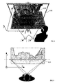
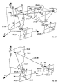
- Figure 1 represents the most basic system for creating a photographic stereogram, where two cameras (1.01) are used to record a three-dimensional object (1.02).
- Fig. 2 this system is represented as a simple projective ray geometry.
- the cameras are set up so that their perspective centers (2.02, 2.03) lie in the same horizontal plane, separated by a horizontal distance (2.04) known as the "base separation.”
- Each point on the object e.g., 2.01 A
- the degree of depth which can be perceived in the resulting stereogram is a function of the distance between the perspective centers of the cameras (2.04) and the distance between each image point and its corresponding object point (e.g., from 2.01 A to 2.05a).
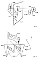
- FIG. 3 One method of viewing stereograms, illustrated in Fig. 3 , involves the use of two projectors (3.01) aligned in such a way that when the two images are projected onto a flat screen (3.03) an observer using stereo glasses (3.02) can perceive various parts of the object as occurring at various depths beyond the plane of the screen.
- Figures 4 and 5 illustrate this point, where 4.01 and 5.01 indicate the location of the screen, and 4.02 and 5.02 indicate the apparent position of the stereo-recorded object as perceived by the viewer. It is also possible to create effects where the object appears to lie in front of the screen or partly in front and partly behind it.
- Figure 6 represents the projection onto a flat screen (6.05) of the stereogram captured in Figure 2 .
- points 6.01 A, B, and C lie in an apparent three-dimensional space beyond the plane of the screen.
- the apparent depth is determined by the horizontal distance between each pair of corresponding image points on the screen (6.02, 6.03, 6.04), called the surface parallax.
- the surface parallax between a pair of stereo image points increases, so too does the apparent depth of the perceived three-dimensional point.
- a reduction in surface parallax results in a reduction of apparent depth.
- the varying degrees of parallax between pairs of corresponding image points is largely governed by the shape of the original object recorded by the stereogram: the farther an object point was from the stereo cameras, the greater the parallax value for the corresponding pairs of image points.
- the coherently stereo-textured model takes an entirely different approach. Rather than trying to achieve a perfect substrate at vast computational expense, it exploits two phenomena briefly discussed above — textural dominance and surface parallax — to create the illusion of a perfect substrate, therefore achieving a very similar effect with vastly less effort.
- the invention accomplishes this through a technique which both simplifies the substrate and registers the stereo imagery to the substrate in such a way as to increase the realistic perception of depth while vastly reducing the computational processing time necessary to create and render the model.
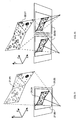
- a ray is then projected through the respective camera's perspective center (10.02, 10.03), and calculations (see Eqns 1.5-1.30) are performed to determine the point at which the rays from corresponding left and right image points would intersect in three-dimensional space (e.g. 10.01 A).
- This hypothetical value is referred to here as the stereo ray intersection point, and in theory it represents the location on the original stereo-recorded object (10.01) which gave rise to the pair of corresponding image points in the stereogram.
- the stereo ray intersection points will be calculated from specially plotted points in the stereo imagery, and these values will determine the placement of the vertices in the three-dimensional substrate, so that each vertex represents a zero parallax point.
- every vertex (zero parallax point) in the entire substrate can be used as a registration point, or a further subset of these vertices may be selected.
- Figure 11 illustrates in a very schematic way a small section of a coherently stereo-textured model, which utilizes three specifically selected zero parallax points (11.01A, B, C). Note that these points have been placed at the locations where pairs of stereo corresponding rays intersect in three-dimensional space, and also that the position of the vertices accurately reflects the position of the original object point on the surface of the stereo-recorded object (11.02). Since this substrate (11.01) is only an approximation of the original object, the surface parallax has only been eliminated for some of the pairs of image points, i.e., those whose rays meet at the surface of the substrate.
- each polygonal facet of the CSTM substrate effectively acts as a mini "screen” onto which sections of the stereogram are mapped or projected.
- Figure 12 illustrates this effect, where each vertex of the polygonal substrate represents the zero parallax point calculated for a specifically selected pair of corresponding rays.
- the stereo imagery (12.02) is registered to the substrate (12.01) at each of these vertices. In between these vertices, where residual surface parallax occurs, varying degrees of depth may be perceived. Due to the principal of textural dominance, discussed earlier, the human visual system ignores the "screen” and sees only the apparent three-dimensional surface ( Fig. 13 ).
- the CSTM therefore implies, rather than explicitly describes, a perfect substrate.
- the coherently stereo-textured model represents a significant paradigm shift in approaches to rendering 3D graphics.
- Explicit modelling and rendering of complex objects in a real-time environment is notoriously difficult and computationally expensive.
- the proposed invention provides a solution to this problem by exploiting the fact that modem graphics hardware is capable of rendering and three-dimensionally mapping two-dimensional imagery much faster and in a much greater volume (in terms of the number of elements processed) than the same number of explicit three dimensional elements or polygons.
- the conventional approach to creating a realistic 3D/VR model of a tree trunk would be to build the most complex and accurate virtual replica of the shape of the tree trunk possible within the constraints of available technology. This could involve millions of polygons to represent each crack and fissure in the bark, and would require vast processing power to achieve real-time interactivity. A photographic image of the tree would then be applied to the surface of the model, a technique known as texture-mapping.
- What a CSTM does instead is to create a much simpler facsimile of the original object using a subsample of the available 3D data — perhaps only a hundred polygons in the case of the tree trunk.
- the stereo imagery is then mapped or rendered onto this model in a way that exploits certain attributes of the human visual system (textural dominance and surface parallax) to create an effect which is extremely realistic to the human eye, but which requires far less computational power to render.
- the invention radically alters the division of labor between the computer and the viewer.
- stereo imagery applied in a specific and coherent way to a greatly simplified version of the original object, a major portion of the processing work involved in visualizing realistic three-dimensional objects and surfaces is transferred from the computer to the human brain.
- the apparent point and its associated convergence angles do not correspond with the distance that the lenses in the eyes would normally adjust to focus to.
- the eyes rotate or swivel to positions as if the apparent surface is real.
- the angles of convergence for the eyes are set to the apparent distance, the lenses in the eyes must focus to the actual distance — the plane of the screen.
- the standard solution for reducing stereoscopic viewing fatigue is to render three-dimensional data sets with very small ranges of parallax, by selecting relatively small values for the base separation between the left and right virtual cameras (or viewing frusta). It is generally desirable to have the average position of the apparent objects close to the plane of the screen so that break-down between view accommodation and convergence is minimized.
- many 3D scenes and data sets can be of a large relative size, naturally incurring a large range of surface parallaxes. For example, there would naturally be a huge range of parallax in a simulation of large building interior if a virtual observer is positioned less than a meter away from a column in the foreground, while gazing out a window sixty meters away.
- the column may be perceived as a distracting double image.
- the rendered viewing parallax can be further reduced by placing the virtual cameras closer together (reducing the horizontal base separation).
- this has the negative effect of greatly compressing the apparent depth of the whole interior scene. When this happens, fine three-dimensional detail is also compressed and the whole simulation appears artificially flat.
- the invention provides a significant solution to the problems associated with the use of interactive stereoscopic display systems by the general public.
- Coherently stereo-textured models are very realistic and convincing, yet they remain within very safe ranges of viewing parallax. This is because the standard technique used to reduce the range of parallax in stereo VR simulations (moving the virtual cameras closer together) does not effect the stereo texture which is inherent in the model.
- a conventional VR model consists of a three-dimensional object with a two-dimensional (monoscopic) image mapped onto it. They are most often viewed monoscopically, and there is no "stereo effect" inherent in the model.
- a conventional VR model only appears in stereo if a pair of virtual cameras are used to feed separate images to the left and right eyes via an appropriate stereo viewing device (stereo glasses, lenticular screen, etc.). In other words, the stereograms of the object are effectively taken as the information is fed out of the computer to the viewer.
- a coherently stereo-textured model differs fundamentally from a standard VR model in that the surface textures of the model are inherently stereoscopic. That is, the stereoscopy is an intrinsic part of the model, not just a function of the way that visual information about the model is output from the computer.
- the CSTM uses a set of specially calculated zero parallax points to determine both the three-dimensional shape of the substrate and the way the stereogram is adhered to it.
- the degree of residual surface parallax in a CSTM is a function of the original camera positions (when the stereogram was taken) and the number and position of the zero parallax points which are used as polygonal vertices and as registration points for the stereo imagery.
- the residual surface parallax is inherent in the model and does not change, regardless of any changes in the base separation of the virtual cameras.
- Figure 14 shows a horizontal slice through the apparent surfaces of various stereo rendered models (looking top down).
- the substrate of a CSTM is composed of far fewer polygons (14.02).
- the perception of depth in the apparent surface (14.03) of the CSTM is a function of the residual surface parallax in the applied stereo imagery.
- the models in 14.01 and 14.02 are illustrated as if rendered with a viewing parallax equivalent to 10 screen pixels.
- the fine three-dimensional features of the conventional model (14.04) are compressed in proportion to the rest of the model and much of the fine detail is lost, because most of the relative depths of the various fine features fall below a certain threshold for human stereo acuity (the smallest increment of depth that can be perceived). In this sense, the majority of the polygons used to represent the complex undulating topography of the conventional model are wasted, as their differences in depth are far too subtle to be perceived.
- the macro features of the CSTM have been compressed (14.05), the micro topography from the apparent residual parallax surface (14.06) has not. Therefore, the fine three-dimensional features are clear and easy to perceive. Even if the base separation of the virtual cameras is set to zero (14.08), the three-dimensional texture of the apparent surface of the CSTM remains largely intact (14.09), while all features in the conventional model have been completely flattened (14.07).
- the CSTM also allows control over micro parallax, using methods entirely separate from those used to control the macro parallax.
- the residual surface parallax in a CSTM is basically controlled by shape of the original object's micro topography and the base separation of the cameras used to record the original object. Therefore the apparent depth of the micro topography can be altered by selecting stereo pairs which employ different horizontal base separations, e.g., if one wishes to amplify the apparent depth of the micro topography in a CSTM, then the residual surface parallax can be increased by using stereograms with a larger base separation.
- the micro parallax of a CSTM is manipulated by controlling the degree of parallax that goes into the model by controlling the base separation of the original cameras (as well as the number and distribution of zero parallax points), while the macro parallax is manipulated by controlling the base separation of the virtual cameras that feed the stereo imagery out to the viewer.
- the CSTM is the only VR modeling technique that allows independent control of macro and micro levels of surface parallax.
- Stereo film and television presentations suffer from the same problems mentioned above, with simultaneously large ranges of viewing parallax when the recorded scenes contain large ranges of spatial depths from foreground to background.
- Stereo filmmakers generally err on the side of visual impact rather than viewer comfort, as it is assumed that the individual viewers will only be watching the stereo presentation for a short time.
- the degree of parallax is too great, eye strain and headaches can occur within a short period of time, and can even begin hours after the viewing event.
- a solution to this problem is even more critical if stereo television is to ever find widespread acceptance, as viewers must be able to watch for prolonged periods without fatigue.
- CSTMs can be used to optimize the ranges of viewing parallax for the stereo presented imagery. This would involve digitizing and generating polygonal substrates for various sets of stereo pairs. Naturally, for a given scene, the stereo cameras will move around in different ways (pan, tilt, zoom, dolly etc.) or present completely different shots of the same scene. Therefore polygonal substrates generated may only suffice for a single pair of stereo frames, or may have extended utility with only minor additions or modifications for an entire film sequence.
- Polygonal substrates can be created for stereo videographed scenes using methods similar to those described (above) for the re-sampling of raw stereo movies.
- the stereo videography can be carried out using multiple cameras at different base separations (a technique that is currently practiced for certain display devices).
- the data sets presented to the stereo television are the various sets of polygonal substrates and their associated streams of stereo imagery (in the form of texture maps with their corresponding sets of zero parallax points).
- the stereo television renders the texture maps to fill the frame and the polygonal substrates.
- the viewer can select different positions from which to view the stereo movie.
- the viewer can decide where in the scene he or she would like to look from - essentially (within limits) "calling the shots" just as a film director might
- the user can zoom in or out, view the action from different angles, or replay a given scene from a different position.
- Well-composed coherently stereo-textured models can tolerate differences in angular view of approximately +/- 75 degrees without noticeable artifacts of stereoscopic shear.
- CSTM technology is particularly useful when virtual sets are used, where actors and presenters are shot against a green or blue screen, and are then later composited (using digital chroma-key techniques) with computer-generated scenery.
- the use of computer-generated scenery would therefore allow a user of streamed CSTMs (derived from the virtual stage sets) to be able to view the scenes from a greater range of positions while the "live" action is still going on.
- the mobility of the user may need to be restricted (depending on the number and positions of the original cameras and the complexity of the scene), to prevent the user from moving into parts of the scene that were occluded from the view positions of the original stereo video cameras, as holes or "data shadows" may occur in these areas.
- the use of virtual sets and scenery would largely eliminate this problem, allowing the user greater access to the virtual scene.
- Streamed CSTMs could be transmitted to consumer stereo television sets (comprising an appropriate decoder and graphics renderer) via various internet or broadcast channels and technologies.
- the streamed CSTMs can also be stored on any of various removable media.
- the use of CSTMs would grant the ability to re-factor specially selected and prepared stereo videographed scenes into more fully realized and complete virtual environments. These specially prepared scenes would allow the viewer to experience a much greater variety of viewing positions and angles that do not reveal various imaging artifacts or data shadows.
- CSTMs For streamed or broadcast CSTMs, various compression schemes can be devised on the basis of human stereo acuity for various corresponding distances. Since the discrimination of various depths decreases with apparent distance, there is little to be gained by modeling CSTMs that significantly exceed the resolutions of depth that can be perceived. Vertices in a CSTM can be set to pre-defined depth values in the form of a look-up table that corresponds to the ranges of human stereo acuity. Special rendering hardware can be constructed to take advantage of the limits and parameters of human stereoscopic perception in order to define an efficient compression scheme for streamed CSTMs.
- This method is primarily applicable to the representation and display of complex real-world objects in a VR environment (i.e., on a stereoscopically-rendered, interactive 3D computer graphics system).
- the basic steps of this process are as follows:
- the "image-derived" method uses data extracted from the original stereograms to determine the shape of the substrate. Since the vertices of the substrate must be placed so that they will function as zero parallax points when the stereo imagery (in the form of texture maps) is applied, it is necessary to determine the location where selected pairs of stereo rays intersect in three-dimensional space. However, even when a stereogram is physically projected into space (e.g., using an optical stereo projection system) it is not normally possible to see or experience where a projected pair of rays intersect. The intersection point must therefore be determined indirectly through the knowledge of certain parameters governing the ray geometry of the stereo imagery.
- CSTMs can be produced even if precise camera data is not available.
- 3D control targets imaged in the frame of the stereogram. If the positions of the targets are known, then even if the orientation of the left and right cameras is unknown and the focal length of the camera is not known precisely, one can still construct a reasonable three-dimensional model and substrate.
- the stereo plotted points are used to calculate intermediate values for corresponding points in 3D space using arbitrary values for all camera and camera position parameters. These intermediate values are calculated using simple parallax equations, and are used to produce a scaled model that corresponds to the plotter coordinate system.
- control targets are also plotted and converted into three dimensions then they represent a referenced set of control targets in the plotter coordinate system. It is therefore possible to calculate a 3D affine transformation, from the control targets referenced to the plotter system to the control targets in the real-world 3D coordinate system. The calculated 3D affine transformation can then be applied to the whole set of 3D plotter coordinate points so that they are transformed into the proper world coordinate system.
- the 3D affine transformation allows for separate scaling in the XYZ directions along with the regular rotation and translation parameters of a conformal transformation.
- each zero parallax point exists at the theoretical location in three-dimensional space where a pair of stereo corresponding rays intersect. Therefore even if the system is spatially ill-defined, a zero parallax point will still eliminate parallax at the surface of the substrate for that pair of stereo corresponding rays. What this means is that various models of varying degrees of spatial fidelity can be further distorted into new shapes and still function as CSTMs, as they still adhere to the principals governing CSTMs.
- CSTMs One of the most important things to get right in the creation of CSTMs is to take stereograms that are highly conducive to human stereopsis, since the main functional component of the system is a human viewer capable of stereopsis. It is therefore highly desirable to have stereograms which are taken such that the left and right imagery are coplanar, and that the principal axes of the left and right lenses are arranged so that they are parallel. Convergent systems are also possible but are more limited in application.
- a digital stereo plotter Using any standard stereo viewing apparatus, the operator employs a "stereo-cursor," which is essentially a target pointer that appears to float in the three-dimensional space of the displayed stereogram.
- the stereo cursor's apparent xy position is generally controlled via a mouse, while the apparent depth of the cursor is controlled via another device, such as a z-wheel or keys on the keyboard that will move the cursor in or out by various increments of depth.
- Figure 15 represents a stereo plotting system, with a stereo-enabled viewing monitor (15.01), eyewear (15.05, 15.06) that feeds separate views to the left and right eyes (15.07, 15.08), an apparent three-dimensional object lying beyond the plane of the monitor screen (15.02), and a stereo cursor (15.09) to plot a point of interest on the apparent three-dimensional object.
- the stereo cursor is composed of a left and right identical marker object (15.03,15.04), and the screen parallax between the displayed left and right marker objects creates the sense of relative depth.
- the system records and displays a marker referenced to the left image's xy coordinate system, and also records and displays a marker on the right image's xy coordinate system.
- the stereo approach to plotting corresponding points can be very sensitive, to allow very sparse or indistinct visual textures to be plotted in three dimensions. For example it would be possible to plot geometries for stereo-imaged clouds and gasses, such as steam or smoke, whether imaged from real life or synthetically rendered on a particle rendering system. This would be very difficult to achieve on a digital mono-comparator.
- Figure 16 represents the general stereo imaging relationship between a fragment of a complex surface (16.01) and the left and right imagery of the associated stereogram (16.02, 16.03), including the effective calibrated focal length of the left and right imaging system (16.06).
- the images in Fig. 16 are represented as positive images, or what are known as diapositives. Normally when rays from three dimensional points project through the perspective center of an imaging system, the image formed in the camera is essentially flipped both horizontally and vertically. It is customary to present the images as diapositives (i.e., right way up) on a stereo viewing screen.
- the projective geometry of the diapositive is the same as that of the negative except for the fact that the diapositive lies in front of the perspective center on the imaging system as depicted in Fig. 16 .
- the perspective centers for the left and right diapositives (16.04, 16.05) lie behind the plane of the imagery. This scheme shall be used for purposes of illustration since, once the basics are understood, it is much easier to represent the projective relationships between all of the various elements that compose the CSTM. This diapositive projective relationship is used in many photogrammetric illustrations and calculations.
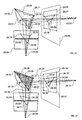
- Figure 17 shows the progression of the stereo plotting processes used to create CSTMs.
- the left and right images are sequentially superimposed using a rendering scheme known as "frame sequential stereo.”
- LCD shutter glasses are used (such as CrystalEyesTM eye wear) that alternately show the left and right images to their respective eyes. This is carried out at a sufficiently fast rate that flicker is not apparent, and the imagery is viewed with apparent depth.
- the sequential superimposition of the stereo imagery allows for global image shifts of one image with respect to the other.
- horizontal screen parallax can be globally controlled to optimize the apparent object in the view frame, so that the object appears relatively close to the plane of the screen.
- the stereograms are shown side by side, although in the actual interface they are normally rendered as a sequential superimposition of the stereo imagery on the view screen or monitor, with only a minor global horizontal shift of the left and right images with respect to each other.
- the left and right digitized stereo images (17.01, 17.02, shown side by side) are presented and sequentially rendered to the left and right eyes; the brain fuses these into a single three-dimensional image of the apparent surface of the original stereo-recorded object (17.03, 17.04).
- Specific points are selected and plotted on the apparent three-dimensional surface using a stereo cursor (17.09, 17.10), which is perceived as a single floating object.
- a stereo cursor 17.09, 17.10
- a pair of corresponding points is simultaneously plotted on the left and right images (17.05, 17.06).
- Other stereo corresponding points are plotted in locations that seem to enable the definition of the basic macro features of the stereoscopically perceived object.
- Marker objects are created to represent the positions where the points were plotted. These plotted markers correspond to stereo plotter coordinates which in turn are referenced to the original image coordinates.
- the connectivity or face sets of the vertices are represented by physically drawing or rendering various triangles superimposed onto the rendered stereograms (17.07, 17.08).
- a single polygon for example is rendered orthographically to the screen, and the values for its vertices are extracted from the positional information corresponding to the left or right plotted points.
- the selection of previously plotted stereo corresponding points to define a triangular polygon is carried out stereoscopically using the stereo cursor. Therefore for each grouping of three pairs of left and right corresponding points, a pair of left and right triangles is created. The left triangle is presented on the left image and the right triangle is presented on the right image.
- 3D triangles are orthographically rendered so that they are in effect flat, in the same plane as the viewing screen and the stereo imagery.
- the left and right sets of triangles are therefore automatically composed into left and right corresponding flat meshes.
- the vertices of the flat meshes contain the same image parallaxes as their corresponding plotted vertices or stereo markers. Therefore, the flat stereoscopic meshes in fact have a three dimensional appearance that precisely stereoscopically overlays the stereoscopically perceived complex object.
- the left and right flat meshes are rendered as wire frame models, so that only their edges are apparent and the stereo imagery is not occluded.
- the next set of processes involves the creation of a three-dimensional polygonal substrate from the left and right flat meshes (18.09,18.10).
- Figure 18 represents the relationship between the plotted stereo points, the vertices of the respective flat meshes, and the original image coordinates referenced to the original left and right image frames (18.01, 18.02).
- using standard photogrammetric techniques it is possible to calculate the three-dimensional position in space for a point that corresponds to the left and right stereo points from a pair of corresponding flat meshes. This is calculated from the X and Y coordinates of the left and right stereo corresponding points (18.03, 18.04) and from a known set of imaging parameters that include the interior and exterior orientation for each left and right camera station (18.07, 18.08).
- the computed three-dimensional X,Y and Z values are then assigned to the corresponding vertex on the third mesh. This is carried out systematically for all the vertices of the left and right stereo "flat" meshes until a new three-dimensionally shaped mesh is created. This therefore means that the three-dimensionally shaped mesh is of exactly the same structure as that of the two stereo flat meshes.
- Figure 19 illustrates the construction of the 3D mesh (19.10) from the left and right stereo flat meshes (19.11, 19.12).
- the enabling schemes for the preferred embodiments of the invention mainly cite the use of the standard 3D computer graphics process known as "texture mapping" as the primary practical method by which the imagery is applied to the substrate for real-time applications.
- texture mapping the standard 3D computer graphics process
- the off-line method of rendering is currently applicable to embodiments of the invention that are used as various physical hardcopy outputs for the CSTM (discussed in greater detail below).
- real-time systems and their associated graphics hardware more readily accept arrays of images (i.e., texture maps with arrays of texture elements, commonly referred to as texels), whose linear number of elements in terms of width and height correspond to powers of 2.
- the maximum dimensions of an individual texture map is typically 1024 by1024 elements (texels).
- the individual left and right stereo images are relatively large, then they need to be decomposed into various subsets of overlapping tiled images that comprise a set of texture maps.
- individual texture maps do not need to be defined, and the correct sampling of the imagery is carried out on the left and right images as a whole. (Future developments in graphics hardware technology may well obviate the need to create prespecified arrays of texture maps of standard pixel dimensions; the use of texture mapping is therefore presented as one possible set of principal enabling steps for particular embodiments of the invention.)
- FIG. 20 shows the left and right stereo images (20.01, 20.02).
- the left and right corresponding texture maps are created by sampling a rectangle (or square) of pixels as a pair of sub-images that are stored as image arrays (20.03, 20.04).
- the standard method of mapping texture imagery onto an associated polygon or set of polygons is by using a special set of two-dimensional mapping coordinates, commonly referred to as 2D "texture coordinates.”
- 2D "texture coordinates” For a given polygon, each vertex is assigned a pair of (U,V) texture mapping coordinates.
- the 3D vertices For a set of three vertices (used to construct an individual polygon in the derived 3D substrate), the 3D vertices have a set of corresponding two-dimensionally plotted points on the left and right imagery. The positions of these plotted image points naturally correspond to the extracted polygonal vertices, by virtue of the initial perspective projection created by the cameras that were used to capture the original stereogram.
- the 3D polygon therefore, is naturally projectively mapped into two-dimensional image space, and will also (if arranged correctly) be projected within the boundaries of a particular texture map.
- texture coordinates are of a parametric form, meaning that the values for the position of an individual texture coordinate are scaled from 0 to a maximum value of 1.
- Figure 20 .05 oshows the position of a left plotted image point.
- the X and Y coordinates of the image point (20.05) correspond to U and V coordinates within the frame of the texture map (20.03).
- a left set of texture coordinates are calculated for the plotted left hand image points.
- a set of right hand texture coordinates are calculated from the positions of the right hand stereo plotted points with respect to the position of the right texture map in the right image.
- the complete minimum set of elements is a three-dimensional substrate, a left texture map with an associated set of left texture coordinates, and a right texture map with an associated set of right texture coordinates.
- the texture coordinates are assigned to the individual vertices of the geometry or substrate.
- most real-time rendering systems and graphics software do not provide an easy interface or access to the geometry database to allow two sets of texture mapping coordinates to be assigned per vertex. There are ways around this problem, and the rendering and assignment of texture coordinates is dealt with in more detail in a later section (Rendering Coherently Stereo-Textured Models).
- a single texture map and a single set of texture coordinates would be used to map the corresponding image back onto the three-dimensional substrate or geometry ( Fig. 21 ).
- the relationship between the texture coordinates and the substrate are such that the imagery is mapped onto the substrate as if it had been projected.
- this conventional scheme when the model is stereoscopically rendered in a VR system it generally has a crude appearance unless a high density of (computationally burdensome) polygons are used to effect a reasonable representation of the complex surface.
- the left and right stereo imagery is texture-mapped onto the substrate as shown in Fig. 22 .0; the substrate is shown as it would appear without being stereo viewed (i.e., with images overlapping rather than fused).
- the vertices of the substrate act as zero parallax points, eliminating surface parallax for pairs of projectively mapped corresponding image points.
- the larger portion of their surface parallaxes are eliminated, but there is still some three-dimensional surface parallax that remains.
- These residual surface parallaxes form a continuous and contiguous set of apparent points, which are capable of representing the fine three-dimensional features of the original complex object.
- the texture maps are applied to the polygonal substrate as a real-time process during the rendering and viewing of the CSTM geometry.
- Even using standard proprietary data and file formats for the CSTM there is no commercially available software that can render a CSTM, since most commercial graphics software assume that three-dimensional models have single sets of texture maps and texture coordinates. Therefore a special VR viewer application has to be created. (See Rendering Coherently Stereo-Textured Models for further detail in this regard.)
- texture mapping coordinates it is possible to enforce the original projective relationship between the extracted zero parallax points and the corresponding image points in the left and right images of the stereogram.
- the true projective relationship is maintained for all image points that are projected onto the surface of the substrate, whether or not they have specific U,V texture mapping coordinates created for them.
- the screen image points that correspond to the image points in the texture imagery are correctly sampled and calculated in real-time.
- the individual mapping coordinates for an individual polygon's vertices are used as an accurate guide, from which all other texture image points can be correctly sampled to fill in the entire area of the polygon, scan line by scan line, as the polygon is rendered.
- Figure 23 illustrates this basic relationship between screen space (23.04), the 3D polygon to be textured (23.02), the position in 2D texture space (23.09) for the projected polygon (23.08), and the sampling of intermediate texels (texture pixels) to fill the whole polygon.
- the three-dimensional vertex (23.10) of the polygon corresponds with the mapping coordinates (23.17) in the texture map (23.09).
- This mapping coordinate also corresponds to the left hand component of the image point that was stereo-plotted on the imagery.
- the 3D vertex, its corresponding texture coordinate (and therefore its plotted image coordinate) and the perspective center (23.07) of the left image (23.06) (and hence the texture map) all lie on the same line in three-dimensional space and are said to be collinear. There is therefore a true projective relationship between the texture coordinates and the 3D vertices of the texture-mapped polygon. Similar correspondences also exist between the other vertices of the 3D polygon and their corresponding 2D texture mapping coordinates, (i.e., 23.11 to 23.16, and 23.12 to 23.18).
- the projected position (23.03) of the 3D polygon into 2D screen space (23.04) is governed by the position of the virtual camera's perspective centre (23.05).
- the same vertices of the polygon in 3D space have corresponding mapping points that effectively project into 2D texture space, defining a second theoretical polygon (23.08).
- Fig. 24 shows the position of a current rendering scan line (24.01) in screen space.
- an individual pixel (24.11) on the scan line is projected into 3D space to determine where it would project onto the 3D polygon (24.12).
- the rendering system calculates the correct corresponding location of the 3D-projected 2D pixel (on the polygon) to its correct corresponding location in 2D texture space (24.13).
- 3D computer graphics very few show the specific equations and algorithms to accomplish the required transformation and sampling of the texel data, as it is often only carried out on specialized hardware. Often what is shown is a direct linear interpolation of the screen space coordinates of the projected polygon directly into texture space (similar in fashion to the standard shading technique known as Gouraud shading). However, this transformation is incorrect for our purposes, as the texture image points would be incorrectly mapped.
- CSTMs could be rendered using the computationally less expensive direct linear transformations (from screen space into texture space), but they would have a visually distorted appearance (perhaps something that could be used for lower-end graphics).
- Fig. 24 the correspondence from the 3D polygon into a 2D triangle on the texture map.
- Many different algorithms could be used to effect the correct texture mapping, but it is possible that the 3D triangle can be considered as a 2D flat triangle (in its own plane) that has 2D vertices corresponding to the 2D texture coordinates in 2D texture space.
- Sampling of specific values from the texture map can be carried out in a variety of ways. Probably the best method, in terms of visual quality, is tri-linear interpolation, a well-known technique in 3D computer graphics. This means that all of the sampled texels (texture pixels) between the specified texture coordinates also adhere to the projective relationship originally created by the left image and camera. In other words, the texture mapping is calculated in such a way for all texels that there exists a virtual perspective photographic center. However, the texture mapping does not use the positional information of the original perspective center for the left image or texture map, it only uses the defined corresponding texture coordinates of the 3D polygon.
- the general mechanism by which the correct texture mapping is implemented shall be referred to as having the texture coordinates and texture rendering calculated in such as manner as to preserve the original projective relationship and geometry between the extracted 3D vertices that form the substrate and the stereo corresponding left and right image points.
- the correct mapping of all the texture imagery is an important feature as it allows the extraction of accurate three dimensional measurements from the apparent surface of the CSTM (discussed in detail below).
- the substrate is composed of 3D data derived from measurements of the object itself, rather than from the stereogram that was used to record the object.
- This three-dimensional data can be gathered from a variety of sources, such as hand measurements, plans, diagrams, laser theodolite mapping, laser rangefinder scanning, etc.
- the derived points which will function as zero parallax points, are used to construct the vertices of polygonal face sets or meshes.
- the relative orientation of the stereograms to the object of interest should be known.
- the orientation of the independently derived 3D data should also be known to a common reference frame for the original object and the camera stations that captured the original stereogram.
- the basic methods for implementation, creation, and rendering are very similar to the methods described above for the image-derived process.
- Certain data sets such as very dense or unwieldy point cloud data from laser scans, can be down-sampled to effect a much more efficient representation as a CSTM.
- Laser point clouds can contain many millions of points, the majority of which could be discarded, as all that is required for the CSTM is a substrate that represents the basic macro features of the object.
- the point cloud could be edited into a set of points that best represent the macro features of the object by stereoscopically superimposing the projected 3D points onto the stereo imagery.
- Laser scans frequently contain many positional errors, so any laser 3D points that do not occur on the apparent surface of the stereo viewed object could be edited or removed.
- One potential problem with the object-derived process is the difficulty in achieving an exact "fit" between the substrate and the stereograms, since the data used to generate the vertices of the substrate are not derived from the stereograms themselves.
- Various adjustment techniques could be implemented to effect a more favorable fit.
- the main advantage of the image-derived method is that the substrates and the stereo plotted image coordinates always make a perfect fit.
- This method refers to the creation of CSTMs from synthetically-generated computer graphic models and renderings (e.g. models made in a 3D modelling and rendering program).
- This technique is essentially very similar to the image-derived process, except that the stereogram of the original object is taken with a virtual camera (or cameras) in a 3D modeling or graphics program. If the stereo rendering of a pair of left and right images is created, then these can be used in exactly the same way as the image-derived process for the creation of a CSTM. However, since the stereograms are used to "record" a synthetic computer graphics model, most of the data that is needed to create the CSTM already exists in the model itself.
- the vertices of the 3D mesh or objects can be projected (using standard projective transformation equations, see Eqns 1.1-1.4) into the effective view frames of the rendered stereograms.
- the transformation matrices for the stereo view-frames are already known to the rendering system.
- the stereograms can then be decomposed into various tiled and overlapping texture maps, as described for the image-derived process.
- the projected 3D vertices give rise to a set of 2D image coordinates on the left and right images of the stereogram, which can be converted into the required texture coordinates referenced to their respective texture map. It is therefore a fairly quick and efficient process to create the full compliment of data sets needed for the CSTM: a polygonal substrate, a left set of texture coordinates and texture maps, and a right set of texture coordinates and texture maps.
- CSTMs For computer games, many particle-based rendering effects can be converted into CSTMs, such as miasmas, water, fire, and explosions. It should also be noted that the stereo plotting interface for the image-derived process makes a very efficient method for creating computer graphic models of real-world objects that would otherwise be very difficult and time-consuming to explicitly model from scratch.
- volumetric imagery such as that created by CAT and MRI medical scans.
- the imagery is created as slices through a solid object, with each slice composed of a two-dimensional array of image values.
- a volumetric representation is produced. Instead of pixels, one has voxels.
- volumetric data can be re-sampled to create a CSTM.
- left and right virtual cameras are used to image the volumetric data from specific relative positions.
- the CSTM can be then be created using the image-derived process.
- the CSTM can be created using techniques similar to the object-derived method.
- Various stacked layers of volumetric data can be set to varying degrees of opacity or transparency.
- each layer of pixels can be represented as an array of slightly spaced 3D dots, which permit the viewing of lower layers from various angles.
- CSTMs created from volumetric data may provide an efficient method for representing complex volumetric data across the internet.
- a stereo-enabled internet browser could be configured to display CSTMs, allowing the transmission of small data sets that represent very complex models when viewed, and which would otherwise be too data intensive to transmit, process, or view.
- the basic data sets that comprise the CSTM may be utilized in a number of different ways.
- the schemes adopted mainly assume what is known as a "frame sequential rendering mode."
- frame sequential stereo the left and right rendered views are presented on screen alternately.
- special eye wear such as LCD shutter glasses (e.g. CrystalEyesTM)
- LCD shutter glasses e.g. CrystalEyesTM
- the basic principal is to map the left texture map to the polygonal substrate when the left view is rendered in the VR system, and then to apply the right texture map to the polygonal substrate when the right view is rendered.
- two sets of texture coordinates are required. Texture coordinates really belong to the geometry and not to the texture map. Many people think of the texture map as being "glued" to the model before it is rendered, but in fact texture mapping is a real-time process and the imagery is only applied to the geometry as it is rendered, using the mapping coordinates stored or assigned to the particular sets of corresponding vertices.
- the left and right substrates are made to occupy exactly the same position in three dimensional space when rendered; however, when the left eye view is rendered the right substrate is turned off (via a switch node capable of fast geometry rejection) so that only the left data sets are visible to the left eye, and when the right eye view is rendered, the left substrate is turned off.
- the left and right data sets are always in computer memory, but it is just a case of alternately changing various settings to enable or disable their rendering.
- mapping coordinates of one image (the right image, for purposes of illustration) or some function of those values are used as spatial coordinate values to define the location in space for the vertices of a new (intermediate) flat substrate.
- the mapping coordinates used to map the right image onto the original substrate are assigned to the corresponding vertices of the intermediate substrate with the purpose of mapping the right image onto the intermediate substrate.
- mapping coordinate values of the left image are used as spatial coordinate values to change or redefine the previously set spatial positions of the vertices of the intermediate flat substrate.
- the intermediate substrate is then rendered using an orthogonal view projection or is resampled at the same scale and resolution of the left image to produce a new right image, which is now warped so that the right image's plotted stereo corresponding points fit the left image's mapping coordinates.
- the resulting data sets are organized so that the left image's texture coordinates are assigned to the vertices of the original three-dimensional substrate.
- the left image is applied to the original substrate using the left set of mapping coordinates, and the newly warped right image is also applied to the original substrate using the left image's mapping coordinates, which were originally assigned to the vertices of the original substrate.
- the four main rendering schemes for CSTMS may thus be characterized by the number and relationship of the component parts, as follows:
- Double-sided texture mapping can usually be enabled using high-level rendering commands. Assuming a CSTM that is comprised of a non-enclosed surface, it is possible to move to the back of the surface (in the VR environment) and effectively perceive the "inside out" surface of the CSTM. In other words, if the front surface was of a face, double-sided texture mapping might allow the viewer to walk around the image and look out through the back of the face.
- the texture imagery is applied as if it was painted on a glass surface of negligible thickness. This means that what was once positive relief now becomes negative relief and vice versa. This can be useful for the interpretation of dense complex features. This technique is analogous to the standard photogrammetric stereoscopic technique of creating a pseudoscopic stereogram where the left image is replaced with the right, and right image is replaced with the left.
- a CSTM Once a CSTM has been created by one of the processes outlined above, it can be subjected to further modifications, such as distorting or transforming the polygonal substrate into different shapes. It is assumed that the CSTM used is one that initially conforms to the natural stereo projective geometry of the original stereogram (i.e., the zero parallax points are positioned at the natural stereo intersection of the corresponding stereo rays). The deformations of the substrate are carried out by changing the individual values of the vertices that compose the polygonal substrate. Because the texture coordinates are assigned to the polygonal substrate it is possible to deform the substrate's mesh and still have the texture imagery correspondingly mapped to the surfaces. In other words, the stereo corresponding left and right points are still made to converge at the zero parallax points even though the substrate is distorted into a new shape.
- the substrate When the substrate is flattened (25.06) by changing the values of its 3D vertices, the residual surface parallax still functions to create an apparent 3D surface, but it has been distorted along with the substrate (25.07).
- the flattened CSTM is distorted into a new shape (25.09), and the apparent surface features from the residual surface parallax have again been distorted accordingly (20.08).
- complex surfaces can be recorded using the image-derived technique and can then be further edited and modified to suit specific needs, where CSTMs can be combined with other 3D and modeling data.
- CSTMs deforming CSTMs eliminates the step of creating a 3D substrate conforming to the natural stereo projective geometry. For example, in the image-derived process one plots stereo pairs of points which are turned into corresponding left and right flat meshes. It is then possible to copy either the left or right plotted mesh to form a new flat substrate for the CSTM. Texture coordinates for the left and right texture maps and imagery are calculated in the normal way (as described for the image-derived process). The texture coordinates are then assigned to the vertices of the copied flat mesh that acts as the polygonal substrate for the CSTM. What results is a flattened polygonal substrate for the CSTM, which still exhibits an apparent 3D surface, due to the residual surface parallax.
- This flattened CSTM can then be taken and further distorted into the required shapes.
- stereo corresponding points are still "forced" to converge at the zero parallax points, without having to create an initial substrate that conforms to the natural stereo projective geometry of the original stereogram.
- Figure 30 illustrates the relationship between a CSTM that complies with the natural stereo projective geometry governed by the original stereogram (26.01), and with an arbitrary substrate (26.03) derived from the left image's flat mesh.
- the texture mapping is carried out using the same texture coordinates as that of the stereo ray compliant substrate (26.01), resulting in the same stereo image points being mapped to the same corresponding vertices (zero parallax points) on the arbitrary substrate (26.03).
- the effective new projective relationship is represented by the "imaginary" rays (26.06) that are "forced” to converge onto the arbitrary substrate.
- the fine and complex features of the apparent 3D surface of the arbitrary substrate are distorted accordingly (26.05). This arbitrary substrate can then be taken and further deformed into various shapes depending on the application.
- the zero parallax points remain in a constant position that accurately reflects the exact three-dimensional position of the corresponding point on the original object This is true regardless of whether the zero parallax points are those specially selected to serve as vertices of the polygonal substrate or whether they are "coincidental" zero parallax points occurring between the vertices, where pairs of stereo rays happen to converge at the surface of the substrate. In areas where residual surface parallax occurs, there may be a very minor degree of shear.
- Figure 27 illustrates the specific geometric relationships between the stereoscopically-sheared surface and the true position of the surface.
- An apparent point is viewed on the CSTM's surface at an apparent location P(a). Because of stereoscopic shear relative to the original positions of the left and right camera positions (27.04, 27.05) of the original stereo imagery, P(a) does not occur at the correct spatial 3D position of its corresponding point on the original object.
- a stereo cursor represented as C(1) and C(r) on the left and right view frames (27.01, 27.02) of the stereo rendered images, it is possible to plot the position for the apparent point.
- a 3D cursor object can be placed at the apparent position of P(a).
- the above-mentioned techniques can be used to extract accurate spatial measurements from the apparent surface of a CSTM, or to three-dimensionally plot and insert new points in the substrate's mesh.
- the surface of the mesh can be re-triangulated to incorporate the new points by redefining the polygonal surface.
- a new set of left and right texture coordinates can be computed to be assigned to the new vertex. This therefore means that a newly inserted point now functions as zero parallax point and it occurs at a location that is highly congruent with respect to its corresponding point on the original object's surface.
- CSTM that is composed of a physically built substrate, and to have the stereo imagery mapped, projected, or printed onto the surface of the substrate.
- Providing there is a method for enabling separate left and right views of the projected stereo imagery e.g., circular or linear polarization, or anaglyphic techniques
- the whole system will function as a CSTM.
- One possible hard copy output of the CSTM would be a paper or cardboard model with the stereo imagery printed onto it in the form an anaglyphic stereogram (i.e., one that uses the glasses with separate filters for the left and right eye).
- anaglyphic stereogram i.e., one that uses the glasses with separate filters for the left and right eye.
- the three-dimensional CSTM would first be realized in digital form.
- the polygonal mesh for the substrate has to be flattened in such a way that all the vertices of a particular polygon are not spatially deformed relative to its own plane. It is therefore necessary to determine how to individually rotate various connected polygons along their joining edges so that they flatten out to a single plane. For certain groupings of polygons it is not possible to flatten out all connected and adjoining polygons, without them overlapping in the 2D plane. In such cases it is necessary to determine various break lines in the mesh so that the whole mesh is decomposed into sub meshes, that can be flattened out without having parts of a single subgroup overlapping each other.
- the left and right stereo imagery onto a single flattened substrate, where the left texture map's luminance values are rendered in green, and the right texture map's luminance values are rendered in red.
- the left and right texture maps are treated as black and white tonal imagery.
- the two rendered images can be composited into a single image using a standard 2D image processing application.
- Various tabs can be added to various sub mesh edges to enable the model's edges to be glued or stuck together.
- an analog CSTM would involve creating a simple three-dimensional substrate capable of presenting separate stereo views to the left and right eyes without specialist eyewear.
- the substrate itself would comprise an autostereoscopic display (e.g. using a lenticular screen), with the stereo imagery projected, rendered, or printed onto it, as appropriate.
- the perspective projection of an object point in 3D space onto a 2D image plane is calculated as follows.
- a three dimensional point in space X a , Y a , Z a is projected onto the two dimensional image plane of a camera or imaging system (see Fig.
- X a , Y a , Z a is an object point in 3D space
- X o , Y o , Z o is the 3D position of the perspective centre of the imaging system ⁇
- ⁇ , ⁇ define the rotation and orientation of the imaging system x a , y a the coordinates of the projected image point referenced to the image plane ⁇ scale, or magnification factor for the projection of a single point
- X a Y a Z a X o Y o Z 0 - ⁇ ⁇ r 11 r 21 r 31 r 12 r 22 r 32 r 13 r 23 r 33 x a y a - f Where r 11 , r 12 , r 13 etc.
- Determination of a point in 3d space formed by the intersection of a pair of stereo rays, formed by the projection of a corresponding pair of left and right stereo image points is carried out as follows.
- a stereo system there are two cameras or imaging systems, defined as: X ol , Y ol , Z ol 3D position of the perspective centre of the left imaging system ⁇ l , ⁇ l , ⁇ l rotation and orientation of the left imaging system.
- Equation 1.5 and 1.6 can be expanded to give equations 1.7 through 1.12:
- R x a 2 - y a 2
- Corrected positions for x a and y a can be used for the various image point related calculations, such as those shown above for improved accuracy.
- Two points PoV(left) and Pov(right) are the perspective centres of the left and right viewing frustums used to render the left and right perspective views of the CSTM (see Fig. 27 ).
- the stereo cursor introduced into the field of view can be used to calculate the 3d position of the apparent point, or a 3d cursor can be used that is spatially positioned at the apparent point.
- rays can be constructed from the apparent point P(a) to PoV(left) and PoV(right).
- a surface plane on the substrate is defined by P1, P2, and P3.
- the next step is to calculate the intersection point of the two rays with the surface plane of the substrate to yield the three dimensional positions of the projected image points, B(left) and B(right). It also possible for the projected points to occur on two different polygons, and procedures can be developed that take into account the projection of stereo corresponding points being on two different planes.
- the general set of equations used are those that pertain to the intersection point of a line with a plane, both in three dimensional space, as shown below.
- the true position for the apparent point P(t) is calculated by the intersection point of a second pair of rays.
- One ray is constructed from the 3d position of the left image's perspective centre O(left) through the left projected image point B(left), the other intersecting ray being constructed from the right image's perspective centre O(right) and the projected right image point B(right).
- Both rays intersecting at P(t), the true position for the apparent point being calculated using the equations below for determining the intersection point of two lines (or rays) in three dimensional space.
- the same principals can be used for procedural stereo-texturing of CSTMs.
- P ⁇ 4 x 4 y 4 z 4
- P ⁇ 5 x 5 y 5 z 5
Landscapes
- Engineering & Computer Science (AREA)
- Multimedia (AREA)
- Signal Processing (AREA)
- Processing Or Creating Images (AREA)
- Stereoscopic And Panoramic Photography (AREA)
- Testing, Inspecting, Measuring Of Stereoscopic Televisions And Televisions (AREA)
Claims (40)
- Verfahren zum Bilden einer stereoskopischen Darstellung eines dreidimensionalen Objekts, das die folgenden Schritte beinhaltet:(a) Bereitstellen eines Stereogramms, das eine erste und eine zweite Ansicht des Objekts umfasst;(b) Auswählen, aus der ersten und der zweiten Ansicht, mehrerer Paare von entsprechenden Bildpunkten, die sich auf dreidimensionale Merkmale beziehen, die eine dreidimensionale Form des Objekts repräsentieren, und Ermitteln von Bildkoordinaten für jeden ausgewählten Punkt mit Bezug auf ein Bildkoordinatensystem seiner jeweiligen Ansicht;(c) Ermitteln eines Orts eines natürlichen Konvergenzpunkts oder eines erzwungenen Konvergenzpunkts in Bezug darauf im dreidimensionalen Raum für jedes gewählte Paar von entsprechenden Bildpunkten mit Bezug auf ihre jeweiligen Bildkoordinaten;(d) Bereitstellen eines Substrats (11.01)(12.01) (14.02)(21.01)(23.02)(25.01)(26.01)(26.03)(27.03) mit einer Oberfläche, die von einem Koordinatensatz im dreidimensionalen Raum definiert wird, wobei der Koordinatensatz Orten der natürlichen Konvergenzpunkte oder erzwungenen Konvergenzpunkte entspricht;(e) Anwenden der ersten und zweiten Ansicht auf das Substrat mit jedem Paar von auf ihre jeweiligen Koordinaten auf der Oberfläche des Substrats angewandten entsprechenden Bildpunkten, so dass Oberflächen-Parallaxe für jedes gewählte Paar von entsprechenden Bildpunkten im Wesentlichen eliminiert wird und Rest-Oberflächen-Parallaxe für wenigstens einige nichtgewählte Paare von entsprechenden Bildpunkten auftritt; und(f) Anzeigen des Resultats der Anwendung, so dass die erste Ansicht nur für ein erstes Auge und die zweite Ansicht für ein zweites Auge eines Betrachters sichtbar ist.
- Verfahren nach Anspruch 1, wobei das Substrat eine dreidimensionale Darstellung von Oberflächenmerkmalen der dreidimensionalen Form des Objekts ist.
- Verfahren nach Anspruch 1 oder Anspruch 2, wobei das Substrat mehrere diskrete Oberflächenelemente umfasst.
- Verfahren nach Anspruch 3, wobei die diskreten Oberflächenelemente Polygone sind.
- Verfahren nach Anspruch 3 oder Anspruch 4, wobei jedes gewählte Paar von entsprechenden Bildpunkten auf einen entsprechenden Scheitelpunkt eines diskreten Oberflächenelements angewandt wird.
- Verfahren nach einem der Ansprüche 2 bis 5, wobei das Substrat mit von dem Stereogramm abgeleiteten Daten erzeugt wird.
- Verfahren nach Anspruch 6, wobei das Substrat erzeugt wird durch:(a) Ermitteln eines Satzes von Punkten im dreidimensionalen Raum, an denen sich Paare von mathematisch projizierten Strahlen, die jeweils von jedem Paar von entsprechenden Bildpunkten durch ihre jeweiligen perspektivischen Mittelpunkte passieren, im dreidimensionalen Raum schneiden; und(b) Verwenden des ermittelten Satzes von Punkten im dreidimensionalen Raum zum Erzeugen der Oberfläche des Substrats, so dass der ermittelte Satz von Punkten auf der Oberfläche dem Koordinatensatz entspricht.
- Verfahren nach einem der Ansprüche 2-5, wobei das Substrat mit direkt von dem Objekt abgeleiteten Daten erzeugt wird.
- Verfahren nach Anspruch 8, wobei der Schritt des Auswählens mehrerer Paare von entsprechenden Bildpunkten Folgendes beinhaltet:(a) Ermitteln der Position und Orientierung des Substrats mit Bezug auf den perspektivischen Mittelpunkt der ersten und der zweiten Ansicht; und(b) Auswählen der mehreren Paare von entsprechenden Bildpunkten durch mathematisches Projizieren von Strahlen von allen durch die Oberfläche des Substrats definierten Koordinaten durch die jeweiligen perspektivischen Mittelpunkte der ersten und der zweiten Ansicht.
- Verfahren nach einem der vorherigen Ansprüche, wobei das Objekt ein virtuelles Objekt (z.B. ein digitaler Gegenstand) ist und das Stereogramm durch Rendern von linken und rechten Ansichten des Objekts erzeugt wird.
- Verfahren nach einem der vorherigen Ansprüche, wobei das Substrat ein im physischen Raum vorliegender fühlbarer Gegenstand ist.
- Verfahren nach Anspruch 11, wobei das Substrat aus einem Material konfiguriert ist, das einem Benutzer eine stereoskopische Darstellung des Objekts präsentiert, ohne Verwendung einer stereoskopischen Brille.
- Verfahren nach Anspruch 12, wobei das Substrat ein Lentikularschirm ist.
- Verfahren nach den Ansprüchen 1-10, wobei das Substrat ein virtuelles Substrat (z.B. ein digitaler Gegenstand) ist.
- Verfahren nach Anspruch 14, das ferner den Schritt des Bereitstellens eines Satzes von Benutzer-Bedienelementen beinhaltet, mittels derer ein Betrachter die Basistrennung zwischen der gerenderten linken und rechten Ansicht justieren kann.
- Verfahren nach einem der vorherigen Ansprüche, wobei das Stereogramm eines von mehreren Stereogrammen einer gegebenen Ansicht des Objekts ist, wobei jedes der mehreren Stereogramme eine andere Basistrennung hat; und ferner Bereitstellen eines Satzes von Bildkoordinaten zum Anwenden jedes der mehreren Stereogramme auf das Substrat.
- Verfahren nach Anspruch 16, das ferner den Schritt des Bereitstellens eines Satzes von Benutzer-Bedienelementen beinhaltet, mittels derer ein Betrachter auswählen kann, welches der verfügbaren Stereogramme auf das Substrat angewendet werden soll.
- Verfahren nach einem der vorherigen Ansprüche, wobei das Stereogramm mit einer ersten Basistrennung versehen ist, die einen Parallaxenbereich übersteigt, der normalerweise vom Menschen als angenehm zu betrachten angesehen wird; und das ferner die folgenden Schritte beinhaltet:digitales Rendern der stereoskopischen Darstellung des Objekts mit einer ersten und einer zweiten virtuellen Kamera mit einer zweiten Basistrennung, die einen Parallaxenbereich erzeugt, der vom Menschen als angenehm zu betrachten angesehen wird; undAufzeichnen und Speichern der digitalen gerenderten stereoskopischen Darstellung des Objekts als ein neues Stereogramm.
- Verfahren nach einem der vorherigen Ansprüche, das ferner das Anzeigen der stereoskopischen Darstellung mit einem System beinhaltet, das die Auswahl von wenigstens einem zusätzlichen Paar von entsprechenden Bildpunkten zulässt.
- Verfahren nach Anspruch 19, das ferner die Verwendung des zusätzlich gewählten Paares von entsprechenden Bildpunkten zum Erzeugen eines neuen Satzes von Koordinaten auf der Oberfläche des Substrats beinhaltet, um die Oberfläche des Substrats weiter zu definieren.
- Verfahren nach Anspruch 19, das ferner die Verwendung von wenigstens einem zusätzlich gewählten Paar von entsprechenden Bildpunkten beinhaltet, um Messwerte von Punkten auf dem Substrat abzuleiten, die Oberflächenmerkmalen des Objekts entsprechen.
- Verfahren nach einem der vorherigen Ansprüche, das ferner das Anzeigen der stereoskopischen Darstellung mit einem System beinhaltet, das eine Manipulation und/oder Annotation der stereoskopischen Darstellung in drei Dimensionen zulässt.
- Verfahren nach einem der vorherigen Ansprüche, das ferner die folgenden Schritte beinhaltet:(a) Bereitstellen eines ersten Satzes von Bildkoordinaten zum Anwenden der ersten Ansicht des Stereogramms auf das Substrat; und(b) Bereitstellen eines zweiten Satzes von Bildkoordinaten zum Anwenden der zweiten Ansicht auf das Substrat.
- Verfahren nach Anspruch 23, wobei die stereoskopische Darstellung so gerendert wird, dass der erste Satz von Koordinaten zum Anwenden der ersten Ansicht auf das Substrat verwendet wird, wenn die erste Ansicht angezeigt wird, und der zweite Satz von Koordinaten zum Anwenden der zweiten Ansicht auf das Substrat verwendet wird, wenn die zweite Ansicht angezeigt wird.
- Verfahren nach Anspruch 23, wobei das Substrat ferner erste und zweite Substratkomponenten umfasst, wobei jede Substratkomponente eine dreidimensionale Form des Objekts darstellt und eine Oberfläche hat, die einen Satz von Koordinaten im dreidimensionalen Raum definiert, und wobei der Schritt des Anwendens der ersten und der zweiten Ansicht des Stereogramms auf das Substrat die Verwendung des ersten Satzes von Bildkoordinaten zum Anwenden der ersten Ansicht auf die erste Substratkomponente und die Verwendung des zweiten Satzes von Bildkoordinaten zum Anwenden der zweiten Ansicht auf die zweite Substratkomponente beinhaltet.
- Verfahren nach einem der Ansprüche 1-22, wobei:(a) die erste Ansicht so verzerrt ist, dass die Position jedes gewählten Bildpunkts mit der seines entsprechenden Bildpunkts in der ersten Ansicht übereinstimmt;(b) ein Satz von Bildkoordinaten zum Anwenden der ersten Ansicht des Stereogramms auf das Substrat bereitgestellt wird; und(c) die stereoskopische Darstellung so gerendert wird, dass sowohl die erste Ansicht als auch die verzerrte zweite Ansicht mit Hilfe der Bildkoordinaten der ersten Ansicht auf das Substrat angewendet werden.
- Verfahren nach einem der Ansprüche 23-26, das ferner Wiederholen nach Bedarf für ein Echtzeit-Rendern mit einer Simulationsschleife beinhaltet.
- Verfahren nach den Ansprüchen 1, 3-5 und 10-27, wobei das bereitgestellte Substrat eine beliebige Form hat.
- Verfahren nach einem der vorherigen Ansprüche, wobei das Substrat einer räumlichen Transformation unterzogen wird, um eine neue Form zu erzeugen.
- Verfahren zum Bilden einer Serie von zeitlich sequenzierten stereoskopischen Darstellungen eines Objekts, das die folgenden Schritte beinhaltet:(a) Bereitstellen mehrerer stereoskopischer Darstellungen, die jeweils mit dem Verfahren nach einem der vorherigen Ansprüche gebildet werden; und(b) Anordnen der mehreren stereoskopischen Darstellungen in einer Sequenz zum Betrachten mit einer vorgegebenen Frame-Rate.
- Verfahren nach Anspruch 30, wobei ein einziges Substrat zum Bilden mehrerer Darstellungen verwendet wird.
- Verfahren nach Anspruch 11, das ferner das physische Drucken des Stereogramms auf das Substrat beinhaltet.
- Stereoskopische Darstellung eines Objekts, produziert mit dem Verfahren nach einem der vorherigen Ansprüche.
- Computerprogramm, das Programmbefehle enthält, um einen Computer zu veranlassen, das Verfahren nach einem der Ansprüche 1 bis 32 auszuführen.
- Computerprogramm nach Anspruch 34, das auf einem Aufzeichnungsmedium ausgestaltet ist.
- Computerprogramm nach Anspruch 34, das auf einem Computerspeicher ausgestaltet ist.
- Computerprogramm nach Anspruch 34, das auf einem Festwertspeicher ausgestaltet ist.
- Computerprogramm nach Anspruch 34, das auf einem elektrischen Trägersignal ausgestaltet ist.
- Vorrichtung zum Bilden einer stereoskopischen Darstellung eines Objekts, die Folgendes umfasst:(a) Mittel zum Erzeugen eines Stereogramms, das eine erste und eine zweite Ansicht des Objekts umfasst;(b) Mittel zum Auswählen, aus der ersten und der zweiten Ansicht, mehrerer Paare von entsprechenden Bildpunkten in Bezug auf dreidimensionale Merkmale, die eine dreidimensionale Form des Objekts repräsentieren, und zum Ermitteln von Bildkoordinaten für jeden gewählten Punkt mit Bezug auf ein Bildkoordinatensystem seiner jeweiligen Ansicht;(c) Mittel zum Ermitteln eines Orts eines natürlichen Konvergenzpunktes oder eines erzwungenen Konvergenzpunktes in Bezug darauf im dreidimensionalen Raum für jedes gewählte Paar von entsprechenden Bildpunkten mit Bezug auf ihre jeweiligen Bildkoordinaten;(d) Mittel zum Erzeugen eines Substrats (11.01) (12.01)(14.02)(21.01)(23.02)(25.01)(26.01)(26.03)(27.03) mit einer Oberfläche, die von einem Koordinatensatz im dreidimensionalen Raum definiert wird, wobei der Koordinatensatz Orten der natürlichen Konvergenzpunkte oder erzwungenen Konvergenzpunkte entspricht; und(e) Mittel zum Anwenden der ersten und der zweiten Ansicht auf das erzeugte Substrat mit jedem Paar von auf ihre jeweiligen Koordinaten auf der Oberfläche des Substrats angewandten entsprechenden Bildpunkten, so dass Oberflächen-Parallaxe im Wesentlichen für jedes gewählte Paar von entsprechenden Bildpunkten eliminiert wird und Rest-Oberflächen-Parallaxe für wenigstens einige nichtgewählte Paare von entsprechenden Bildpunkten auftritt.
- Vorrichtung nach Anspruch 39, wobei das Mittel zum Erzeugen eines Substrats so konfiguriert ist, dass es ein Substrat erzeugt, das eine dreidimensionale Darstellung von Oberflächenmerkmalen der dreidimensionalen Form des Objekts ist.
Applications Claiming Priority (2)
| Application Number | Priority Date | Filing Date | Title |
|---|---|---|---|
| GBGB0322840.0A GB0322840D0 (en) | 2003-09-30 | 2003-09-30 | Stereoscopic imaging |
| PCT/GB2004/004155 WO2005034527A1 (en) | 2003-09-30 | 2004-09-30 | Stereoscopic imaging |
Publications (2)
| Publication Number | Publication Date |
|---|---|
| EP1668919A1 EP1668919A1 (de) | 2006-06-14 |
| EP1668919B1 true EP1668919B1 (de) | 2013-02-20 |
Family
ID=29287101
Family Applications (1)
| Application Number | Title | Priority Date | Filing Date |
|---|---|---|---|
| EP04768698A Expired - Lifetime EP1668919B1 (de) | 2003-09-30 | 2004-09-30 | Stereoskopische bilderstellung |
Country Status (6)
| Country | Link |
|---|---|
| EP (1) | EP1668919B1 (de) |
| JP (1) | JP4996922B2 (de) |
| AU (1) | AU2004306226B2 (de) |
| CA (1) | CA2540538C (de) |
| GB (1) | GB0322840D0 (de) |
| WO (1) | WO2005034527A1 (de) |
Cited By (1)
| Publication number | Priority date | Publication date | Assignee | Title |
|---|---|---|---|---|
| TWI558167B (zh) * | 2014-12-30 | 2016-11-11 | 友達光電股份有限公司 | 立體影像顯示系統與顯示方法 |
Families Citing this family (16)
| Publication number | Priority date | Publication date | Assignee | Title |
|---|---|---|---|---|
| WO2007142649A1 (en) | 2006-06-09 | 2007-12-13 | Thomson Licensing | Method and system for color correction using three-dimensional information |
| US8538144B2 (en) | 2006-11-21 | 2013-09-17 | Thomson Licensing | Methods and systems for color correction of 3D images |
| KR101417024B1 (ko) | 2007-11-22 | 2014-07-08 | 엘지이노텍 주식회사 | 카메라를 이용한 3d 영상 획득 방법 |
| JP2010123007A (ja) * | 2008-11-21 | 2010-06-03 | Casio Computer Co Ltd | 画像処理装置 |
| CA2683206C (en) * | 2009-10-17 | 2018-07-03 | Hermary Opto Electronics Inc. | Enhanced imaging method and apparatus |
| US8624960B2 (en) | 2010-07-30 | 2014-01-07 | Silicon Image, Inc. | Multi-view display system |
| WO2014047504A1 (en) * | 2012-09-21 | 2014-03-27 | Third Dimension Ip Llc | Convergent angular slice true 3d display |
| KR101389865B1 (ko) | 2013-02-28 | 2014-04-29 | 주식회사 펀진 | 이미지 인식 시스템 및 그를 이용한 이미지 인식 방법 |
| CN107705244B (zh) * | 2017-09-11 | 2021-01-15 | 中国国土资源航空物探遥感中心 | 一种适用于大区域多幅遥感影像的接边纠正方法 |
| CN107833266B (zh) * | 2017-11-02 | 2021-01-15 | 青岛擎鹰信息科技有限责任公司 | 一种基于色块匹配和仿射校正的全息图像获取方法 |
| CN111656409B (zh) * | 2018-01-25 | 2024-12-27 | 索尼公司 | 信息处理装置和信息处理方法 |
| KR102250869B1 (ko) * | 2020-09-09 | 2021-05-11 | 한국전자기술연구원 | 다중 광학식 카메라를 이용한 가상현실 플랫폼에서의 다중 객체 위치 추적 시스템 및 방법 |
| CN112215934B (zh) * | 2020-10-23 | 2023-08-29 | 网易(杭州)网络有限公司 | 游戏模型的渲染方法、装置、存储介质及电子装置 |
| US12113951B2 (en) * | 2021-10-08 | 2024-10-08 | Google Llc | High-resolution pseudo-random dots projector module for depth sensing |
| CN114449249B (zh) * | 2022-01-29 | 2024-02-09 | 深圳市火乐科技发展有限公司 | 图像投影方法、装置、存储介质以及投影设备 |
| CN114581586B (zh) * | 2022-03-09 | 2025-04-22 | 北京百度网讯科技有限公司 | 一种模型基底的生成方法、装置、电子设备及存储介质 |
Family Cites Families (8)
| Publication number | Priority date | Publication date | Assignee | Title |
|---|---|---|---|---|
| JPH0522753A (ja) * | 1991-07-12 | 1993-01-29 | Koudo Eizou Gijutsu Kenkyusho:Kk | 立体映像表示装置 |
| US5905499A (en) * | 1995-07-05 | 1999-05-18 | Fakespace, Inc. | Method and system for high performance computer-generated virtual environments |
| US5940167A (en) * | 1997-03-06 | 1999-08-17 | Gans; Richard | Process and apparatus for displaying an animated image |
| US6031564A (en) * | 1997-07-07 | 2000-02-29 | Reveo, Inc. | Method and apparatus for monoscopic to stereoscopic image conversion |
| AUPO894497A0 (en) * | 1997-09-02 | 1997-09-25 | Xenotech Research Pty Ltd | Image processing method and apparatus |
| JP2000013818A (ja) * | 1998-06-23 | 2000-01-14 | Nec Corp | 立体表示装置及び立体表示方法 |
| EP1085769B1 (de) | 1999-09-15 | 2012-02-01 | Sharp Kabushiki Kaisha | Stereoskopisches Bildaufnahmegerät |
| JP4587601B2 (ja) * | 2000-05-30 | 2010-11-24 | パナソニック株式会社 | 地図表示装置、地図表示方法、地図表示装置において用いられるコンピュータプログラム、及びプログラム記録媒体 |
-
2003
- 2003-09-30 GB GBGB0322840.0A patent/GB0322840D0/en not_active Ceased
-
2004
- 2004-09-30 AU AU2004306226A patent/AU2004306226B2/en not_active Ceased
- 2004-09-30 CA CA2540538A patent/CA2540538C/en not_active Expired - Fee Related
- 2004-09-30 EP EP04768698A patent/EP1668919B1/de not_active Expired - Lifetime
- 2004-09-30 WO PCT/GB2004/004155 patent/WO2005034527A1/en not_active Ceased
- 2004-09-30 JP JP2006530568A patent/JP4996922B2/ja not_active Expired - Lifetime
Cited By (1)
| Publication number | Priority date | Publication date | Assignee | Title |
|---|---|---|---|---|
| TWI558167B (zh) * | 2014-12-30 | 2016-11-11 | 友達光電股份有限公司 | 立體影像顯示系統與顯示方法 |
Also Published As
| Publication number | Publication date |
|---|---|
| JP4996922B2 (ja) | 2012-08-08 |
| CA2540538A1 (en) | 2005-04-14 |
| EP1668919A1 (de) | 2006-06-14 |
| GB0322840D0 (en) | 2003-10-29 |
| CA2540538C (en) | 2014-12-02 |
| JP2007507945A (ja) | 2007-03-29 |
| AU2004306226A1 (en) | 2005-04-14 |
| AU2004306226B2 (en) | 2010-05-27 |
| WO2005034527A1 (en) | 2005-04-14 |
Similar Documents
| Publication | Publication Date | Title |
|---|---|---|
| US7643025B2 (en) | Method and apparatus for applying stereoscopic imagery to three-dimensionally defined substrates | |
| US20120182403A1 (en) | Stereoscopic imaging | |
| US6205241B1 (en) | Compression of stereoscopic images | |
| US9843776B2 (en) | Multi-perspective stereoscopy from light fields | |
| Smolic et al. | Three-dimensional video postproduction and processing | |
| US9342914B2 (en) | Method and system for utilizing pre-existing image layers of a two-dimensional image to create a stereoscopic image | |
| US9438878B2 (en) | Method of converting 2D video to 3D video using 3D object models | |
| US9445072B2 (en) | Synthesizing views based on image domain warping | |
| EP1668919B1 (de) | Stereoskopische bilderstellung | |
| US7983477B2 (en) | Method and apparatus for generating a stereoscopic image | |
| US6791598B1 (en) | Methods and apparatus for information capture and steroscopic display of panoramic images | |
| US9165401B1 (en) | Multi-perspective stereoscopy from light fields | |
| EP2323416A2 (de) | Stereoskopische Bearbeitung für Videoproduktion, Postproduktion und Anzeigeanpassung | |
| US20080246757A1 (en) | 3D Image Generation and Display System | |
| JP2000503177A (ja) | 2次元映像(motion picture)を3次元映像に変換する方法及び装置 | |
| JP2006107213A (ja) | 立体画像印刷システム | |
| Oliveira | Image-based modeling and rendering techniques: A survey | |
| CN101189643A (zh) | 3d图像生成和显示系统 | |
| Knorr et al. | An image-based rendering (ibr) approach for realistic stereo view synthesis of tv broadcast based on structure from motion | |
| Gurrieri et al. | Stereoscopic cameras for the real-time acquisition of panoramic 3D images and videos | |
| Knorr et al. | From 2D-to stereo-to multi-view video | |
| KR20080034419A (ko) | 3d 영상 생성 및 디스플레이 시스템 | |
| KR101163020B1 (ko) | 3차원 모델을 스케일링하는 방법 및 스케일링 유닛 | |
| Knorr et al. | Super-resolution stereo-and multi-view synthesis from monocular video sequences | |
| CA2252063C (en) | System and method for generating stereoscopic image data |
Legal Events
| Date | Code | Title | Description |
|---|---|---|---|
| PUAI | Public reference made under article 153(3) epc to a published international application that has entered the european phase |
Free format text: ORIGINAL CODE: 0009012 |
|
| 17P | Request for examination filed |
Effective date: 20060420 |
|
| AK | Designated contracting states |
Kind code of ref document: A1 Designated state(s): AT BE BG CH CY CZ DE DK EE ES FI FR GB GR HU IE IT LI LU MC NL PL PT RO SE SI SK TR |
|
| RAP1 | Party data changed (applicant data changed or rights of an application transferred) |
Owner name: LANGE, ERIC BELK |
|
| RIN1 | Information on inventor provided before grant (corrected) |
Inventor name: LANGE, ERIC BELK |
|
| DAX | Request for extension of the european patent (deleted) | ||
| 17Q | First examination report despatched |
Effective date: 20120131 |
|
| REG | Reference to a national code |
Ref country code: DE Ref legal event code: R079 Ref document number: 602004041069 Country of ref document: DE Free format text: PREVIOUS MAIN CLASS: H04N0013000000 Ipc: H04N0013040000 |
|
| RIC1 | Information provided on ipc code assigned before grant |
Ipc: H04N 13/04 20060101AFI20120625BHEP |
|
| GRAP | Despatch of communication of intention to grant a patent |
Free format text: ORIGINAL CODE: EPIDOSNIGR1 |
|
| GRAS | Grant fee paid |
Free format text: ORIGINAL CODE: EPIDOSNIGR3 |
|
| GRAA | (expected) grant |
Free format text: ORIGINAL CODE: 0009210 |
|
| AK | Designated contracting states |
Kind code of ref document: B1 Designated state(s): AT BE BG CH CY CZ DE DK EE ES FI FR GB GR HU IE IT LI LU MC NL PL PT RO SE SI SK TR |
|
| REG | Reference to a national code |
Ref country code: GB Ref legal event code: FG4D |
|
| REG | Reference to a national code |
Ref country code: CH Ref legal event code: EP |
|
| REG | Reference to a national code |
Ref country code: AT Ref legal event code: REF Ref document number: 597986 Country of ref document: AT Kind code of ref document: T Effective date: 20130315 |
|
| REG | Reference to a national code |
Ref country code: IE Ref legal event code: FG4D |
|
| REG | Reference to a national code |
Ref country code: DE Ref legal event code: R096 Ref document number: 602004041069 Country of ref document: DE Effective date: 20130418 |
|
| REG | Reference to a national code |
Ref country code: CH Ref legal event code: NV Representative=s name: MEYER AND KOLLEGEN, CH |
|
| REG | Reference to a national code |
Ref country code: NL Ref legal event code: T3 |
|
| REG | Reference to a national code |
Ref country code: AT Ref legal event code: MK05 Ref document number: 597986 Country of ref document: AT Kind code of ref document: T Effective date: 20130220 |
|
| PG25 | Lapsed in a contracting state [announced via postgrant information from national office to epo] |
Ref country code: BG Free format text: LAPSE BECAUSE OF FAILURE TO SUBMIT A TRANSLATION OF THE DESCRIPTION OR TO PAY THE FEE WITHIN THE PRESCRIBED TIME-LIMIT Effective date: 20130520 Ref country code: SE Free format text: LAPSE BECAUSE OF FAILURE TO SUBMIT A TRANSLATION OF THE DESCRIPTION OR TO PAY THE FEE WITHIN THE PRESCRIBED TIME-LIMIT Effective date: 20130220 Ref country code: AT Free format text: LAPSE BECAUSE OF FAILURE TO SUBMIT A TRANSLATION OF THE DESCRIPTION OR TO PAY THE FEE WITHIN THE PRESCRIBED TIME-LIMIT Effective date: 20130220 Ref country code: ES Free format text: LAPSE BECAUSE OF FAILURE TO SUBMIT A TRANSLATION OF THE DESCRIPTION OR TO PAY THE FEE WITHIN THE PRESCRIBED TIME-LIMIT Effective date: 20130531 |
|
| PG25 | Lapsed in a contracting state [announced via postgrant information from national office to epo] |
Ref country code: BE Free format text: LAPSE BECAUSE OF FAILURE TO SUBMIT A TRANSLATION OF THE DESCRIPTION OR TO PAY THE FEE WITHIN THE PRESCRIBED TIME-LIMIT Effective date: 20130220 Ref country code: PL Free format text: LAPSE BECAUSE OF FAILURE TO SUBMIT A TRANSLATION OF THE DESCRIPTION OR TO PAY THE FEE WITHIN THE PRESCRIBED TIME-LIMIT Effective date: 20130220 Ref country code: SI Free format text: LAPSE BECAUSE OF FAILURE TO SUBMIT A TRANSLATION OF THE DESCRIPTION OR TO PAY THE FEE WITHIN THE PRESCRIBED TIME-LIMIT Effective date: 20130220 Ref country code: FI Free format text: LAPSE BECAUSE OF FAILURE TO SUBMIT A TRANSLATION OF THE DESCRIPTION OR TO PAY THE FEE WITHIN THE PRESCRIBED TIME-LIMIT Effective date: 20130220 Ref country code: GR Free format text: LAPSE BECAUSE OF FAILURE TO SUBMIT A TRANSLATION OF THE DESCRIPTION OR TO PAY THE FEE WITHIN THE PRESCRIBED TIME-LIMIT Effective date: 20130521 |
|
| PG25 | Lapsed in a contracting state [announced via postgrant information from national office to epo] |
Ref country code: SK Free format text: LAPSE BECAUSE OF FAILURE TO SUBMIT A TRANSLATION OF THE DESCRIPTION OR TO PAY THE FEE WITHIN THE PRESCRIBED TIME-LIMIT Effective date: 20130220 Ref country code: RO Free format text: LAPSE BECAUSE OF FAILURE TO SUBMIT A TRANSLATION OF THE DESCRIPTION OR TO PAY THE FEE WITHIN THE PRESCRIBED TIME-LIMIT Effective date: 20130220 Ref country code: EE Free format text: LAPSE BECAUSE OF FAILURE TO SUBMIT A TRANSLATION OF THE DESCRIPTION OR TO PAY THE FEE WITHIN THE PRESCRIBED TIME-LIMIT Effective date: 20130220 Ref country code: CZ Free format text: LAPSE BECAUSE OF FAILURE TO SUBMIT A TRANSLATION OF THE DESCRIPTION OR TO PAY THE FEE WITHIN THE PRESCRIBED TIME-LIMIT Effective date: 20130220 Ref country code: DK Free format text: LAPSE BECAUSE OF FAILURE TO SUBMIT A TRANSLATION OF THE DESCRIPTION OR TO PAY THE FEE WITHIN THE PRESCRIBED TIME-LIMIT Effective date: 20130220 |
|
| PG25 | Lapsed in a contracting state [announced via postgrant information from national office to epo] |
Ref country code: CY Free format text: LAPSE BECAUSE OF FAILURE TO SUBMIT A TRANSLATION OF THE DESCRIPTION OR TO PAY THE FEE WITHIN THE PRESCRIBED TIME-LIMIT Effective date: 20130220 |
|
| PLBE | No opposition filed within time limit |
Free format text: ORIGINAL CODE: 0009261 |
|
| STAA | Information on the status of an ep patent application or granted ep patent |
Free format text: STATUS: NO OPPOSITION FILED WITHIN TIME LIMIT |
|
| PG25 | Lapsed in a contracting state [announced via postgrant information from national office to epo] |
Ref country code: IT Free format text: LAPSE BECAUSE OF FAILURE TO SUBMIT A TRANSLATION OF THE DESCRIPTION OR TO PAY THE FEE WITHIN THE PRESCRIBED TIME-LIMIT Effective date: 20130220 |
|
| 26N | No opposition filed |
Effective date: 20131121 |
|
| REG | Reference to a national code |
Ref country code: DE Ref legal event code: R097 Ref document number: 602004041069 Country of ref document: DE Effective date: 20131121 |
|
| PG25 | Lapsed in a contracting state [announced via postgrant information from national office to epo] |
Ref country code: MC Free format text: LAPSE BECAUSE OF FAILURE TO SUBMIT A TRANSLATION OF THE DESCRIPTION OR TO PAY THE FEE WITHIN THE PRESCRIBED TIME-LIMIT Effective date: 20130220 |
|
| REG | Reference to a national code |
Ref country code: IE Ref legal event code: MM4A |
|
| PG25 | Lapsed in a contracting state [announced via postgrant information from national office to epo] |
Ref country code: IE Free format text: LAPSE BECAUSE OF NON-PAYMENT OF DUE FEES Effective date: 20130930 |
|
| PG25 | Lapsed in a contracting state [announced via postgrant information from national office to epo] |
Ref country code: TR Free format text: LAPSE BECAUSE OF FAILURE TO SUBMIT A TRANSLATION OF THE DESCRIPTION OR TO PAY THE FEE WITHIN THE PRESCRIBED TIME-LIMIT Effective date: 20130220 |
|
| PG25 | Lapsed in a contracting state [announced via postgrant information from national office to epo] |
Ref country code: HU Free format text: LAPSE BECAUSE OF FAILURE TO SUBMIT A TRANSLATION OF THE DESCRIPTION OR TO PAY THE FEE WITHIN THE PRESCRIBED TIME-LIMIT; INVALID AB INITIO Effective date: 20040930 Ref country code: LU Free format text: LAPSE BECAUSE OF NON-PAYMENT OF DUE FEES Effective date: 20130930 |
|
| PG25 | Lapsed in a contracting state [announced via postgrant information from national office to epo] |
Ref country code: PT Free format text: LAPSE BECAUSE OF FAILURE TO SUBMIT A TRANSLATION OF THE DESCRIPTION OR TO PAY THE FEE WITHIN THE PRESCRIBED TIME-LIMIT Effective date: 20130220 |
|
| REG | Reference to a national code |
Ref country code: FR Ref legal event code: PLFP Year of fee payment: 13 |
|
| REG | Reference to a national code |
Ref country code: FR Ref legal event code: PLFP Year of fee payment: 14 |
|
| REG | Reference to a national code |
Ref country code: DE Ref legal event code: R079 Ref document number: 602004041069 Country of ref document: DE Free format text: PREVIOUS MAIN CLASS: H04N0013040000 Ipc: H04N0013300000 |
|
| REG | Reference to a national code |
Ref country code: FR Ref legal event code: PLFP Year of fee payment: 15 |
|
| PGFP | Annual fee paid to national office [announced via postgrant information from national office to epo] |
Ref country code: PL Payment date: 20180824 Year of fee payment: 15 |
|
| REG | Reference to a national code |
Ref country code: NL Ref legal event code: MM Effective date: 20191001 |
|
| PG25 | Lapsed in a contracting state [announced via postgrant information from national office to epo] |
Ref country code: NL Free format text: LAPSE BECAUSE OF NON-PAYMENT OF DUE FEES Effective date: 20191001 |
|
| PGFP | Annual fee paid to national office [announced via postgrant information from national office to epo] |
Ref country code: FR Payment date: 20200929 Year of fee payment: 17 |
|
| PGFP | Annual fee paid to national office [announced via postgrant information from national office to epo] |
Ref country code: CH Payment date: 20201001 Year of fee payment: 17 |
|
| REG | Reference to a national code |
Ref country code: CH Ref legal event code: PL |
|
| PG25 | Lapsed in a contracting state [announced via postgrant information from national office to epo] |
Ref country code: FR Free format text: LAPSE BECAUSE OF NON-PAYMENT OF DUE FEES Effective date: 20210930 |
|
| PG25 | Lapsed in a contracting state [announced via postgrant information from national office to epo] |
Ref country code: LI Free format text: LAPSE BECAUSE OF NON-PAYMENT OF DUE FEES Effective date: 20210930 Ref country code: CH Free format text: LAPSE BECAUSE OF NON-PAYMENT OF DUE FEES Effective date: 20210930 |
|
| PGFP | Annual fee paid to national office [announced via postgrant information from national office to epo] |
Ref country code: GB Payment date: 20220928 Year of fee payment: 19 |
|
| PGFP | Annual fee paid to national office [announced via postgrant information from national office to epo] |
Ref country code: DE Payment date: 20220930 Year of fee payment: 19 |
|
| REG | Reference to a national code |
Ref country code: DE Ref legal event code: R119 Ref document number: 602004041069 Country of ref document: DE |
|
| GBPC | Gb: european patent ceased through non-payment of renewal fee |
Effective date: 20230930 |
|
| PG25 | Lapsed in a contracting state [announced via postgrant information from national office to epo] |
Ref country code: GB Free format text: LAPSE BECAUSE OF NON-PAYMENT OF DUE FEES Effective date: 20230930 |
|
| PG25 | Lapsed in a contracting state [announced via postgrant information from national office to epo] |
Ref country code: GB Free format text: LAPSE BECAUSE OF NON-PAYMENT OF DUE FEES Effective date: 20230930 Ref country code: DE Free format text: LAPSE BECAUSE OF NON-PAYMENT OF DUE FEES Effective date: 20240403 |