EP1669158B1 - Procédé de fabrication par laser d'un trou débouchant dans un espace intérieur d'une pièce avec nettoyage par traitement chimique de l'espace intérieur - Google Patents
Procédé de fabrication par laser d'un trou débouchant dans un espace intérieur d'une pièce avec nettoyage par traitement chimique de l'espace intérieur Download PDFInfo
- Publication number
- EP1669158B1 EP1669158B1 EP04028958A EP04028958A EP1669158B1 EP 1669158 B1 EP1669158 B1 EP 1669158B1 EP 04028958 A EP04028958 A EP 04028958A EP 04028958 A EP04028958 A EP 04028958A EP 1669158 B1 EP1669158 B1 EP 1669158B1
- Authority
- EP
- European Patent Office
- Prior art keywords
- wall
- solution
- workpiece
- protective member
- accordance
- Prior art date
- Legal status (The legal status is an assumption and is not a legal conclusion. Google has not performed a legal analysis and makes no representation as to the accuracy of the status listed.)
- Expired - Lifetime
Links
Images
Classifications
-
- B—PERFORMING OPERATIONS; TRANSPORTING
- B23—MACHINE TOOLS; METAL-WORKING NOT OTHERWISE PROVIDED FOR
- B23K—SOLDERING OR UNSOLDERING; WELDING; CLADDING OR PLATING BY SOLDERING OR WELDING; CUTTING BY APPLYING HEAT LOCALLY, e.g. FLAME CUTTING; WORKING BY LASER BEAM
- B23K26/00—Working by laser beam, e.g. welding, cutting or boring
- B23K26/36—Removing material
- B23K26/38—Removing material by boring or cutting
- B23K26/382—Removing material by boring or cutting by boring
-
- B—PERFORMING OPERATIONS; TRANSPORTING
- B23—MACHINE TOOLS; METAL-WORKING NOT OTHERWISE PROVIDED FOR
- B23K—SOLDERING OR UNSOLDERING; WELDING; CLADDING OR PLATING BY SOLDERING OR WELDING; CUTTING BY APPLYING HEAT LOCALLY, e.g. FLAME CUTTING; WORKING BY LASER BEAM
- B23K26/00—Working by laser beam, e.g. welding, cutting or boring
- B23K26/16—Removal of by-products, e.g. particles or vapours produced during treatment of a workpiece
-
- B—PERFORMING OPERATIONS; TRANSPORTING
- B23—MACHINE TOOLS; METAL-WORKING NOT OTHERWISE PROVIDED FOR
- B23K—SOLDERING OR UNSOLDERING; WELDING; CLADDING OR PLATING BY SOLDERING OR WELDING; CUTTING BY APPLYING HEAT LOCALLY, e.g. FLAME CUTTING; WORKING BY LASER BEAM
- B23K26/00—Working by laser beam, e.g. welding, cutting or boring
- B23K26/36—Removing material
- B23K26/38—Removing material by boring or cutting
- B23K26/382—Removing material by boring or cutting by boring
- B23K26/389—Removing material by boring or cutting by boring of fluid openings, e.g. nozzles, jets
-
- B—PERFORMING OPERATIONS; TRANSPORTING
- B23—MACHINE TOOLS; METAL-WORKING NOT OTHERWISE PROVIDED FOR
- B23K—SOLDERING OR UNSOLDERING; WELDING; CLADDING OR PLATING BY SOLDERING OR WELDING; CUTTING BY APPLYING HEAT LOCALLY, e.g. FLAME CUTTING; WORKING BY LASER BEAM
- B23K26/00—Working by laser beam, e.g. welding, cutting or boring
- B23K26/36—Removing material
- B23K26/40—Removing material taking account of the properties of the material involved
-
- B—PERFORMING OPERATIONS; TRANSPORTING
- B23—MACHINE TOOLS; METAL-WORKING NOT OTHERWISE PROVIDED FOR
- B23K—SOLDERING OR UNSOLDERING; WELDING; CLADDING OR PLATING BY SOLDERING OR WELDING; CUTTING BY APPLYING HEAT LOCALLY, e.g. FLAME CUTTING; WORKING BY LASER BEAM
- B23K2101/00—Articles made by soldering, welding or cutting
- B23K2101/006—Vehicles
-
- B—PERFORMING OPERATIONS; TRANSPORTING
- B23—MACHINE TOOLS; METAL-WORKING NOT OTHERWISE PROVIDED FOR
- B23K—SOLDERING OR UNSOLDERING; WELDING; CLADDING OR PLATING BY SOLDERING OR WELDING; CUTTING BY APPLYING HEAT LOCALLY, e.g. FLAME CUTTING; WORKING BY LASER BEAM
- B23K2103/00—Materials to be soldered, welded or cut
- B23K2103/50—Inorganic materials other than metals or composite materials
Definitions
- the invention relates to a method for producing a bore opening into a cavity of a workpiece, in particular a fuel injection nozzle, according to the preamble of claim 1 (see, for example, US Pat. No. 6,070,813).
- the irradiation of the protective device leads to a heating thereof.
- the Heating to be so strong that material is removed from the protective device or evaporated.
- the abraded material of the protective member at least partially adheres to the cavity bounding wall and thus leads to undesirable contamination of the inner surface of the workpiece, such as a fuel injector. If the protective organ has e.g. Copper on and is the cavity bounding wall made of iron or steel, it has proved to be almost impossible to remove the copper deposits from the wall, without damaging it.
- a first method is known from US-A-5,222,617.
- a gas turbine blade is cast around a ceramic core.
- the ceramic core is removed from the turbine blade by a wet chemical process.
- US-A-6 070 813 teaches a method of making a bore opening into a cavity of a fuel injector by means of laser radiation in which a tungsten having protective member is introduced into the cavity to absorb the energy of the laser radiation entering the cavity through the bore ,
- WO 2004/087364 A describes a method for producing a bore opening into a cavity of a fuel injection nozzle by means of laser radiation, in which a ball made of a ceramic material is introduced into the cavity in order to absorb the energy of the hole entering the cavity through the bore To absorb laser radiation.
- the invention has for its object to provide a method of the type mentioned above, which allows the production of a bore opening into a cavity of a workpiece without significantly affecting the nature of a cavity bounding the wall of the workpiece.
- a method with the features of claim 1 and in particular the implementation of a wet-chemical treatment of the wall is provided to selectively remove the deposited material from the wall.
- the chemical treatment is carried out with an alkaline solution of an oxidizing agent.
- the invention is based on the surprising finding that it is possible to selectively remove or etch materials which not only absorb energy-rich laser radiation particularly well, but also withstand the laser radiation particularly well, with respect to materials which are conventionally used in fuel injection nozzles, such as iron or steel.
- selective removal or etching means that one material can be removed particularly well, while the other material is essentially not attacked or removed.
- Both molybdenum and tungsten have particularly high melting temperatures. With a melting temperature of 3380 ° C, tungsten even has the highest melting temperature of all pure metals.
- a protective device having these materials is thus particularly well suited for the absorption of high-energy laser radiation, ie it can be particularly high Withstand energy inputs before it starts to melt or evaporate. The life of such a protective device is therefore even further increased.
- both molybdenum and tungsten despite their high melting temperatures, selectively ablate or etch with respect to iron or steel. Both materials can thus be removed without residue from an iron or steel-containing wall of the workpiece by the chemical aftertreatment according to the invention.
- the selective removal of the attached to the cavity wall bounding the protective material member means in other words a removal of the material from the wall without the wall itself attacked or the surface condition of the wall is otherwise adversely affected.
- the invention thus enables not only a complete and residue-free, but also a particularly gentle removal of Schutzorganffleterials of the cavity bounding wall of the workpiece. This is particularly advantageous if the wall was brought into a desired final state before the production of the bore, for example, was polished.
- the chemical and in particular wet-chemical after-treatment of the workpiece provided according to the invention can be compared with, e.g. mechanical treatment, especially easy to perform.
- the workpiece and in particular the cavity bounding wall must be brought into contact only with a suitable chemical substance, and until such time as the protective organ material deposited on the wall has completely reacted with the chemical substance and is dissolved therein.
- a wet-chemical treatment by means of a chemical solution is provided, a plurality of pierced workpieces can be simultaneously immersed in a tank filled with the chemical solution. This allows a quick implementation of the aftertreatment of a large number of workpieces.
- carrying out a chemical aftertreatment thus means an improved economy of the production of bores, in particular in fuel injection nozzles, by means of laser radiation.
- the protective member has a material absorbing the laser radiation.
- the absorption of the laser radiation is a particularly effective way to reduce the energy of the entering through the bore into the cavity laser radiation.
- the protective element preferably has a material with a particularly high melting and / or boiling temperature.
- a protective device is particularly well suited to irradiation with high-energy laser radiation. In other words, only a minimal amount of material is removed from the protective device by the laser radiation impinging on the protective device. Due to the reduced removal of material, the protective device has an increased service life.
- the protective device has the highest possible oxidation potential and, in particular, an oxidation potential greater than -1 V, measured with respect to a standard hydrogen electrode.
- a too negative oxidation potential leads to an oxidation reaction of the material of the protective device under laser irradiation, by which additional heat would be generated and could burn the protective organ. The life of the protective device is thereby further increased and the cost-effectiveness of the method thus further improved.
- the chemical treatment is carried out with a solution of pH> 9. It has been found that such a basic solution etches molybdenum or tungsten particularly well, but iron or steel, however, can not attack. With a Such a solution, the inventively provided selectivity of the aftertreatment is thus achieved particularly well.
- the alkaline solution comprises sodium hydroxide and / or the oxidizing agent comprises hydrogen peroxide, sodium peroxide or sodium peroxodisulfate.
- the chemical treatment can be carried out, for example, with a solution which has, in the ratio of 10 g of sodium hydroxide (NaOH), 30 ml of a 30% hydrogen peroxide solution (H 2 O 2 ) and 70 ml of water.
- the workpiece is completely immersed in the solution, for example during a period of about 5 minutes, or the cavity is flushed out with the solution.
- Both variants mean a particularly simple implementation of the chemical treatment.
- immersion of the workpiece in the solution even several workpieces can be immersed simultaneously in the solution in the manner of a batch process, whereby the chemical treatment of several workpieces further accelerated and the overall cost of the process is further increased
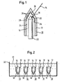
- Fig. 1 shows a workpiece 10 with a wall 12 which is pierced by means of a laser beam 14.
- the workpiece 10 is a fuel injection nozzle formed of an iron or steel material.
- the wall 12 defines a cavity 16 of the workpiece 10, in which the bore 18 produced by the laser beam 14 opens.
- the region of the wall 12 in which the bore 18 opens into the cavity 16 is referred to below as the mouth region 20.
- a protective member 22 is inserted into the cavity 16 during the drilling operation to prevent the laser beam 14 entering the cavity 16 from the bore 18 from striking a wall portion 24 opposite the mouth portion 20 where it will damage the wall 12 or remove material therefrom.
- the protective member 22 is between the mouth region 20 and the opposite wall portion 24 arranged so that the entering into the cavity 16 laser beam 14 can couple into the protective device 22.
- the energy of the injected laser beam 14 is significantly reduced.
- this energy reduction is based on at least partial absorption of the laser beam 14 by the protective device 22. at most a minimal part of the coupled laser radiation leaves the protective member 22 again and this only in the form of low-energy diffuse radiation, which is harmless to the wall 12.
- the energy of the absorbed laser radiation is converted by the protective member 22 into heat.
- the protective element 22 can become so hot that it melts or even evaporates.
- this is formed from a material which has a particularly high melting and / or boiling temperature.
- the material of the protective member 22 has a particularly high oxidation potential, and preferably an oxidation potential of greater than -1 V, measured with respect to a standard hydrogen electrode, so as to prevent an oxidation reaction possible upon heating by the laser beam 14, by which additional heat would be released and the protective device 22 would burn.
- molybdenum and tungsten Materials meeting these requirements are, in accordance with the invention, molybdenum and tungsten.
- the melting temperature of tungsten is 3380 ° C, making it the highest melting temperature of all pure metals.
- the guard 22 In order for the guard 22 to have a maximum amount of material available for the absorption of the laser radiation, the guard 22 is solid, i. not hollow, trained. Due to the massive design of the protective member 22, the stability of the protective member 22 is also increased.
- the protective member 22 may for example have a rod or wire shape.
- the removed by the protective member 22 material at least partially superimposed on the cavity 16 facing inside 28 of the wall 12 at.
- the deposition of the removed or vaporized protective organ material on the wall 12 means an undesirable impairment of the surface quality of the cavity 16 facing inner side 28 of the wall 12. This is even more true if the inside 28 of the wall 12 before the Laserbohrvorgang was brought to a desired final state, for example, polished or otherwise refined.
- a chemical treatment of the wall 12 and in particular the inside 28 of the wall 12 intended is based in the illustrated embodiment on an alkaline solution 30 of an oxidizing agent with which the cavity 16 of the workpiece 10 is rinsed after the drilling operation or in which the entire workpiece 10 is immersed.
- FIG. 2 shows a container 32 filled with such an alkaline solution 30 and a plurality of pierced workpieces 10 simultaneously immersed in the solution 30.
- the solution 30 in the ratio of 10 g of sodium hydroxide (NaOH), 30 ml of a 30% hydrogen peroxide solution (H 2 O 2 ) and 70 ml of water.
- the tungsten or molybdenum deposits 26 of the workpieces 10 exposed to the solution 30 are dissolved in the solution 30 according to the following chemical reaction: M + 3H 2 O 2 + 2NaOH ⁇ Na 2 MO 4 + 4H 2 O, (1) where M is tungsten or molybdenum for the metal.
- the reaction (1) basically takes place in the entire pH range.
- the equilibrium of equation (2) is on the left hand side, i.e., on the left hand side. Oxidation takes place increasingly, provided that all substances are present in unit concentration.
- the tungsten or molybdenum deposits 26 are at least partially passivated at these low pHs. This passivation and the resulting resistance to corrosion cause the tungsten or molybdenum deposits 26 to not be completely removed by a solution 30 having such a low pH.
- the solution 30 has a pH of pH ⁇ 9, the wall 12 of the workpiece 10 formed of iron or steel is also attacked by the solution 30.
- Iron or steel is only passive to the solution 30 when the solution 30 has a pH of pH> 9. If the solution 30 is thus adjusted to pH> 9, then not only is an optimum solubility of the tungsten or molybdenum in the solution 30, but also a passivity of iron or steel relative to the solution 30. This allows selective removal of the deposits 26 from the wall 12, ie the wall 12 remains intact while the deposits 26 are completely removed.
- the workpieces 10 need only be rinsed in water, dried and optionally oiled.
Landscapes
- Engineering & Computer Science (AREA)
- Physics & Mathematics (AREA)
- Optics & Photonics (AREA)
- Plasma & Fusion (AREA)
- Mechanical Engineering (AREA)
- Laser Beam Processing (AREA)
- Coating By Spraying Or Casting (AREA)
- Fuel-Injection Apparatus (AREA)
- ing And Chemical Polishing (AREA)
Claims (8)
- Procédé pour produire un perçage (18) débouchant dans une cavité (16) d'une pièce (10), en particulier d'un injecteur de carburant, dans lequel :on produit le perçage (18) au moyen d'un rayonnement laser (14);on agence un organe de protection (22), contenant du molybdène ou du tungstène, entre une zone d'embouchure (20) d'une paroi (12) délimitant la cavité (16) de la pièce (10), dans laquelle le perçage fini (18) débouche dans la cavité (16), et une section (24) de paroi (12) en regard de la zone d'embouchure (20); etl'énergie du rayonnement laser (14) pénétrant par le perçage (18) dans la cavité (16) est diminuée par l'organe de protection (22), ce par quoi du matériau est enlevé de l'organe de protection (22) et se dépose au moins partiellement sur la paroi (12),caractérisé en ce que
on réalise un traitement chimique de la paroi (12) pour éliminer de manière sélective le matériau déposé (26) de la paroi (12), le traitement chimique étant effectué avec une solution alcaline (30) d'un agent d'oxydation. - Procédé selon la revendication 1, caractérisé en ce que
l'organe de protection (22) contient un matériau absorbant le rayonnement laser (14). - Procédé selon la revendication 1 ou 2, caractérisé en ce que
l'organe de protection (22) contient un matériau ayant une température de fusion et/ou d'ébullition élevée. - Procédé selon l'une quelconque des revendications précédentes, caractérisé en ce que
l'organe de protection (22) présente un potentiel d'oxydation le plus élevé possible et, en particulier, un potentiel d'oxydation supérieur à -1 V, mesuré par rapport à une électrode à hydrogène standard. - Procédé selon l'une quelconque des revendications précédentes, caractérisé en ce que
la solution (30) présente une valeur de pH > 9. - Procédé selon l'une quelconque des revendications précédentes, caractérisé en ce que
la solution alcaline (30) contient de l'hydroxyde de sodium et/ou en ce que l'agent d'oxydation contient du peroxyde d'hydrogène, du peroxyde de sodium ou du peroxodisulfate de sodium. - Procédé selon l'une quelconque des revendications précédentes, caractérisé en ce que
le traitement chimique est effectué à l'aide d'une solution (30) qui contient au prorata 10 g d'hydroxyde de sodium (NaOH), 30 ml d'une solution de peroxyde d'hydrogène à 30% (H2O2) et 70 ml d'eau. - Procédé selon l'une quelconque des revendications précédentes, caractérisé en ce que
on immerge la pièce (10), par exemple pendant une durée d'environ 5 mn, entièrement dans la solution (30) ou en ce que l'on rince la cavité (16) avec la solution (30).
Priority Applications (3)
| Application Number | Priority Date | Filing Date | Title |
|---|---|---|---|
| EP04028958A EP1669158B1 (fr) | 2004-12-07 | 2004-12-07 | Procédé de fabrication par laser d'un trou débouchant dans un espace intérieur d'une pièce avec nettoyage par traitement chimique de l'espace intérieur |
| AT04028958T ATE359146T1 (de) | 2004-12-07 | 2004-12-07 | Verfahren zur herstellung einer in einem hohlraum eines werkstückes mündenden bohrung mittels laserstrahlung mit chemischer behandlung des hohlraumes |
| DE502004003494T DE502004003494D1 (de) | 2004-12-07 | 2004-12-07 | Verfahren zur Herstellung einer in einem Hohlraum eines Werkstückes mündenden Bohrung mittels Laserstrahlung mit chemischer Behandlung des Hohlraumes |
Applications Claiming Priority (1)
| Application Number | Priority Date | Filing Date | Title |
|---|---|---|---|
| EP04028958A EP1669158B1 (fr) | 2004-12-07 | 2004-12-07 | Procédé de fabrication par laser d'un trou débouchant dans un espace intérieur d'une pièce avec nettoyage par traitement chimique de l'espace intérieur |
Publications (2)
| Publication Number | Publication Date |
|---|---|
| EP1669158A1 EP1669158A1 (fr) | 2006-06-14 |
| EP1669158B1 true EP1669158B1 (fr) | 2007-04-11 |
Family
ID=34927676
Family Applications (1)
| Application Number | Title | Priority Date | Filing Date |
|---|---|---|---|
| EP04028958A Expired - Lifetime EP1669158B1 (fr) | 2004-12-07 | 2004-12-07 | Procédé de fabrication par laser d'un trou débouchant dans un espace intérieur d'une pièce avec nettoyage par traitement chimique de l'espace intérieur |
Country Status (3)
| Country | Link |
|---|---|
| EP (1) | EP1669158B1 (fr) |
| AT (1) | ATE359146T1 (fr) |
| DE (1) | DE502004003494D1 (fr) |
Family Cites Families (6)
| Publication number | Priority date | Publication date | Assignee | Title |
|---|---|---|---|---|
| US4559115A (en) * | 1983-05-30 | 1985-12-17 | Inoue-Japax Research Incorporated | Method of and apparatus for machining ceramic materials |
| GB2249279B (en) * | 1990-10-17 | 1994-01-05 | Rolls Royce Plc | Improvements in or relating to drilling turbine blades |
| US5462638A (en) * | 1994-06-15 | 1995-10-31 | International Business Machines Corporation | Selective etching of TiW for C4 fabrication |
| US6303901B1 (en) * | 1997-05-20 | 2001-10-16 | The Regents Of The University Of California | Method to reduce damage to backing plate |
| US6070813A (en) * | 1998-08-11 | 2000-06-06 | Caterpillar Inc. | Laser drilled nozzle in a tip of a fuel injector |
| DE10314844B4 (de) * | 2003-04-01 | 2006-06-08 | Siemens Ag | Verfahren und Verwendung eines Verfahrens zur Herstellung von Durchgangsbohrungen und Düse eines Injektors |
-
2004
- 2004-12-07 AT AT04028958T patent/ATE359146T1/de not_active IP Right Cessation
- 2004-12-07 EP EP04028958A patent/EP1669158B1/fr not_active Expired - Lifetime
- 2004-12-07 DE DE502004003494T patent/DE502004003494D1/de not_active Expired - Lifetime
Also Published As
| Publication number | Publication date |
|---|---|
| EP1669158A1 (fr) | 2006-06-14 |
| ATE359146T1 (de) | 2007-05-15 |
| DE502004003494D1 (de) | 2007-05-24 |
Similar Documents
| Publication | Publication Date | Title |
|---|---|---|
| EP1979125B1 (fr) | Procédé d'usinage de précision de substrats au moyen d'un laser introduit dans un jet de liquide | |
| EP2134887B1 (fr) | Procédé de traitement de précision de substrats, et son utilisation | |
| DE102013223637B4 (de) | Verfahren zum Behandeln eines lasertransparenten Substrats zum anschließenden Trennen des Substrats | |
| DE69300448T2 (de) | Verfahren zum Nitrieren eines Werkstückes aus einer Titanlegierung und Vorrichtung zum Sprühen von Stickstoff und Inertgas. | |
| DE102016213917A1 (de) | Verfahren zur Herstellung eines Bauteils und nach dem Verfahren hergestelltes Bauteil | |
| DE112011101910T5 (de) | Reduzieren von Kupfer- oder Spurenmetallverunreinigungen bei elektrolytischen Plasmaoxidationsbeschichtungen | |
| DE69932540T2 (de) | Verfahren und vorrichtung zur selektiven plattierung eines metallischen trägers mit mittels eines lasers abgetragenen maskierungsschicht | |
| WO2006106061A1 (fr) | Procede pour reparer ou remettre en etat des trous de refroidissement d'un composant enduit d'une turbine a gaz | |
| DE2814044A1 (de) | Verfahren zum herstellen eines loches in einem werkstueck mit hilfe von laserstrahlung | |
| DE2713932C3 (de) | Verfahren zur Herstellung einer korrosionsbeständigen Deckschicht auf rostfreiem Stahl | |
| EP2244848B1 (fr) | Procédé de nettoyage d'un échangeur de chaleur | |
| EP1669158B1 (fr) | Procédé de fabrication par laser d'un trou débouchant dans un espace intérieur d'une pièce avec nettoyage par traitement chimique de l'espace intérieur | |
| EP1270767A1 (fr) | Procédé pour le nettoyage et la passivation de surfaces d'alliages de métaux légers | |
| EP1333976A1 (fr) | Procede de realisation de godets de trame dans une plaque d'heliogravure, et corps de base pouvant etre utilise dans ce procede | |
| DE102005040422A1 (de) | Herstellung von Metall-Nano- und -Mesofasern | |
| DE102010038359B4 (de) | Verfahren zur Herstellung eines Dickschicht-Heizelements für ein wasserführendes Haushaltsgerät und Dickschicht-Heizelement für ein wasserführendes Haushaltsgerät | |
| DE2327878C3 (de) | Verfahren zum Ätzen von mit Elektroden versehenen Halbleiterscheiben für Halbleiterbauelemente | |
| DE102018111874A1 (de) | Verfahren zur Behandlung eines gesägten Halbleiterwafers, Halbleiterwafer und Halbleiterwafer-Solarzelle | |
| DE102022120050A1 (de) | Verfahren und System zum Substratätzen sowie Substrathalter | |
| DE19801013A1 (de) | Verfahren zur Abtragung von Oberflächenschichten mittels deckschichtenverstärkter laserinduzierter Schockwellen | |
| DE102019204979A1 (de) | Verfahren zur Herstellung einer Komponente für EUV-Lithographievorrichtungen | |
| DE102017209229B4 (de) | Verfahren zur Herstellung eines Bauteils und Zwischenprodukt in der Herstellung eines Bauteils | |
| DE2937518A1 (de) | Selektive diffusion von aluminium in einem offenen rohr | |
| DE3029166C2 (de) | Reinigungsverfahren für gelötete Aluminiumbauteile | |
| DE593936C (de) | Verfahren zur Herstellung von ueberzogenen Gluehkathoden |
Legal Events
| Date | Code | Title | Description |
|---|---|---|---|
| PUAI | Public reference made under article 153(3) epc to a published international application that has entered the european phase |
Free format text: ORIGINAL CODE: 0009012 |
|
| 17P | Request for examination filed |
Effective date: 20050824 |
|
| AK | Designated contracting states |
Kind code of ref document: A1 Designated state(s): AT BE BG CH CY CZ DE DK EE ES FI FR GB GR HU IE IS IT LI LT LU MC NL PL PT RO SE SI SK TR |
|
| AX | Request for extension of the european patent |
Extension state: AL BA HR LV MK YU |
|
| GRAP | Despatch of communication of intention to grant a patent |
Free format text: ORIGINAL CODE: EPIDOSNIGR1 |
|
| GRAS | Grant fee paid |
Free format text: ORIGINAL CODE: EPIDOSNIGR3 |
|
| AKX | Designation fees paid |
Designated state(s): AT BE BG CH CY CZ DE DK EE ES FI FR GB GR HU IE IS IT LI LT LU MC NL PL PT RO SE SI SK TR |
|
| GRAA | (expected) grant |
Free format text: ORIGINAL CODE: 0009210 |
|
| AK | Designated contracting states |
Kind code of ref document: B1 Designated state(s): AT BE BG CH CY CZ DE DK EE ES FI FR GB GR HU IE IS IT LI LT LU MC NL PL PT RO SE SI SK TR |
|
| PG25 | Lapsed in a contracting state [announced via postgrant information from national office to epo] |
Ref country code: SI Free format text: LAPSE BECAUSE OF FAILURE TO SUBMIT A TRANSLATION OF THE DESCRIPTION OR TO PAY THE FEE WITHIN THE PRESCRIBED TIME-LIMIT Effective date: 20070411 Ref country code: FI Free format text: LAPSE BECAUSE OF FAILURE TO SUBMIT A TRANSLATION OF THE DESCRIPTION OR TO PAY THE FEE WITHIN THE PRESCRIBED TIME-LIMIT Effective date: 20070411 |
|
| REG | Reference to a national code |
Ref country code: GB Ref legal event code: FG4D Free format text: NOT ENGLISH |
|
| REG | Reference to a national code |
Ref country code: CH Ref legal event code: EP |
|
| REG | Reference to a national code |
Ref country code: IE Ref legal event code: FG4D Free format text: LANGUAGE OF EP DOCUMENT: GERMAN |
|
| REF | Corresponds to: |
Ref document number: 502004003494 Country of ref document: DE Date of ref document: 20070524 Kind code of ref document: P |
|
| PG25 | Lapsed in a contracting state [announced via postgrant information from national office to epo] |
Ref country code: SE Free format text: LAPSE BECAUSE OF FAILURE TO SUBMIT A TRANSLATION OF THE DESCRIPTION OR TO PAY THE FEE WITHIN THE PRESCRIBED TIME-LIMIT Effective date: 20070711 |
|
| PG25 | Lapsed in a contracting state [announced via postgrant information from national office to epo] |
Ref country code: ES Free format text: LAPSE BECAUSE OF FAILURE TO SUBMIT A TRANSLATION OF THE DESCRIPTION OR TO PAY THE FEE WITHIN THE PRESCRIBED TIME-LIMIT Effective date: 20070722 |
|
| PG25 | Lapsed in a contracting state [announced via postgrant information from national office to epo] |
Ref country code: IS Free format text: LAPSE BECAUSE OF FAILURE TO SUBMIT A TRANSLATION OF THE DESCRIPTION OR TO PAY THE FEE WITHIN THE PRESCRIBED TIME-LIMIT Effective date: 20070811 |
|
| ET | Fr: translation filed | ||
| NLV1 | Nl: lapsed or annulled due to failure to fulfill the requirements of art. 29p and 29m of the patents act | ||
| GBV | Gb: ep patent (uk) treated as always having been void in accordance with gb section 77(7)/1977 [no translation filed] |
Effective date: 20070411 |
|
| PG25 | Lapsed in a contracting state [announced via postgrant information from national office to epo] |
Ref country code: PL Free format text: LAPSE BECAUSE OF FAILURE TO SUBMIT A TRANSLATION OF THE DESCRIPTION OR TO PAY THE FEE WITHIN THE PRESCRIBED TIME-LIMIT Effective date: 20070411 |
|
| REG | Reference to a national code |
Ref country code: IE Ref legal event code: FD4D |
|
| PG25 | Lapsed in a contracting state [announced via postgrant information from national office to epo] |
Ref country code: DK Free format text: LAPSE BECAUSE OF FAILURE TO SUBMIT A TRANSLATION OF THE DESCRIPTION OR TO PAY THE FEE WITHIN THE PRESCRIBED TIME-LIMIT Effective date: 20070411 Ref country code: CZ Free format text: LAPSE BECAUSE OF FAILURE TO SUBMIT A TRANSLATION OF THE DESCRIPTION OR TO PAY THE FEE WITHIN THE PRESCRIBED TIME-LIMIT Effective date: 20070411 Ref country code: IE Free format text: LAPSE BECAUSE OF FAILURE TO SUBMIT A TRANSLATION OF THE DESCRIPTION OR TO PAY THE FEE WITHIN THE PRESCRIBED TIME-LIMIT Effective date: 20070411 Ref country code: NL Free format text: LAPSE BECAUSE OF FAILURE TO SUBMIT A TRANSLATION OF THE DESCRIPTION OR TO PAY THE FEE WITHIN THE PRESCRIBED TIME-LIMIT Effective date: 20070411 Ref country code: BG Free format text: LAPSE BECAUSE OF FAILURE TO SUBMIT A TRANSLATION OF THE DESCRIPTION OR TO PAY THE FEE WITHIN THE PRESCRIBED TIME-LIMIT Effective date: 20070711 |
|
| PLBE | No opposition filed within time limit |
Free format text: ORIGINAL CODE: 0009261 |
|
| STAA | Information on the status of an ep patent application or granted ep patent |
Free format text: STATUS: NO OPPOSITION FILED WITHIN TIME LIMIT |
|
| PG25 | Lapsed in a contracting state [announced via postgrant information from national office to epo] |
Ref country code: SK Free format text: LAPSE BECAUSE OF FAILURE TO SUBMIT A TRANSLATION OF THE DESCRIPTION OR TO PAY THE FEE WITHIN THE PRESCRIBED TIME-LIMIT Effective date: 20070411 Ref country code: LT Free format text: LAPSE BECAUSE OF FAILURE TO SUBMIT A TRANSLATION OF THE DESCRIPTION OR TO PAY THE FEE WITHIN THE PRESCRIBED TIME-LIMIT Effective date: 20070411 |
|
| 26N | No opposition filed |
Effective date: 20080114 |
|
| PG25 | Lapsed in a contracting state [announced via postgrant information from national office to epo] |
Ref country code: GB Free format text: LAPSE BECAUSE OF FAILURE TO SUBMIT A TRANSLATION OF THE DESCRIPTION OR TO PAY THE FEE WITHIN THE PRESCRIBED TIME-LIMIT Effective date: 20070411 Ref country code: GR Free format text: LAPSE BECAUSE OF FAILURE TO SUBMIT A TRANSLATION OF THE DESCRIPTION OR TO PAY THE FEE WITHIN THE PRESCRIBED TIME-LIMIT Effective date: 20070712 |
|
| PG25 | Lapsed in a contracting state [announced via postgrant information from national office to epo] |
Ref country code: RO Free format text: LAPSE BECAUSE OF FAILURE TO SUBMIT A TRANSLATION OF THE DESCRIPTION OR TO PAY THE FEE WITHIN THE PRESCRIBED TIME-LIMIT Effective date: 20070411 |
|
| BERE | Be: lapsed |
Owner name: DELPHI TECHNOLOGIES, INC. Effective date: 20071231 |
|
| PG25 | Lapsed in a contracting state [announced via postgrant information from national office to epo] |
Ref country code: MC Free format text: LAPSE BECAUSE OF NON-PAYMENT OF DUE FEES Effective date: 20071231 |
|
| PG25 | Lapsed in a contracting state [announced via postgrant information from national office to epo] |
Ref country code: BE Free format text: LAPSE BECAUSE OF NON-PAYMENT OF DUE FEES Effective date: 20071231 |
|
| PG25 | Lapsed in a contracting state [announced via postgrant information from national office to epo] |
Ref country code: EE Free format text: LAPSE BECAUSE OF FAILURE TO SUBMIT A TRANSLATION OF THE DESCRIPTION OR TO PAY THE FEE WITHIN THE PRESCRIBED TIME-LIMIT Effective date: 20070411 |
|
| PG25 | Lapsed in a contracting state [announced via postgrant information from national office to epo] |
Ref country code: AT Free format text: LAPSE BECAUSE OF NON-PAYMENT OF DUE FEES Effective date: 20071207 |
|
| PG25 | Lapsed in a contracting state [announced via postgrant information from national office to epo] |
Ref country code: CY Free format text: LAPSE BECAUSE OF FAILURE TO SUBMIT A TRANSLATION OF THE DESCRIPTION OR TO PAY THE FEE WITHIN THE PRESCRIBED TIME-LIMIT Effective date: 20070411 |
|
| REG | Reference to a national code |
Ref country code: CH Ref legal event code: PL |
|
| PG25 | Lapsed in a contracting state [announced via postgrant information from national office to epo] |
Ref country code: LU Free format text: LAPSE BECAUSE OF NON-PAYMENT OF DUE FEES Effective date: 20071207 |
|
| PG25 | Lapsed in a contracting state [announced via postgrant information from national office to epo] |
Ref country code: TR Free format text: LAPSE BECAUSE OF FAILURE TO SUBMIT A TRANSLATION OF THE DESCRIPTION OR TO PAY THE FEE WITHIN THE PRESCRIBED TIME-LIMIT Effective date: 20070411 Ref country code: HU Free format text: LAPSE BECAUSE OF FAILURE TO SUBMIT A TRANSLATION OF THE DESCRIPTION OR TO PAY THE FEE WITHIN THE PRESCRIBED TIME-LIMIT Effective date: 20071012 |
|
| PG25 | Lapsed in a contracting state [announced via postgrant information from national office to epo] |
Ref country code: CH Free format text: LAPSE BECAUSE OF NON-PAYMENT OF DUE FEES Effective date: 20081231 Ref country code: LI Free format text: LAPSE BECAUSE OF NON-PAYMENT OF DUE FEES Effective date: 20081231 |
|
| REG | Reference to a national code |
Ref country code: FR Ref legal event code: TP |
|
| PG25 | Lapsed in a contracting state [announced via postgrant information from national office to epo] |
Ref country code: PT Free format text: LAPSE BECAUSE OF FAILURE TO SUBMIT A TRANSLATION OF THE DESCRIPTION OR TO PAY THE FEE WITHIN THE PRESCRIBED TIME-LIMIT Effective date: 20070411 |
|
| REG | Reference to a national code |
Ref country code: FR Ref legal event code: TP Owner name: DELPHI INTERNATIONAL OPERATIONS LUXEMBOURG S.A, LU Effective date: 20140516 |
|
| REG | Reference to a national code |
Ref country code: DE Ref legal event code: R082 Ref document number: 502004003494 Country of ref document: DE Representative=s name: MANITZ, FINSTERWALD & PARTNER GBR, DE |
|
| REG | Reference to a national code |
Ref country code: DE Ref legal event code: R082 Ref document number: 502004003494 Country of ref document: DE Representative=s name: MANITZ, FINSTERWALD & PARTNER GBR, DE Effective date: 20140702 Ref country code: DE Ref legal event code: R081 Ref document number: 502004003494 Country of ref document: DE Owner name: DELPHI INTERNATIONAL OPERATIONS LUXEMBOURG S.A, LU Free format text: FORMER OWNER: DELPHI TECHNOLOGIES HOLDING S.A.R.L., BASCHARAGE, LU Effective date: 20140702 Ref country code: DE Ref legal event code: R082 Ref document number: 502004003494 Country of ref document: DE Representative=s name: MANITZ FINSTERWALD PATENTANWAELTE PARTMBB, DE Effective date: 20140702 |
|
| REG | Reference to a national code |
Ref country code: FR Ref legal event code: PLFP Year of fee payment: 12 |
|
| REG | Reference to a national code |
Ref country code: FR Ref legal event code: PLFP Year of fee payment: 13 |
|
| PG25 | Lapsed in a contracting state [announced via postgrant information from national office to epo] |
Ref country code: IT Free format text: LAPSE BECAUSE OF NON-PAYMENT OF DUE FEES Effective date: 20151207 |
|
| PG25 | Lapsed in a contracting state [announced via postgrant information from national office to epo] |
Ref country code: IT Free format text: LAPSE BECAUSE OF NON-PAYMENT OF DUE FEES Effective date: 20151207 |
|
| PGRI | Patent reinstated in contracting state [announced from national office to epo] |
Ref country code: IT Effective date: 20170710 |
|
| REG | Reference to a national code |
Ref country code: FR Ref legal event code: PLFP Year of fee payment: 14 |
|
| REG | Reference to a national code |
Ref country code: DE Ref legal event code: R082 Ref document number: 502004003494 Country of ref document: DE Ref country code: DE Ref legal event code: R081 Ref document number: 502004003494 Country of ref document: DE Owner name: DELPHI TECHNOLOGIES IP LIMITED, BB Free format text: FORMER OWNER: DELPHI INTERNATIONAL OPERATIONS LUXEMBOURG S.A R.L., BASCHARAGE, LU |
|
| PGFP | Annual fee paid to national office [announced via postgrant information from national office to epo] |
Ref country code: FR Payment date: 20201227 Year of fee payment: 17 |
|
| PGFP | Annual fee paid to national office [announced via postgrant information from national office to epo] |
Ref country code: IT Payment date: 20201221 Year of fee payment: 17 |
|
| PG25 | Lapsed in a contracting state [announced via postgrant information from national office to epo] |
Ref country code: FR Free format text: LAPSE BECAUSE OF NON-PAYMENT OF DUE FEES Effective date: 20211231 |
|
| P01 | Opt-out of the competence of the unified patent court (upc) registered |
Effective date: 20230327 |
|
| PG25 | Lapsed in a contracting state [announced via postgrant information from national office to epo] |
Ref country code: IT Free format text: LAPSE BECAUSE OF NON-PAYMENT OF DUE FEES Effective date: 20211231 |
|
| PGFP | Annual fee paid to national office [announced via postgrant information from national office to epo] |
Ref country code: DE Payment date: 20231108 Year of fee payment: 20 |
|
| REG | Reference to a national code |
Ref country code: DE Ref legal event code: R081 Ref document number: 502004003494 Country of ref document: DE Owner name: PHINIA DELPHI LUXEMBOURG SARL, LU Free format text: FORMER OWNER: DELPHI TECHNOLOGIES IP LIMITED, ST. MICHAEL, BB |
|
| REG | Reference to a national code |
Ref country code: DE Ref legal event code: R071 Ref document number: 502004003494 Country of ref document: DE |