EP1669247A2 - Elektrisches Verbindungsgehäuse - Google Patents
Elektrisches Verbindungsgehäuse Download PDFInfo
- Publication number
- EP1669247A2 EP1669247A2 EP05027216A EP05027216A EP1669247A2 EP 1669247 A2 EP1669247 A2 EP 1669247A2 EP 05027216 A EP05027216 A EP 05027216A EP 05027216 A EP05027216 A EP 05027216A EP 1669247 A2 EP1669247 A2 EP 1669247A2
- Authority
- EP
- European Patent Office
- Prior art keywords
- wiring board
- press
- electric connection
- connection box
- wiring
- Prior art date
- Legal status (The legal status is an assumption and is not a legal conclusion. Google has not performed a legal analysis and makes no representation as to the accuracy of the status listed.)
- Granted
Links
- 238000010276 construction Methods 0.000 claims description 2
- 238000003780 insertion Methods 0.000 description 29
- 230000037431 insertion Effects 0.000 description 29
- 239000004020 conductor Substances 0.000 description 6
- 239000000463 material Substances 0.000 description 4
- 239000011347 resin Substances 0.000 description 4
- 229920005989 resin Polymers 0.000 description 4
- 239000000470 constituent Substances 0.000 description 2
- 230000000694 effects Effects 0.000 description 2
- 238000012986 modification Methods 0.000 description 1
- 230000004048 modification Effects 0.000 description 1
Images



Classifications
-
- B—PERFORMING OPERATIONS; TRANSPORTING
- B60—VEHICLES IN GENERAL
- B60R—VEHICLES, VEHICLE FITTINGS, OR VEHICLE PARTS, NOT OTHERWISE PROVIDED FOR
- B60R16/00—Electric or fluid circuits specially adapted for vehicles and not otherwise provided for; Arrangement of elements of electric or fluid circuits specially adapted for vehicles and not otherwise provided for
- B60R16/02—Electric or fluid circuits specially adapted for vehicles and not otherwise provided for; Arrangement of elements of electric or fluid circuits specially adapted for vehicles and not otherwise provided for electric constitutive elements
- B60R16/023—Electric or fluid circuits specially adapted for vehicles and not otherwise provided for; Arrangement of elements of electric or fluid circuits specially adapted for vehicles and not otherwise provided for electric constitutive elements for transmission of signals between vehicle parts or subsystems
- B60R16/0238—Electrical distribution centers
-
- H—ELECTRICITY
- H01—ELECTRIC ELEMENTS
- H01R—ELECTRICALLY-CONDUCTIVE CONNECTIONS; STRUCTURAL ASSOCIATIONS OF A PLURALITY OF MUTUALLY-INSULATED ELECTRICAL CONNECTING ELEMENTS; COUPLING DEVICES; CURRENT COLLECTORS
- H01R9/00—Structural associations of a plurality of mutually-insulated electrical connecting elements, e.g. terminal strips or terminal blocks; Terminals or binding posts mounted upon a base or in a case; Bases therefor
- H01R9/22—Bases, e.g. strip, block, panel
- H01R9/24—Terminal blocks
- H01R9/2458—Electrical interconnections between terminal blocks
-
- Y—GENERAL TAGGING OF NEW TECHNOLOGICAL DEVELOPMENTS; GENERAL TAGGING OF CROSS-SECTIONAL TECHNOLOGIES SPANNING OVER SEVERAL SECTIONS OF THE IPC; TECHNICAL SUBJECTS COVERED BY FORMER USPC CROSS-REFERENCE ART COLLECTIONS [XRACs] AND DIGESTS
- Y10—TECHNICAL SUBJECTS COVERED BY FORMER USPC
- Y10S—TECHNICAL SUBJECTS COVERED BY FORMER USPC CROSS-REFERENCE ART COLLECTIONS [XRACs] AND DIGESTS
- Y10S439/00—Electrical connectors
- Y10S439/949—Junction box with busbar for plug-socket type interconnection with receptacle
Definitions
- This invention relates to an electric connection box used, for example, in the interior wiring of an automobile.
- the connectors can be mounted on both of the lower and upper cases, but free connection can not be easily made between the lower and upper cases since an insulating plate is disposed between the upper and lower terminals.
- This invention has been made in view of the above circumstances, and an object of the invention is to provide an electric connection box in which the efficiency of layout of wire harnesses is enhanced by inserting connectors from both of upper and lower sides, thereby reducing the cost of the wire harnesses, and also circuits can be freely changed by changing a wiring layout.
- an electric connection box for connecting a plurality of circuits, characterized in that the electric connection box comprises a first cover and a second cover each having connector mounting portions; a first wiring board and a second wiring board which are mounted in a stacked manner between the first and second covers; a plurality of press-contacting terminals which are disposed at one end portions thereof in the connector mounting portions of the first and second covers, and are inserted at the other end portions thereof in the first and second wiring boards; and a connecting wire which is selectively connected to the press-contacting terminals, and is arranged to extend over the first and second wiring boards when the first and second wiring boards are stacked together.
- the first cover is disposed at the upper side
- the second cover is disposed at the lower side, and therefore a plurality of connectors, connected to a plurality of circuits, can be inserted from the upper and lower sides.
- the connecting wire is electrically connected to the press-contacting terminals (inserted in the first wiring board) on the first wiring board, and is also electrically connected to the press-contacting terminals (inserted in the second wiring board) on the second wiring board.
- the connecting wire is arranged to be connected to the first wiring board and the second wiring board, and when the first and second wiring boards are stacked together, the connecting wire, extending over the first and second wiring boards, electrically connects the upper first wiring board-side press-contacting terminals and the lower second wiring board-side press-contacting terminals together.
- the connecting wire are selectively connected to the first wiring board-side press-contacting terminals and the second wiring board-side press-contacting terminals, and therefore can connect the plurality of circuits via the first and second wiring board-side press-contacting terminals on the first and second wiring boards. Therefore, by inserting the connectors from both of the upper and lower sides, the efficiency of layout of wire harnesses is enhanced, and the cost of the wire harnesses can be reduced, and the circuits can be freely changed by changing the wiring layout.
- the electric connection box of the above Paragraph 1) is further characterized in that at least one of the first cover and the second cover has an interconnecting device by which the electric connection box can be connected to another electric connection box identical in construction to the electric connection box.
- the plurality of electric connection boxes can be combined together by the use of the interconnecting device, and therefore many circuits can be connected. And besides, when the wiring operation is to be effected, the plurality of electric connection boxes are separated from each other, and the wiring operation can be effected for each single electric connection box, and therefore it is not necessary to effect the cumbersome operation in the combined condition of the electric connection boxes, so that the efficiency of the wiring operation can be enhanced.
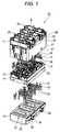
- the first cover 11 is molded of an insulative resin material, and includes a side plate 18 defining four sides thereof, and four connector mounting portions 19 are provided at an upper surface of the first cover.
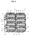
- Each of the connector mounting portions 19 has a plurality of terminal insertion holes 20 (shown in Fig. 5).
- the first cover 11 has slit-like engagement portions 21 which are formed in a lower end of each of opposed side portions of the side plate 18, and extend upwardly from a lower edge thereof.
- a pair of combination-purpose engagement projections 22 (each forming one of two constituent portions of an interconnecting device) are formed on one of the opposed side portions of the side plate 18, while a pair of combination-purpose engagement receptacles 23 (each forming the other constituent portion of the interconnecting device) are formed on the other side portion of the side plate 18.
- the second cover 12 is formed into a generally block-shape, using an insulative resin material as described above for the first cover 11, and has four connector mounting portions 24 provided at its top surface, and a plurality of terminal insertion holes 25 are formed in each of the connector mounting portions 24.
- Engagement projections 26 of a T-shape for being inserted respectively into the corresponding engagement portions 21 of the first cover 11 are formed on and project from each of opposite side surfaces of the second cover 12.
- Retaining projections 27 for retaining engagement with an inner surface of the side plate 18 of the first cover 11 are formed respectively on the other side surfaces of the second cover 12.
- the second cover 12 is fitted into the inside of the side plate 18 of the first cover 11 in which the stacked first and second wiring boards 13 and 14 are received, and the engagement projections 26 are inserted respectively into the engagement portions 21, and the retaining projections 27 are retainingly engaged with the inner surface of the side plate 18, and in this manner the second cover 12 is attached to the first cover 11.
- the first wiring board 13 is formed into a plate-like shape, using an insulative resin material, and has a predetermined thickness.
- a plurality of rows of terminal insertion portions 29 of a hole-like shape (into which press-contacting blades 28, formed respectively at lower ends of the first wiring board-side press-contacting terminals 15, are inserted, respectively) are formed in an upper surface of the first wiring board 13.
- the press-contacting blades 28 of the first wiring board-side press-contacting terminals 15 are press-fitted respectively into the plurality of terminal insertion portions 29 of the first wiring board 13, so that external connection portions 30, formed respectively at upper ends of the first wiring board-side press-contacting terminals 15, project upwardly from the first wiring board 13.
- the second wiring board 14 is formed into a plate-like shape, using an insulative resin material, and has a predetermined thickness.
- a plurality of rows of terminal insertion portions 32 (shown in Fig. 3) of a hole-like shape (into which press-contacting blades 31, formed respectively at upper ends of the second wiring board-side press-contacting terminals 16, are inserted, respectively) are formed in a lower surface of the second wiring board 14.
- the press-contacting blades 31 of the second wiring board-side press-contacting terminals 16 are press-fitted respectively into the plurality of terminal insertion portions 32 of the second wiring board 14, so that external connection portions 33, formed respectively at lower ends of the second wiring board-side press-contacting terminals 16, project downwardly from the second wiring board 14.
- a plurality of jumper wires (not shown) for forming circuits electrically connecting the second wiring board-side press-contacting terminals 16 together are incorporated in those selected from the plurality of terminal insertion portions 32.
- the press-contacting blades 31 of the corresponding press-contacting terminals are electrically connected to the jumper wires, so that the second wiring board-side press-contacting terminals 16 jointly form the circuits.
- the other side portion of the connecting wire, 17 is incorporated in those selected from the plurality of terminal insertion portions 32, and therefore the press-contacting blades 31 of the corresponding press-contacting terminals are electrically connected to the conductor of the connecting wire 17, so that a circuit of the second wiring board-side press-contacting terminals 16 is formed via the connecting wire 17.
- the connecting wire 17 has the conductor (not shown) covered with a sheath 34 (shown in Fig. 2), and has a predetermined length, and is used as a power wire (for example, a +12V wire).
- the one side portion of the connecting wire is incorporated into the selected terminal insertion portions 29 among the plurality of terminal insertion portions 29 at the first wiring board 13, and also the other side portion of the connecting wire 17 is incorporated into the selected terminal insertion portions 32 among the plurality of terminal insertion portions 32 at the second wiring board 14.
- the connecting wire 17 (which is electrically connected to the first wiring board-side terminals 15 inserted respectively in the selected terminal insertion portions 29 of the first wiring board 13, and is also electrically connected to the second wiring board-side terminals 16 inserted respectively in the selected terminal insertion portions 32 of the second wiring board 14) can electrically connect the first and second wiring board-side press-contacting terminals 15 and 16 together with the shortest distance at the upper and lower sides of the two wiring boards 13 and 14. Therefore, there is no fear that this connecting wire is affected by components such as disturbances.
- the connecting wire 17 is incorporated into the selected terminal insertion portions 29 of the first wiring board 13 in a manner to assume a generally I-shape, and then the connecting wire 17 is incorporated into the selected terminal insertion portions 32 of the second wiring board 14 in a manner to assume a generally crank-shape.
- the first and second wiring board-side press-contacting terminals 15 and 16 are press-fitted respectively into the selected terminal insertion portions 29 and 32, so that the conductor of the connecting wire 17 is electrically connected to the first and second wiring board-side press-contacting terminals 15 and 16.
- the connecting wire 17 is mounted on and connected to the first and second wiring boards 13 and 14 disposed in the developed condition.
- the first and second wiring boards 13 and 14 (which are stacked together after the connecting wire 17 is incorporated in them) is received within the first cover 11, and the second cover 12 is attached to the first cover 11, thus assembling the electric connection box 10.
- the combination-purpose engagement projections 22 of the electric connection box 10 are engaged respectively with the combination-purpose engagement receptacles 23 of another electric connection box 10 in an assembled condition, so that the two electric connection boxes 10 are connected or combined together in a unitary manner.
- the number of the electric connection boxes 10 to be interconnected is not limited to two, and can be three or more.
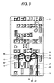
- the connecting wire 17 is incorporated in predetermined terminal insertion portions 29 of the first wiring board 13 in a manner to assume a generally W-shape, and is also incorporated in predetermined terminal insertion portions 32 of the second wiring board 14 disposed on the lower side of the first wiring board 13.
- part of the connecting wire 17 can be withdrawn from the predetermined terminal insertion portion 29, and this withdrawn portion can be incorporated into a newly-selected terminal insertion portion 35 as shown in Fig. 7.
- This operation can be carried out similarly over the second wiring board 14, and therefore can be effected easily before the first and second wiring board-side press-contacting terminals 15 and 16 are press-fitted into the respective terminal insertion portions, and therefore the efficiency of the operation can be enhanced without the need for using a new connecting wire.
- the first cover 11 is disposed at the upper side
- the second cover 12 is disposed at the lower side, and therefore the plurality of connectors, connected to the plurality of circuits, can be inserted from the upper and lower sides.
- the connecting wire 17 is electrically connected to the first wiring board-side press-contacting terminals 15 (inserted in the first wiring board 13) on the first wiring board 13, and is also electrically connected to the second wiring board-side press-contacting terminals 16 (inserted in the second wiring board 14) on the second wiring board 14.
- the plurality of electric connection boxes 10 can be combined together by the use of the interconnecting device (comprising the combination-purpose engagement projections 22 and the combination-purpose receptacles 23), and therefore many circuits can be connected. And besides, when the wiring operation is to be effected, the plurality of electric connection boxes are separated from each other, and the wiring operation can be effected for each single electric connection box, and therefore it is not necessary to effect the cumbersome operation in the combined condition of the electric connection boxes, so that the efficiency of the wiring operation can be enhanced.
- the present invention is not limited to the above embodiment, and suitable modifications, improvements and so on can be made.
- the number of the first wiring board-side press-contacting terminals, as well as the number of the second wiring board-side press-contacting terminals, is determined according to the number of circuits used in a vehicle.
- the electric connection boxes, having the same number of first wiring board-side press-contacting terminals and the same number of second wiring board-side press-contacting terminals can be produced in a large number, in which case those terminals which are not used depending on the kind of vehicle can be used as dummy terminals.
- the connecting wire is not limited to the illustrated sheathed wire, but can be a bare conductor, an electrically-conductive wire or the like.
- the interconnecting device do not always need to be provided on the illustrated first cover 11, but can be provided on the second cover 12, and this is suitably determined according to the easiness of moldability.
Landscapes
- Engineering & Computer Science (AREA)
- Mechanical Engineering (AREA)
- Connection Or Junction Boxes (AREA)
- Multi-Conductor Connections (AREA)
- Connections By Means Of Piercing Elements, Nuts, Or Screws (AREA)
- Coupling Device And Connection With Printed Circuit (AREA)
Applications Claiming Priority (1)
| Application Number | Priority Date | Filing Date | Title |
|---|---|---|---|
| JP2004360158A JP2006174538A (ja) | 2004-12-13 | 2004-12-13 | 電気接続箱 |
Publications (3)
| Publication Number | Publication Date |
|---|---|
| EP1669247A2 true EP1669247A2 (de) | 2006-06-14 |
| EP1669247A3 EP1669247A3 (de) | 2007-08-22 |
| EP1669247B1 EP1669247B1 (de) | 2017-02-08 |
Family
ID=35841745
Family Applications (1)
| Application Number | Title | Priority Date | Filing Date |
|---|---|---|---|
| EP05027216.0A Expired - Lifetime EP1669247B1 (de) | 2004-12-13 | 2005-12-13 | Elektrisches Verbindungsgehäuse |
Country Status (4)
| Country | Link |
|---|---|
| US (1) | US7249956B2 (de) |
| EP (1) | EP1669247B1 (de) |
| JP (1) | JP2006174538A (de) |
| CN (1) | CN100514782C (de) |
Families Citing this family (14)
| Publication number | Priority date | Publication date | Assignee | Title |
|---|---|---|---|---|
| JP3867729B1 (ja) * | 2005-07-21 | 2007-01-10 | 住友電装株式会社 | 電気接続箱 |
| JP4487974B2 (ja) * | 2006-06-05 | 2010-06-23 | 株式会社デンソー | モータドライバ |
| US8654528B2 (en) * | 2006-11-16 | 2014-02-18 | Autonetworks Technologies, Ltd. | Electric connection box |
| JP4885693B2 (ja) * | 2006-12-05 | 2012-02-29 | 株式会社オートネットワーク技術研究所 | 電気接続箱 |
| US7983024B2 (en) * | 2007-04-24 | 2011-07-19 | Littelfuse, Inc. | Fuse card system for automotive circuit protection |
| JP5007249B2 (ja) * | 2008-02-13 | 2012-08-22 | 矢崎総業株式会社 | 電気接続箱の防水構造 |
| US7727022B2 (en) * | 2008-02-14 | 2010-06-01 | Delphi Technologies, Inc. | On harness PCB electrical center |
| WO2012057428A1 (ko) * | 2010-10-25 | 2012-05-03 | 한국단자공업 주식회사 | 인쇄회로기판 및 이를 사용한 차량용 기판블록 |
| JP5625971B2 (ja) * | 2011-02-08 | 2014-11-19 | 住友電装株式会社 | 電気接続箱用の内部回路構成体およびそれを用いた電気接続箱 |
| JP2016015821A (ja) * | 2014-07-02 | 2016-01-28 | 株式会社オートネットワーク技術研究所 | 電気接続箱 |
| US11091275B2 (en) | 2015-10-22 | 2021-08-17 | Droneovation, Inc. | Aerial drone operations support base |
| JP7115271B2 (ja) * | 2018-12-07 | 2022-08-09 | 住友電装株式会社 | 電気接続箱 |
| US11936128B2 (en) | 2021-02-09 | 2024-03-19 | Lear Corporation | Electrical unit with offset terminals |
| US12597749B2 (en) * | 2023-06-20 | 2026-04-07 | Fca Us Llc | Replaceable low voltage connector adapter with integrated fuse design |
Citations (4)
| Publication number | Priority date | Publication date | Assignee | Title |
|---|---|---|---|---|
| JP2000139076A (ja) | 1998-10-30 | 2000-05-16 | Yaskawa Electric Corp | Pwmサイクロコンバータの保護装置およびその保護方法 |
| JP2000139016A (ja) | 1998-08-24 | 2000-05-16 | Yazaki Corp | 配線板の接続構造及び配線板組立体の製造方法 |
| JP2000188814A (ja) | 1998-12-22 | 2000-07-04 | Sumitomo Wiring Syst Ltd | 電気接続箱 |
| JP2001320814A (ja) | 2000-05-09 | 2001-11-16 | Yazaki Corp | 電気接続箱 |
Family Cites Families (17)
| Publication number | Priority date | Publication date | Assignee | Title |
|---|---|---|---|---|
| US5501605A (en) * | 1993-06-07 | 1996-03-26 | Yazaki Corporation | Wiring harness assembly for vehicles |
| US5805402A (en) * | 1993-06-09 | 1998-09-08 | Ut Automotive Dearborn, Inc. | Integrated interior trim and electrical assembly for an automotive vehicle |
| US6137054A (en) * | 1994-01-25 | 2000-10-24 | Yazaki Corporation | Wire-circuit sheet and electric junction box thereof |
| US5653607A (en) * | 1994-07-27 | 1997-08-05 | Sumitomo Wiring Systems, Ltd. | Electric connection casing |
| JP2962160B2 (ja) * | 1994-09-14 | 1999-10-12 | 住友電装株式会社 | 電気接続箱 |
| JPH08171962A (ja) * | 1994-12-15 | 1996-07-02 | Sumitomo Wiring Syst Ltd | ジャンクションボックス |
| JP2924681B2 (ja) * | 1994-12-28 | 1999-07-26 | 住友電装株式会社 | 電気接続箱 |
| EP1014501A1 (de) * | 1998-12-22 | 2000-06-28 | Sumitomo Wiring Systems, Ltd. | Elektrischer Verteilerkasten, dessen Herstellungsmethode, Verdrahtungssammelschiene für einen elektrischen Verteilerkasten und die Herstellungsmethode |
| JP3399383B2 (ja) * | 1998-12-22 | 2003-04-21 | 住友電装株式会社 | 電気接続箱 |
| EP1187258A1 (de) * | 2000-08-30 | 2002-03-13 | Kojin, Ltd. | Sicherungs- und Relaiskasten für Kraftfahrzeuge |
| JP2002186140A (ja) * | 2000-12-15 | 2002-06-28 | Yazaki Corp | 電気接続箱の回路構造及びその回路形成方法 |
| JP2002330522A (ja) * | 2001-04-27 | 2002-11-15 | Yazaki Corp | 電気接続箱 |
| JP2003009347A (ja) * | 2001-06-20 | 2003-01-10 | Sumitomo Wiring Syst Ltd | 電気接続箱 |
| JP3954915B2 (ja) * | 2002-05-29 | 2007-08-08 | 矢崎総業株式会社 | 電気接続箱とその製造方法 |
| JP2004072934A (ja) * | 2002-08-08 | 2004-03-04 | Yazaki Corp | 電気接続箱 |
| US6926541B2 (en) * | 2002-08-30 | 2005-08-09 | Yazaki Corporation | Mounting structure of electric junction box |
| JP4289207B2 (ja) * | 2004-04-27 | 2009-07-01 | 株式会社デンソー | 電子制御装置 |
-
2004
- 2004-12-13 JP JP2004360158A patent/JP2006174538A/ja active Pending
-
2005
- 2005-12-13 EP EP05027216.0A patent/EP1669247B1/de not_active Expired - Lifetime
- 2005-12-13 CN CNB2005101369955A patent/CN100514782C/zh not_active Expired - Lifetime
- 2005-12-13 US US11/299,777 patent/US7249956B2/en not_active Expired - Lifetime
Patent Citations (4)
| Publication number | Priority date | Publication date | Assignee | Title |
|---|---|---|---|---|
| JP2000139016A (ja) | 1998-08-24 | 2000-05-16 | Yazaki Corp | 配線板の接続構造及び配線板組立体の製造方法 |
| JP2000139076A (ja) | 1998-10-30 | 2000-05-16 | Yaskawa Electric Corp | Pwmサイクロコンバータの保護装置およびその保護方法 |
| JP2000188814A (ja) | 1998-12-22 | 2000-07-04 | Sumitomo Wiring Syst Ltd | 電気接続箱 |
| JP2001320814A (ja) | 2000-05-09 | 2001-11-16 | Yazaki Corp | 電気接続箱 |
Also Published As
| Publication number | Publication date |
|---|---|
| EP1669247B1 (de) | 2017-02-08 |
| EP1669247A3 (de) | 2007-08-22 |
| JP2006174538A (ja) | 2006-06-29 |
| US20060128181A1 (en) | 2006-06-15 |
| CN1790849A (zh) | 2006-06-21 |
| US7249956B2 (en) | 2007-07-31 |
| CN100514782C (zh) | 2009-07-15 |
Similar Documents
| Publication | Publication Date | Title |
|---|---|---|
| US5057026A (en) | Electric junction box | |
| JP4172334B2 (ja) | 電気接続箱 | |
| EP1674346B1 (de) | Elektrisches Verbindungsgehäuse und Verfahren zu dessen Zusammenbau | |
| US5478244A (en) | Hybrid junction box | |
| JP2752010B2 (ja) | 電気接続箱 | |
| US7927111B2 (en) | Electrical junction box | |
| EP0701924B1 (de) | Elektrischer Verbindungskasten | |
| US7249956B2 (en) | Electric connection box | |
| US7390198B2 (en) | Electric junction box | |
| US5722851A (en) | Circuit component and junction box for connecting flat cables | |
| EP1675220A1 (de) | Elektrischer Verteilerblock und Verfahren zu dessen Herstellung | |
| JP2003188345A (ja) | 電力を分配するためのプレス係合ブスバー | |
| US6605780B2 (en) | Connection box | |
| WO2004112210A1 (ja) | 電気接続箱および該電気接続箱の組立方法 | |
| WO2004112196A1 (ja) | プレスフィット端子、該プレスフィット端子を用いたプリント基板の接続構造および電気接続箱 | |
| US6454582B2 (en) | Wiring unit | |
| US7414194B2 (en) | Bus bar wiring board and method of assembling the same | |
| CN1985421A (zh) | 电气接线箱 | |
| US6832930B2 (en) | Method of arranging circuit members of electric connection box and circuit member-arranging structure using arranging method | |
| US7179097B2 (en) | Electric connection box having an improved insulating structure | |
| US6354847B1 (en) | Electric connection box | |
| EP1577977B1 (de) | Elektrischer Verbindungskasten | |
| JPH0355254Y2 (de) | ||
| US6077110A (en) | Connector | |
| JP2002305063A (ja) | 導体配索構造及び該構造を用いたジョイントコネクタ |
Legal Events
| Date | Code | Title | Description |
|---|---|---|---|
| PUAI | Public reference made under article 153(3) epc to a published international application that has entered the european phase |
Free format text: ORIGINAL CODE: 0009012 |
|
| AK | Designated contracting states |
Kind code of ref document: A2 Designated state(s): AT BE BG CH CY CZ DE DK EE ES FI FR GB GR HU IE IS IT LI LT LU LV MC NL PL PT RO SE SI SK TR |
|
| AX | Request for extension of the european patent |
Extension state: AL BA HR MK YU |
|
| RAP1 | Party data changed (applicant data changed or rights of an application transferred) |
Owner name: YAZAKI CORPORATION |
|
| PUAL | Search report despatched |
Free format text: ORIGINAL CODE: 0009013 |
|
| AK | Designated contracting states |
Kind code of ref document: A3 Designated state(s): AT BE BG CH CY CZ DE DK EE ES FI FR GB GR HU IE IS IT LI LT LU LV MC NL PL PT RO SE SI SK TR |
|
| AX | Request for extension of the european patent |
Extension state: AL BA HR MK YU |
|
| 17P | Request for examination filed |
Effective date: 20080220 |
|
| AKX | Designation fees paid |
Designated state(s): DE FR GB |
|
| 17Q | First examination report despatched |
Effective date: 20101011 |
|
| GRAP | Despatch of communication of intention to grant a patent |
Free format text: ORIGINAL CODE: EPIDOSNIGR1 |
|
| RIC1 | Information provided on ipc code assigned before grant |
Ipc: B60R 16/023 20060101ALI20160607BHEP Ipc: H01R 9/24 20060101ALI20160607BHEP Ipc: B60R 16/02 20060101AFI20160607BHEP |
|
| INTG | Intention to grant announced |
Effective date: 20160704 |
|
| GRAJ | Information related to disapproval of communication of intention to grant by the applicant or resumption of examination proceedings by the epo deleted |
Free format text: ORIGINAL CODE: EPIDOSDIGR1 |
|
| GRAP | Despatch of communication of intention to grant a patent |
Free format text: ORIGINAL CODE: EPIDOSNIGR1 |
|
| INTC | Intention to grant announced (deleted) | ||
| INTG | Intention to grant announced |
Effective date: 20161018 |
|
| GRAS | Grant fee paid |
Free format text: ORIGINAL CODE: EPIDOSNIGR3 |
|
| GRAA | (expected) grant |
Free format text: ORIGINAL CODE: 0009210 |
|
| AK | Designated contracting states |
Kind code of ref document: B1 Designated state(s): DE FR GB |
|
| REG | Reference to a national code |
Ref country code: GB Ref legal event code: FG4D |
|
| REG | Reference to a national code |
Ref country code: DE Ref legal event code: R096 Ref document number: 602005051281 Country of ref document: DE |
|
| REG | Reference to a national code |
Ref country code: DE Ref legal event code: R097 Ref document number: 602005051281 Country of ref document: DE |
|
| PLBE | No opposition filed within time limit |
Free format text: ORIGINAL CODE: 0009261 |
|
| STAA | Information on the status of an ep patent application or granted ep patent |
Free format text: STATUS: NO OPPOSITION FILED WITHIN TIME LIMIT |
|
| 26N | No opposition filed |
Effective date: 20171109 |
|
| GBPC | Gb: european patent ceased through non-payment of renewal fee |
Effective date: 20171213 |
|
| REG | Reference to a national code |
Ref country code: FR Ref legal event code: ST Effective date: 20180831 |
|
| PG25 | Lapsed in a contracting state [announced via postgrant information from national office to epo] |
Ref country code: FR Free format text: LAPSE BECAUSE OF NON-PAYMENT OF DUE FEES Effective date: 20180102 |
|
| PG25 | Lapsed in a contracting state [announced via postgrant information from national office to epo] |
Ref country code: GB Free format text: LAPSE BECAUSE OF NON-PAYMENT OF DUE FEES Effective date: 20171213 |
|
| PGFP | Annual fee paid to national office [announced via postgrant information from national office to epo] |
Ref country code: DE Payment date: 20191203 Year of fee payment: 15 |
|
| REG | Reference to a national code |
Ref country code: DE Ref legal event code: R119 Ref document number: 602005051281 Country of ref document: DE |
|
| PG25 | Lapsed in a contracting state [announced via postgrant information from national office to epo] |
Ref country code: DE Free format text: LAPSE BECAUSE OF NON-PAYMENT OF DUE FEES Effective date: 20210701 |