EP1669565A1 - Dispositif de purification de gaz d'échappement pour moteur à combustion interne - Google Patents
Dispositif de purification de gaz d'échappement pour moteur à combustion interne Download PDFInfo
- Publication number
- EP1669565A1 EP1669565A1 EP05026721A EP05026721A EP1669565A1 EP 1669565 A1 EP1669565 A1 EP 1669565A1 EP 05026721 A EP05026721 A EP 05026721A EP 05026721 A EP05026721 A EP 05026721A EP 1669565 A1 EP1669565 A1 EP 1669565A1
- Authority
- EP
- European Patent Office
- Prior art keywords
- filter
- temperature
- oxidation catalyst
- exhaust gas
- clogging
- Prior art date
- Legal status (The legal status is an assumption and is not a legal conclusion. Google has not performed a legal analysis and makes no representation as to the accuracy of the status listed.)
- Granted
Links
Images




Classifications
-
- F—MECHANICAL ENGINEERING; LIGHTING; HEATING; WEAPONS; BLASTING
- F01—MACHINES OR ENGINES IN GENERAL; ENGINE PLANTS IN GENERAL; STEAM ENGINES
- F01N—GAS-FLOW SILENCERS OR EXHAUST APPARATUS FOR MACHINES OR ENGINES IN GENERAL; GAS-FLOW SILENCERS OR EXHAUST APPARATUS FOR INTERNAL-COMBUSTION ENGINES
- F01N9/00—Electrical control of exhaust gas treating apparatus
- F01N9/002—Electrical control of exhaust gas treating apparatus of filter regeneration
-
- F—MECHANICAL ENGINEERING; LIGHTING; HEATING; WEAPONS; BLASTING
- F01—MACHINES OR ENGINES IN GENERAL; ENGINE PLANTS IN GENERAL; STEAM ENGINES
- F01N—GAS-FLOW SILENCERS OR EXHAUST APPARATUS FOR MACHINES OR ENGINES IN GENERAL; GAS-FLOW SILENCERS OR EXHAUST APPARATUS FOR INTERNAL-COMBUSTION ENGINES
- F01N13/00—Exhaust or silencing apparatus characterised by constructional features
- F01N13/009—Exhaust or silencing apparatus characterised by constructional features having two or more separate purifying devices arranged in series
- F01N13/0097—Exhaust or silencing apparatus characterised by constructional features having two or more separate purifying devices arranged in series the purifying devices are arranged in a single housing
-
- F—MECHANICAL ENGINEERING; LIGHTING; HEATING; WEAPONS; BLASTING
- F01—MACHINES OR ENGINES IN GENERAL; ENGINE PLANTS IN GENERAL; STEAM ENGINES
- F01N—GAS-FLOW SILENCERS OR EXHAUST APPARATUS FOR MACHINES OR ENGINES IN GENERAL; GAS-FLOW SILENCERS OR EXHAUST APPARATUS FOR INTERNAL-COMBUSTION ENGINES
- F01N3/00—Exhaust or silencing apparatus having means for purifying, rendering innocuous, or otherwise treating exhaust
- F01N3/02—Exhaust or silencing apparatus having means for purifying, rendering innocuous, or otherwise treating exhaust for cooling, or for removing solid constituents of, exhaust
- F01N3/021—Exhaust or silencing apparatus having means for purifying, rendering innocuous, or otherwise treating exhaust for cooling, or for removing solid constituents of, exhaust by means of filters
-
- F—MECHANICAL ENGINEERING; LIGHTING; HEATING; WEAPONS; BLASTING
- F01—MACHINES OR ENGINES IN GENERAL; ENGINE PLANTS IN GENERAL; STEAM ENGINES
- F01N—GAS-FLOW SILENCERS OR EXHAUST APPARATUS FOR MACHINES OR ENGINES IN GENERAL; GAS-FLOW SILENCERS OR EXHAUST APPARATUS FOR INTERNAL-COMBUSTION ENGINES
- F01N3/00—Exhaust or silencing apparatus having means for purifying, rendering innocuous, or otherwise treating exhaust
- F01N3/02—Exhaust or silencing apparatus having means for purifying, rendering innocuous, or otherwise treating exhaust for cooling, or for removing solid constituents of, exhaust
- F01N3/021—Exhaust or silencing apparatus having means for purifying, rendering innocuous, or otherwise treating exhaust for cooling, or for removing solid constituents of, exhaust by means of filters
- F01N3/023—Exhaust or silencing apparatus having means for purifying, rendering innocuous, or otherwise treating exhaust for cooling, or for removing solid constituents of, exhaust by means of filters using means for regenerating the filters, e.g. by burning trapped particles
-
- F—MECHANICAL ENGINEERING; LIGHTING; HEATING; WEAPONS; BLASTING
- F01—MACHINES OR ENGINES IN GENERAL; ENGINE PLANTS IN GENERAL; STEAM ENGINES
- F01N—GAS-FLOW SILENCERS OR EXHAUST APPARATUS FOR MACHINES OR ENGINES IN GENERAL; GAS-FLOW SILENCERS OR EXHAUST APPARATUS FOR INTERNAL-COMBUSTION ENGINES
- F01N3/00—Exhaust or silencing apparatus having means for purifying, rendering innocuous, or otherwise treating exhaust
- F01N3/02—Exhaust or silencing apparatus having means for purifying, rendering innocuous, or otherwise treating exhaust for cooling, or for removing solid constituents of, exhaust
- F01N3/021—Exhaust or silencing apparatus having means for purifying, rendering innocuous, or otherwise treating exhaust for cooling, or for removing solid constituents of, exhaust by means of filters
- F01N3/033—Exhaust or silencing apparatus having means for purifying, rendering innocuous, or otherwise treating exhaust for cooling, or for removing solid constituents of, exhaust by means of filters in combination with other devices
- F01N3/035—Exhaust or silencing apparatus having means for purifying, rendering innocuous, or otherwise treating exhaust for cooling, or for removing solid constituents of, exhaust by means of filters in combination with other devices with catalytic reactors
-
- F—MECHANICAL ENGINEERING; LIGHTING; HEATING; WEAPONS; BLASTING
- F01—MACHINES OR ENGINES IN GENERAL; ENGINE PLANTS IN GENERAL; STEAM ENGINES
- F01N—GAS-FLOW SILENCERS OR EXHAUST APPARATUS FOR MACHINES OR ENGINES IN GENERAL; GAS-FLOW SILENCERS OR EXHAUST APPARATUS FOR INTERNAL-COMBUSTION ENGINES
- F01N3/00—Exhaust or silencing apparatus having means for purifying, rendering innocuous, or otherwise treating exhaust
- F01N3/08—Exhaust or silencing apparatus having means for purifying, rendering innocuous, or otherwise treating exhaust for rendering innocuous
-
- F—MECHANICAL ENGINEERING; LIGHTING; HEATING; WEAPONS; BLASTING
- F01—MACHINES OR ENGINES IN GENERAL; ENGINE PLANTS IN GENERAL; STEAM ENGINES
- F01N—GAS-FLOW SILENCERS OR EXHAUST APPARATUS FOR MACHINES OR ENGINES IN GENERAL; GAS-FLOW SILENCERS OR EXHAUST APPARATUS FOR INTERNAL-COMBUSTION ENGINES
- F01N3/00—Exhaust or silencing apparatus having means for purifying, rendering innocuous, or otherwise treating exhaust
- F01N3/08—Exhaust or silencing apparatus having means for purifying, rendering innocuous, or otherwise treating exhaust for rendering innocuous
- F01N3/10—Exhaust or silencing apparatus having means for purifying, rendering innocuous, or otherwise treating exhaust for rendering innocuous by thermal or catalytic conversion of noxious components of exhaust
-
- F—MECHANICAL ENGINEERING; LIGHTING; HEATING; WEAPONS; BLASTING
- F01—MACHINES OR ENGINES IN GENERAL; ENGINE PLANTS IN GENERAL; STEAM ENGINES
- F01N—GAS-FLOW SILENCERS OR EXHAUST APPARATUS FOR MACHINES OR ENGINES IN GENERAL; GAS-FLOW SILENCERS OR EXHAUST APPARATUS FOR INTERNAL-COMBUSTION ENGINES
- F01N3/00—Exhaust or silencing apparatus having means for purifying, rendering innocuous, or otherwise treating exhaust
- F01N3/08—Exhaust or silencing apparatus having means for purifying, rendering innocuous, or otherwise treating exhaust for rendering innocuous
- F01N3/10—Exhaust or silencing apparatus having means for purifying, rendering innocuous, or otherwise treating exhaust for rendering innocuous by thermal or catalytic conversion of noxious components of exhaust
- F01N3/18—Exhaust or silencing apparatus having means for purifying, rendering innocuous, or otherwise treating exhaust for rendering innocuous by thermal or catalytic conversion of noxious components of exhaust characterised by methods of operation; Control
- F01N3/20—Exhaust or silencing apparatus having means for purifying, rendering innocuous, or otherwise treating exhaust for rendering innocuous by thermal or catalytic conversion of noxious components of exhaust characterised by methods of operation; Control specially adapted for catalytic conversion
- F01N3/206—Adding periodically or continuously substances to exhaust gases for promoting purification, e.g. catalytic material in liquid form, NOx reducing agents
-
- F—MECHANICAL ENGINEERING; LIGHTING; HEATING; WEAPONS; BLASTING
- F01—MACHINES OR ENGINES IN GENERAL; ENGINE PLANTS IN GENERAL; STEAM ENGINES
- F01N—GAS-FLOW SILENCERS OR EXHAUST APPARATUS FOR MACHINES OR ENGINES IN GENERAL; GAS-FLOW SILENCERS OR EXHAUST APPARATUS FOR INTERNAL-COMBUSTION ENGINES
- F01N2250/00—Combinations of different methods of purification
- F01N2250/02—Combinations of different methods of purification filtering and catalytic conversion
-
- F—MECHANICAL ENGINEERING; LIGHTING; HEATING; WEAPONS; BLASTING
- F01—MACHINES OR ENGINES IN GENERAL; ENGINE PLANTS IN GENERAL; STEAM ENGINES
- F01N—GAS-FLOW SILENCERS OR EXHAUST APPARATUS FOR MACHINES OR ENGINES IN GENERAL; GAS-FLOW SILENCERS OR EXHAUST APPARATUS FOR INTERNAL-COMBUSTION ENGINES
- F01N2550/00—Monitoring or diagnosing the deterioration of exhaust systems
- F01N2550/02—Catalytic activity of catalytic converters
-
- F—MECHANICAL ENGINEERING; LIGHTING; HEATING; WEAPONS; BLASTING
- F01—MACHINES OR ENGINES IN GENERAL; ENGINE PLANTS IN GENERAL; STEAM ENGINES
- F01N—GAS-FLOW SILENCERS OR EXHAUST APPARATUS FOR MACHINES OR ENGINES IN GENERAL; GAS-FLOW SILENCERS OR EXHAUST APPARATUS FOR INTERNAL-COMBUSTION ENGINES
- F01N2560/00—Exhaust systems with means for detecting or measuring exhaust gas components or characteristics
- F01N2560/06—Exhaust systems with means for detecting or measuring exhaust gas components or characteristics the means being a temperature sensor
-
- F—MECHANICAL ENGINEERING; LIGHTING; HEATING; WEAPONS; BLASTING
- F01—MACHINES OR ENGINES IN GENERAL; ENGINE PLANTS IN GENERAL; STEAM ENGINES
- F01N—GAS-FLOW SILENCERS OR EXHAUST APPARATUS FOR MACHINES OR ENGINES IN GENERAL; GAS-FLOW SILENCERS OR EXHAUST APPARATUS FOR INTERNAL-COMBUSTION ENGINES
- F01N2560/00—Exhaust systems with means for detecting or measuring exhaust gas components or characteristics
- F01N2560/08—Exhaust systems with means for detecting or measuring exhaust gas components or characteristics the means being a pressure sensor
-
- F—MECHANICAL ENGINEERING; LIGHTING; HEATING; WEAPONS; BLASTING
- F02—COMBUSTION ENGINES; HOT-GAS OR COMBUSTION-PRODUCT ENGINE PLANTS
- F02B—INTERNAL-COMBUSTION PISTON ENGINES; COMBUSTION ENGINES IN GENERAL
- F02B37/00—Engines characterised by provision of pumps driven at least for part of the time by exhaust
-
- Y—GENERAL TAGGING OF NEW TECHNOLOGICAL DEVELOPMENTS; GENERAL TAGGING OF CROSS-SECTIONAL TECHNOLOGIES SPANNING OVER SEVERAL SECTIONS OF THE IPC; TECHNICAL SUBJECTS COVERED BY FORMER USPC CROSS-REFERENCE ART COLLECTIONS [XRACs] AND DIGESTS
- Y02—TECHNOLOGIES OR APPLICATIONS FOR MITIGATION OR ADAPTATION AGAINST CLIMATE CHANGE
- Y02T—CLIMATE CHANGE MITIGATION TECHNOLOGIES RELATED TO TRANSPORTATION
- Y02T10/00—Road transport of goods or passengers
- Y02T10/10—Internal combustion engine [ICE] based vehicles
- Y02T10/40—Engine management systems
Definitions
- the present invention relates to an exhaust gas purifying apparatus for an internal combustion engine for purifying exhaust gas.
- a filter is provided in an exhaust passage in order to prevent particulate matter contained in exhaust gas from being emitted to the atmosphere.
- the filter is adapted to trap particulate matter.
- particulate matter contained in the exhaust gas is not only trapped by the filter but also attaches to an end face of the oxidizing catalyst disposed upstream of the filter, thereby possibly causing clogging of the oxidation catalyst. Clogging of the oxidation catalyst leads to a decrease in the cross sectional area in the oxidation catalyst through which the exhaust gas effectively flows. Thus, the flow rate of the exhaust gas in the oxidation catalyst increases accordingly.
- the present invention has been made in view of the above-described problem and has as an object to determine, in an exhaust gas purifying system of an internal combustion engine having an oxidation catalyst and a filter provided in series in an exhaust passage, clogging of the oxidation catalyst with improved accuracy and to prevent malfunctions of the exhaust gas purifying system that clogging of the oxidation catalyst may cause from occurring.
- an exhaust gas purifying system for an internal combustion engine comprises an oxidation catalyst having an oxidizing ability, provided in an exhaust passage of an internal combustion engine, a filter that can trap particulate matter contained in exhaust gas, provided in the exhaust passage downstream of said oxidation catalyst, temperature detection means for detecting or estimating temperatures of an upstream portion and a downstream portion of said filter, fuel supply means for supplying fuel into exhaust gas flowing into said oxidation catalyst, and clogging determination means adapted to make such a determination that there is clogging of said oxidation catalyst, if the difference in the temperature of the upstream portion and the temperature of the downstream portion detected by said temperature detection means is larger than a predetermined value while regeneration control for said filter is performed by supplying fuel to exhaust gas flowing into said oxidation catalyst by said fuel supply means.
- purification of the exhaust gas, especially removal of particulate matter contained in the exhaust gas is effected by the oxidation catalyst and the filter that are provided in series in the exhaust passage. Specifically, particulate matter contained in the exhaust gas is trapped by the filter so that the particulate matter is prevented from being emitted to the atmosphere. The particulate matter thus trapped is oxidatively removed by filter regeneration control, in which the particulate matter trapped is exposed to oxidation heat that has been generated by oxidation of fuel supplied through the fuel supply means by means of the oxidation catalyst.
- the difference between the temperature of the upstream portion of the filter and the temperature of the downstream portion thereof varies depending on the degree of clogging of the oxidation catalyst. Specifically, as the degree of clogging of the oxidation catalyst becomes high, the temperature of the exhaust gas flowing into the filter decrease, and the difference between the temperatures of the upstream portion and the downstream portion of the filter increases.
- the clogging determination means equipped in the exhaust gas purifying system for an internal combustion engine is adapted to determine clogging of the oxidation catalyst on the basis of this temperature difference.
- the aforementioned predetermined value of the positional temperature difference in the filter that is used as a criterion for determining clogging of the oxidation catalyst may be determined by measuring the relationship between the oxidation catalyst and its clogging in advance by, for example, experiments.
- the oxidation catalyst is clogged while the quantity of fuel supply through the fuel supply means is feedback-controlled based on the temperatures of portions of the filter, the temperature of the exhaust gas flowing into the filter will not be increased in spite of the fuel supply. Consequently, the quantity of fuel supply through the fuel supply means will be further increased, and a larger quantity of fuel will be consumed as compared to the case where the oxidation catalyst is not clogged during the feedback control. In some cases, it is not possible to increase the filter temperature to a target temperature even if the quantity of fuel supply is greatly increased, and failure of the feedback control may be caused. Therefore, when it is determined by the clogging determination means that there is clogging of the oxidation catalyst, the feedback control is prohibited, thereby making it possible to suppress waste of fuel supplied.
- the fuel supply appropriateness determination means has a function of determining whether or not fuel supply through the fuel supply means is effected with an appropriate fuel quantity in the filter regeneration control. In the case where it is determined by the clogging determination means that there is clogging of the oxidation catalyst, there should be a decrease in the temperature of the exhaust gas flowing into the filter as described above. Consequently, there is a risk that it may be erroneously determined by the fuel supply appropriateness determination means that a decrease in the quantity of fuel supplied through the fuel supply means is occurring or an appropriate quantity of fuel is not supplied for filter regeneration process. In view of this, determination by the fuel supply appropriateness determination means is prohibited in such a case, thereby making it possible to avoid failure of the exhaust gas purifying system caused by such an erroneous determination.
- the amount of the particulate matter deposited on the filter may be estimated on the basis of the temperature of the downstream portion of the filter detected or estimated by said temperature detection means, when it is determined by said clogging determination means that there is clogging of the oxidation catalyst.
- the deposit amount estimation means has a function of estimating the amount of the particulate matter deposited on the filter while filter regeneration control is performed.
- the filter has a little temperature gradient through it, and there are a portion at which particulate matter deposited on the filter is easy to be oxidatively removed and a portion at which particulate matter deposited on the filter is not easy to be oxidatively removed.
- the filter regeneration control is performed on the basis of the temperature of the upstream portion of the filter, namely the temperature of a portion near the portion at which the exhaust gas flows into the filter, there is a risk that the temperature of the filter will not rise and the filter regeneration control will be prolonged to cause an increase in the quantity of fuel required for the regeneration control.
- the filter regeneration control is performed while estimating the deposit amount of the particulate matter on the basis of the temperature of the downstream portion of the filter, the temperature of which does not vary significantly regardless of whether there is clogging of the oxidation catalyst or not, thereby making it possible to perform regeneration control within a moderate time.
- a target temperature to be reached in said filter regeneration control may be set based on the temperature of the downstream portion of the filter that is detected or estimated by said temperature detection means when it is determined by said clogging determination means that there is clogging of said oxidation catalyst.
- the filter regeneration control is performed on the basis of the temperature of the downstream portion of filter, thereby making it possible to prevent an excessive temperature rise of the filter during the filter regeneration control.
- an exhaust gas purifying system for an internal combustion engine having an oxidation catalyst and a filter provided in series in an exhaust passage, it is possible to determine clogging of the oxidation catalyst with improved accuracy and to prevent failures that can occur in the exhaust gas purifying system due to clogging of the oxidation catalyst.
- Fig. 1 is a block diagram schematically showing the configuration of an internal combustion engine 1 to which the exhaust gas purifying system according to the present invention is applied and its control system.
- the internal combustion engine 1 is a compression ignition internal combustion engine having four cylinders 2.
- the internal combustion engine 1 has fuel injection valves 3 for directly injecting fuel into the combustion chambers of the cylinders 2. Each fuel injection valve 3 is connected with a pressure accumulation chamber 4 for storing fuel that is pressurized to a predetermined pressure.
- the internal combustion engine is connected with an intake manifold 7. Branches of the intake manifold 7 are connected with the respective combustion chambers via intake ports.
- the internal combustion engine 1 is also connected with an exhaust manifold 12.
- the branches of the exhaust manifold 12 are connected with the respective combustion chambers via an exhaust ports.
- An intake valve and an exhaust valve are provided at each intake port and each exhaust port respectively.
- the intake manifold 7 is connected with an intake pipe 8.
- An air flow meter 9 for detecting the quantity of the intake air flowing in the intake pipe 8 is provided in the upstream portion of the intake pipe 8, and an intake throttle valve 10 for regulating the flow rate of the intake air flowing in the intake pipe 8 is provided downstream of the air flow meter 9.
- an intake air throttle actuator 11 including a step motor or the like for driving the intake throttle valve 10 to close/open it is attached.
- a compressor portion of a supercharger 16 that operates using energy of the exhaust gas as a drive source is provided in the intake pipe 8 upstream of the intake throttle valve 10.
- a turbine portion of the supercharger 16 is provided in the exhaust manifold 12.
- the supercharger 16 is what is a so-called variable volume supercharger, which has a movable nozzle vane in its interior.
- the supercharged pressure provided by the supercharger 16 is controlled by adjusting the degree of opening of the nozzle vane.
- an intercooler 15 for cooling intake air that has been pressurized by the supercharger 16 to have a high temperature.
- the turbine portion of the supercharger 16 is connected with the exhaust pipe 13, which in turn is connected with a muffler in the downstream.
- oxidation catalyst 14 having an oxidizing ability and, in the downstream thereof, a filter 18 for trapping particulate matter contained in the exhaust gas.
- a fuel addition valve 17 for adding fuel into the exhaust gas is provided in the exhaust pipe 13 upstream of the oxidation catalyst 14.
- the internal combustion engine 1 is provided with an EGR apparatus 21.
- EGR apparatus 21 is adapted to recirculate a part of the exhaust gas flowing in the exhaust manifold 12 to the intake manifold 7.
- the EGR apparatus 21 is composed of an EGR passage 22 extending from the exhaust manifold 12 (upstream side) to the intake manifold 7 (downstream side), an EGR cooler 23 for cooling the EGR gas and an EGR valve 24 for adjusting the flow rate of the EGR gas, the EGR cooler 23 and the EGR valve 24 being provided in the EGR passage 22 in the mentioned order from upstream to downstream.
- an electronic control unit 20 (which will be hereinafter referred to as the ECU) that controls the internal combustion engine 1 is annexed.
- the ECU 20 includes a ROM, RAM or the like that stores various programs and maps that will be described later in addition to a CPU.
- the ECU 20 is a unit that controls the running state of the internal combustion engine 1 in accordance with running conditions of the internal combustion engine 1 and driver's demands.
- the fuel injection valve 3 is opened/closed by a control signal from the ECU 20. More specifically, the timing and the quantity of fuel injection through the fuel injection valve 3 are controlled by commands from the ECU 20 in accordance with the running state of the internal combustion engine 1 in terms of e.g. the engine load and the rotation speed every time the fuel injection is effected.
- the fuel addition valve 17 is also controlled by commands from the ECU 20.
- a crank position sensor 30 is electrically connected with the ECU 20.
- the ECU 20 receives a signal indicative of the rotational angle of the output shaft of the internal combustion engine 1, and detects the rotation speed of the internal combustion engine 1 and the position of the piston in each cylinder 2.
- Exhaust gas temperature sensors 31 and 32 that detect the temperature of the exhaust gas are respectively provided on the upstream side and the downstream side of the filter 18. These temperature sensors are electrically connected with the ECU 20.
- a pressure difference sensor 33 that detects the difference in the exhaust gas pressure in the exhaust pipe 13 between upstream and downstream of the filter 18 is provided and electrically connected with the ECU 20.
- particulate matter contained in the exhaust gas is trapped by the filter 18.
- the filter 18 As the amount of the particulate matter trapped on the filter 18 increases, the engine load of the internal combustion engine 1 increases. Therefore, when the amount of the trapped particulate matter exceeds a predetermined amount, fuel addition is effected to add fuel into the exhaust gas through the fuel addition valve 17.
- the fuel thus added is oxidized by the oxidation catalyst 14, so that the particulate matter trapped on the filter is exposed to heat generated by the oxidation and carried by the exhaust gas, whereby oxidative removal of the trapped particulate matter (i.e. regeneration of the filter 18) is achieved.
- Particulate matter contained in the exhaust gas sometimes deposits not only on the filter 18 but also on an end face of the oxidation catalyst 14. Deposition of particulate matter on the oxidation catalyst 14 leads to a decrease in the effective cross section of the oxidation catalyst 14 through which the exhaust gas flows, which in turn leads to an increase in the speed of flow of the exhaust gas in the oxidation catalyst 14.
- the fuel that has been added to the exhaust gas through the fuel addition valve 17 for regenerating filter 18 will slip through the oxidation catalyst 14 without being oxidized sufficiently by the oxidation catalyst 14. This invites a decrease in the temperature of the exhaust gas flowing into the filter 18 during regeneration of the filter 18.
- Fig. 2 shows the temperature difference between portions of the filter 18 and the oxidation catalyst 14 for the case where no particulate matter has deposited on the oxidation catalyst 14 (represented by curve L1) and for the case where particulate matter has deposited on the oxidation catalyst 14 to some extent (represented by curve L2).
- curve L1 the temperature of the exhaust gas flowing into the filter 18 decreases.
- the fuel that has slipped through the oxidation catalyst 14 is oxidized in the downstream region of the filter 18 (i.e. the region in the filter 18 that is closer to the exit side). Consequently, in the case where there is particulate matter deposited on the oxidation catalyst 14, the temperature gradient between the entrance and the exit of the filter 18 becomes large as will be seen from curve L2 in Fig. 2.
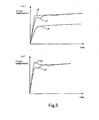
- Fig. 3 shows changes in the temperature of portions of the filter 18 while regeneration control for the filter 18 is effected.
- Fig. 3(a) shows changes in the temperature of an upstream portion of the filter 18, where curve L3 represents changes in the target temperature of that portion, that is, estimated changes in the temperature of that portion when the temperature rises with fuel addition through the fuel addition valve 17, curve L4 represents actual changes in the temperature of that portion in the case where there is no clogging of the oxidation catalyst 14, and curve L5 represents actual'changes in the temperature of that portion in the case where there is clogging of the oxidation catalyst 14.
- the quantity of heat generated by oxidation in the oxidation catalyst 14 decreases as described above, and the temperature of the exhaust gas flowing into the filter 18 decreases. Therefore, the temperature of the upstream portion of the filter 18 does not rise sufficiently to the target temperature. Particularly in the upstream portion of the filter 18 into which the exhaust gas flows, the temperature rise tends to be blunted due to flow of the exhaust gas. Consequently, there results a large difference in changes in the temperature of the upstream portion of the filter 18 between the case where there is clogging of the oxidation catalyst 14 and the case where there is not.
- Fig. 3(b) shows changes in the temperature of an downstream portion of the filter 18, where curve L6 represents actual changes in the temperature of that portion in the case where there is no clogging in the oxidation catalyst 14, and curve L7 represents actual changes in the temperature of that portion in the case where there is clogging of the oxidation catalyst 14.
- clogging of the oxidation catalyst 14 can be detected by examining the temperature of the exhaust gas flowing into the filter 18, which will affects the temperature of the upstream portion of the filter 18, and the temperature of the exhaust gas flowing out of the filter 18, which will affects the temperature of the downstream portion of the filter 18.
- Fig. 4 is a flow chart of a control process (which will be referred to as "oxidation catalyst clogging determination control" hereinafter) for determining clogging of the oxidation catalyst 14.
- the oxidation catalyst clogging determination control in this embodiment is a routine that is executed by the ECU 20 at a constant cycle.
- step S101 a determination is made as to whether or not regeneration control for the filter 18 is to be executed. Specifically, if the detection signal of the pressure difference sensor 33 indicates a pressure higher than or equal to a predetermined pressure, it is determined that the regeneration control is to be executed to oxidatively remove the particulate matter trapped on the filter 18. If it is determined that the regeneration control for the filter 18 is to be executed, the process proceeds to step S102. If it is determined that the regeneration control is not to be executed, this control routine is terminated.
- step S102 a determination is made as to whether or not the internal combustion engine 1 is in a steady running state.
- the steady running state refers to the running state in which significant changes in the engine load or the engine speed of the internal combustion engine 1 do not occur.
- the steady running state includes, for example, a constant speed running state in which deceleration or acceleration is not effected and an idling state.
- the reason why the determination is made as to whether or not the internal combustion engine 1 is in a steady state is that when the engine load or the engine speed of the internal combustion engine 1 changes significantly, the exhaust gas temperature also changes accordingly, and therefore it is difficult to determine clogging of the oxidation catalyst 14 based on the difference between the temperature of the exhaust gas flowing into the filter 18 and the temperature of the exhaust gas flowing out of the filter 18. If it is determined that the internal combustion engine 1 is in a steady running state, the process proceeds to step S103, and if it is determined that the internal combustion engine 1 is not in a steady running state, this control routine is terminated.
- step S103 a determination is made as to whether or not the difference between the temperature of the exhaust gas at the entrance of the filter 18 and a target temperature in the regeneration control for the filter 18 is smaller than a predetermined temperature difference ⁇ T1.
- the target temperature is a temperature to which the temperature of the filter 18 should be raised in order to oxidatively remove the particulate matter trapped, in the regeneration control for the filter 18.
- the temperature of the exhaust gas at the entrance of the filter 18 is estimated based on the temperature detected by the exhaust gas temperature sensor 31.
- the predetermined temperature difference ⁇ T1 is set as a temperature difference between the target temperature and the exhaust gas temperature at the entrance of the filter 18 in the regeneration control that can cause a determination error.
- step S104 a determination is made as to whether or not the temperature of the exhaust gas at the exit of the filter 18 is lower than a predetermined temperature T2.
- the temperature of the exhaust gas at the exit of the filter 18 is estimated based on the temperature detected by the exhaust gas temperature sensor 32.
- the reason why a determination is made as to whether or not the temperature of the exhaust gas at the exit of the filter 18 is lower than a predetermined temperature T2 is that if an excessive temperature rise occurs in the downstream portion of the filter 18, in which portion the temperature particularly rises in the regeneration control, there is a possibility that a determination error may be caused in determining clogging of the,oxidation catalyst 14 based on the difference between the temperature of the exhaust gas flowing into the filter 18 and the temperature of the exhaust gas flowing out of the filter as described above.
- the predetermined temperature T2 is set as a temperature of the exhaust gas at the exit of the filter 18 at the time when an excessive temperature rise of the filter 18 occurs.
- step S105 in order to determine clogging of the oxidation catalyst 14 based on the difference between the temperature of the exhaust gas flowing into the filter 18 and the temperature of the exhaust gas flowing out of the filter 18 as described above, a determination is made as to whether or not the difference between the temperature of the exhaust gas at the exit of the filter 18 estimated based on the temperature detected by the exhaust gas temperature sensor 32 and the temperature of the exhaust gas at the entrance of the filter 18 estimated based on the temperature detected by the exhaust gas temperature sensor 31 is larger than a predetermined temperature difference ⁇ T3.
- the predetermined temperature ⁇ T3 is the temperature difference that will be created when clogging of the oxidation catalyst 14 occurs. If it is determined that the aforementioned temperature difference is larger than the predetermined temperature ⁇ T3, the process proceeds to step S106. If it is determined that the temperature difference is not larger than the predetermined temperature ⁇ T3, this control routine is terminated.
- step S106 it is determined that there is clogging of the oxidation catalyst 14 based on the determination made in step S105.
- the ECU 20 that executes the process of steps S105 and S106 constitutes the clogging determination means in the present invention. After completion of step S106, this control routine is terminated.
- regeneration control for the filter 18 is effected in the state where there is clogging of the oxidation catalyst 14, it is possible that the regeneration control is not performed appropriately. This is because when there is clogging of the oxidation catalyst 14, the fuel added through the fuel addition valve 17 is not oxidized sufficiently.
- regeneration control for the filter 18 (which will be referred to as filter regeneration control) that is effected in the state in which there is clogging of the oxidation catalyst 14 will be described with reference to Fig. 5.
- step S201 the oxidation catalyst clogging determination control that has been described in connection with Fig. 4 is executed, so that a determination is made as to whether or not there is clogging of the oxidation catalyst 14.
- the regeneration control of the filter 18 differs between the case where there is clogging of the oxidation catalyst 14 and the case where there is not. Specifically, if it is determined that the oxidation catalyst 14 is in a clogged state, the process steps of S202 through S207 are executed, and if it is determined that the oxidation catalyst 14 is not in a clogging state, the process steps of S208 through S214 are executed.
- step S202 a target temperature to be reached for the downstream portion of the filter 18 is computed.
- the target temperature is a temperature to which the temperature of the filter 18 should be raised so as to oxidatively remove the particulate matter trapped on the filter 18 sufficiently.
- the reason why the reference of temperature rise in the regeneration control is made to the downstream portion of the filter 18 is that since when clogging occurs in the oxidation catalyst 14, the temperature of the exhaust gas flowing into the filter 18 decreases and the temperature of the upstream portion of the filter 18 is not raised sufficiently (see curve L5 in Fig. 3(a)), if the reference is to the upstream portion, there is a risk that the time required for the regeneration control will be needlessly prolonged.
- step S203 the quantity of fuel to be added through the fuel addition valve 17 is computed.
- the quantity of the fuel to be added is not determined by a feedback control based on the difference between the target temperature computed in step S202 and the current temperature of the downstream portion of the filter 18 estimated by the exhaust gas temperature sensor 32, but it is determined based on a two-dimensional map that has as parameters the target temperature to be reached and the temperature of the downstream portion of the filter 18. In connection with this, depending on the type of the two-dimensional map, a fuel addition quantity may be computed taking into account a decrease in the oxidation heat caused by clogging of the oxidation catalyst 14. After completion of step S203, the process proceeds to step S204.
- step S204 fuel is added to the exhaust gas through the fuel addition valve 17 in accordance with the fuel addition quantity computed in step S203.
- the temperature of the filter 18 is raised and oxidative removal of the particulate matter trapped is performed.
- step S205 the amount of the particulate matter remaining on the filter 18 is calculated based on the temperature of the downstream portion of the filter 18, taking into account the amount of the particulate matter (PM) that has been oxidatively removed by the regeneration control.
- the ECU 20 that executes the process of calculating the amount of the remaining particulate matter constitutes the deposit amount estimation means in the present invention.
- the process of calculating the amount of the remaining particulate matter executed in step S211 that will be described later is the same as this process.
- step S205 the process proceeds to step S206.
- step S206 a determination is made as to whether or not the amount of the remaining particulate matter calculated in step S205 is smaller than a predetermined amount PM0.
- the predetermined amount PM0 is the threshold value for determining to terminate the regeneration process for the filter 18. If it is determined that the amount of the remaining particulate matter is smaller than the predetermined amount PM0, the process proceeds to step S207, where the regeneration control for the filter 18 is terminated, and then this process routine is ended. If it is determined that the amount of the remaining particulate matter is not smaller than the predetermined amount PM0, the process step of S203 and the subsequent steps are repeated.
- step S208 a target temperature to be reached for the upstream portion of the filter 18 is computed.
- the reason why the reference of temperature rise in the regeneration control is made to the upstream portion of the filter 18 is that since the temperature of the upstream portion of the filter 18 is relatively low as compared to the downstream portion due to inflowing of the exhaust gas, when the reference is made in the regeneration control to the temperature of the upstream portion that has a relatively low temperature, it is possible to raise the temperature of the filter 18 as a whole sufficiently.
- step S208 the process proceeds to step S209.
- step S209 the quantity of fuel to be added through the fuel addition valve 17 is computed.
- the quantity of the fuel to be added is determined by a feedback control based on the difference between the target temperature computed in step S208 and the current temperature of the upstream portion of the filter 18 estimated by the exhaust gas temperature sensor 32. Since a decrease in the temperature of the exhaust gas caused by clogging of the oxidation catalyst 14 as described above does not occur, there is no risk that the fuel addition amount will be excessively increased by performing the feedback control.
- step S210 the process proceeds to step S210.
- step S210 fuel is added to the exhaust gas through the fuel addition valve 17 in accordance with the fuel addition quantity computed in step S209.
- the temperature of the filter 18 is raised and oxidative removal of the particulate matter trapped is performed.
- step S211 the amount of the particulate matter remaining on the filter 18 is calculated based on the temperature of the upstream portion of the filter 18, taking into account the amount of the particulate matter (PM) that has been oxidatively removed by the regeneration control.
- the reason why the calculation is performed on the basis of the temperature of the downstream portion of the filter 18 contrary to step 205 is that since a decrease in the temperature of the exhaust gas caused by clogging of the oxidation catalyst 14 as described above does not occur, it is possible to calculate the amount of the particulate matter that has been oxidatively removed accurately on the basis of the temperature of the upstream portion of the filter 18, and in addition consistency of the process with steps S208 and S209 should be maintained.
- step S212 the process proceeds to step S212.
- step S212 a determination is made as to whether or not the fuel addition valve 17 is clogged.
- the ECU 20 that executes determination of clogging of the fuel addition valve 17 constitutes the fuel supply appropriateness determination means in the present invention. Specifically, a determination is made as to whether or not a quantity of fuel to be added to the exhaust gas has been appropriately added, based on the relationship between the quantity of fuel to be added through the fuel addition valve 17 and the temperature of the upstream portion of the filter 18, namely the relationship between the quantity of fuel to be added through the fuel addition valve 17 and the oxidation heat quantity in the oxidation catalyst 14. Such a determination is not made in the process for the case where the oxidation catalyst 14 is in a clogged state (steps S202 through S207). This is because when the oxidation catalyst 14 is in a clogged state, a determination error can occur, since the oxidation catalyst 14 cannot oxidize the added fuel sufficiently.
- step S213 a determination is made as to whether or not the amount of the remaining particulate matter calculated in step S211 is smaller than a predetermined amount PM0. If it is determined that the amount of the remaining particulate matter is smaller than the predetermined amount PM0, the process proceeds to step S214, where the regeneration control for the filter 18 is terminated, and then this process routine is ended. If it is determined that the amount of the remaining particulate matter is not smaller than the predetermined amount PM0, the process step of S209 and the subsequent steps are repeated.
- the regeneration control of the filter 18 differs between the case where there is clogging of the oxidation catalyst 14 and the case where there is not. Specifically, when the oxidation catalyst 14 is in a clogged state, each processing is effected basically on the basis of the temperature of the downstream portion of the filter 18, and feedback control of the fuel addition quantity and determination of clogging of the fuel addition valve 17 are prohibited. Thus, the time required for regeneration control for the filter 18 can be made as short as possible, and it is possible to prevent erroneous control of fuel addition and an error in determining clogging of the fuel addition valve 17.
- An exhaust gas purifying system for an internal combustion engine comprises an oxidation catalyst having an oxidizing ability, provided in an exhaust passage of an internal combustion engine, a filter that can trap particulate matter contained in exhaust gas, provided in the exhaust passage downstream of said oxidation catalyst, temperature detection means for detecting or estimating temperatures of an upstream portion and a downstream portion of said filter, fuel supply means for supplying fuel into exhaust gas flowing into said oxidation catalyst, and clogging determination means adapted to make such a determination that there is clogging of said oxidation catalyst, if the difference in the temperature of the upstream portion and the temperature of the downstream portion detected by said temperature detection means is larger than a predetermined value while regeneration control for said filter is performed by supplying fuel to exhaust gas flowing into said oxidation catalyst by said fuel supply means.
- the exhaust gas purifying system for an internal combustion engine having an oxidation catalyst and a filter provided in series in an exhaust passage as per the above, it is possible to determine clogging of the oxidation catalyst with improved accuracy.
Landscapes
- Engineering & Computer Science (AREA)
- Chemical & Material Sciences (AREA)
- Combustion & Propulsion (AREA)
- Mechanical Engineering (AREA)
- General Engineering & Computer Science (AREA)
- Chemical Kinetics & Catalysis (AREA)
- Health & Medical Sciences (AREA)
- Toxicology (AREA)
- Processes For Solid Components From Exhaust (AREA)
- Exhaust Gas After Treatment (AREA)
Applications Claiming Priority (1)
| Application Number | Priority Date | Filing Date | Title |
|---|---|---|---|
| JP2004355508A JP2006161718A (ja) | 2004-12-08 | 2004-12-08 | 内燃機関の排気浄化システム |
Publications (2)
| Publication Number | Publication Date |
|---|---|
| EP1669565A1 true EP1669565A1 (fr) | 2006-06-14 |
| EP1669565B1 EP1669565B1 (fr) | 2007-04-04 |
Family
ID=35501058
Family Applications (1)
| Application Number | Title | Priority Date | Filing Date |
|---|---|---|---|
| EP05026721A Expired - Lifetime EP1669565B1 (fr) | 2004-12-08 | 2005-12-07 | Dispositif de purification de gaz d'échappement pour moteur à combustion interne |
Country Status (3)
| Country | Link |
|---|---|
| EP (1) | EP1669565B1 (fr) |
| JP (1) | JP2006161718A (fr) |
| DE (1) | DE602005000814T2 (fr) |
Cited By (12)
| Publication number | Priority date | Publication date | Assignee | Title |
|---|---|---|---|---|
| WO2009144428A1 (fr) * | 2008-05-30 | 2009-12-03 | Peugeot Citroën Automobiles SA | Procede et dispositif de reconnaissance d'une combustion dans un filtre a particules |
| EP2143918A1 (fr) * | 2008-07-11 | 2010-01-13 | Perkins Engines Company Limited | Système de décontamination post-traitement |
| US20100076666A1 (en) * | 2008-09-19 | 2010-03-25 | Gm Global Technology Operations, Inc. | Temperature control system and method for particulate filter regeneration using a hydrocarbon injector |
| CN102084095A (zh) * | 2008-07-25 | 2011-06-01 | 标致·雪铁龙汽车公司 | 颗粒过滤器温度调节的适应方法 |
| CN102549246A (zh) * | 2010-05-17 | 2012-07-04 | 丰田自动车株式会社 | 用于废气排放控制设备的异常检测设备 |
| WO2012172423A1 (fr) * | 2011-06-17 | 2012-12-20 | Toyota Jidosha Kabushiki Kaisha | Dispositif de traitement des gaz d'échappement pour moteur à combustion interne |
| US8561393B2 (en) | 2011-03-21 | 2013-10-22 | GM Global Technology Operations LLC | Method of determining if an oxidation catalyst is quenched or is not quenched |
| FR3026431A1 (fr) * | 2014-09-29 | 2016-04-01 | Peugeot Citroen Automobiles Sa | Procede de recalage de l'estimation de particules de suie dans un filtre a particules d'un vehicule automobile |
| CN109578123A (zh) * | 2018-11-27 | 2019-04-05 | 潍柴动力股份有限公司 | 一种柴油机氧化催化器失效判定方法及装置 |
| EP3460211A4 (fr) * | 2016-06-30 | 2019-05-15 | Mitsubishi Heavy Industries Engine & Turbocharger, Ltd. | Dispositif de commande de régénération destiné à un dispositif de traitement de gaz d'échappement |
| DE112007001627B4 (de) * | 2006-07-12 | 2021-06-24 | Cummins Filtration Inc. | Systeme, Vorrichtungen und Verfahren zur Bestimmung eines Zusetzens oder Reinigens einer Diesel-Oxidationskatalysatoreinrichtung |
| CN114183225A (zh) * | 2021-11-23 | 2022-03-15 | 潍柴动力股份有限公司 | 排气管温降检测方法及装置 |
Families Citing this family (8)
| Publication number | Priority date | Publication date | Assignee | Title |
|---|---|---|---|---|
| DE102007011487A1 (de) * | 2007-03-07 | 2008-09-11 | Emitec Gesellschaft Für Emissionstechnologie Mbh | Verfahren zur Überwachung der Funktionsfähigkeit eines Partikelfilters, sowie entsprechendes Abgassystem |
| JP4530081B2 (ja) * | 2008-07-25 | 2010-08-25 | トヨタ自動車株式会社 | 内燃機関の触媒劣化診断装置及び触媒劣化診断方法 |
| US9181843B2 (en) * | 2011-09-26 | 2015-11-10 | GM Global Technology Operations LLC | On-board diagnostic method for NO2 formation in an oxidation catalyst |
| GB2510171B (en) * | 2013-01-28 | 2015-01-28 | Cool Flame Technologies As | Method and cleaning apparatus for removal of SOx and NOx from exhaust gas |
| DE102015002464A1 (de) * | 2015-02-27 | 2016-09-01 | Daimler Ag | Verfahren zur Diagnose einer Abgasnachbehandlungseinrichtung einer Verbrennungskraftmaschine |
| EP3184769B1 (fr) * | 2015-12-25 | 2018-07-18 | Kubota Corporation | Dispositif d'échappement pour moteur diesel |
| JP6642199B2 (ja) * | 2016-03-30 | 2020-02-05 | 三菱自動車工業株式会社 | 排気浄化装置 |
| JP2022180939A (ja) | 2021-05-25 | 2022-12-07 | 株式会社豊田自動織機 | 排気浄化システム |
Citations (5)
| Publication number | Priority date | Publication date | Assignee | Title |
|---|---|---|---|---|
| EP0815925A1 (fr) * | 1996-07-04 | 1998-01-07 | Toyota Jidosha Kabushiki Kaisha | Appareil pour purifier les gaz d'échappement d'un moteur Diesel |
| US20040035101A1 (en) * | 2001-06-26 | 2004-02-26 | Takehito Imai | Regenerative control method for continuous regenerative diesel particulate filter device |
| JP2004239074A (ja) * | 2003-02-03 | 2004-08-26 | Hino Motors Ltd | 排気浄化装置 |
| JP2004278396A (ja) * | 2003-03-14 | 2004-10-07 | Sakura Shokai:Kk | 排気ガスの浄化装置 |
| DE102004019659A1 (de) * | 2003-04-25 | 2004-12-02 | Mitsubishi Fuso Truck And Bus Corp. | Abgasemissions-Steuervorrichtung für einen Verbrennungsmotor |
Family Cites Families (5)
| Publication number | Priority date | Publication date | Assignee | Title |
|---|---|---|---|---|
| JP3767483B2 (ja) * | 2002-01-08 | 2006-04-19 | 日産自動車株式会社 | 内燃機関の排気浄化装置 |
| JP2003214145A (ja) * | 2002-01-21 | 2003-07-30 | Hino Motors Ltd | パティキュレートフィルタの再生方法 |
| JP4012037B2 (ja) * | 2002-10-23 | 2007-11-21 | 日野自動車株式会社 | 排気浄化装置 |
| JP2004300973A (ja) * | 2003-03-31 | 2004-10-28 | Isuzu Motors Ltd | Dpfの再生開始判定方法及びdpfを備えた排気ガス浄化システム |
| JP4311071B2 (ja) * | 2003-04-23 | 2009-08-12 | トヨタ自動車株式会社 | 排気浄化システムの不具合判定方法 |
-
2004
- 2004-12-08 JP JP2004355508A patent/JP2006161718A/ja active Pending
-
2005
- 2005-12-07 EP EP05026721A patent/EP1669565B1/fr not_active Expired - Lifetime
- 2005-12-07 DE DE602005000814T patent/DE602005000814T2/de not_active Expired - Fee Related
Patent Citations (5)
| Publication number | Priority date | Publication date | Assignee | Title |
|---|---|---|---|---|
| EP0815925A1 (fr) * | 1996-07-04 | 1998-01-07 | Toyota Jidosha Kabushiki Kaisha | Appareil pour purifier les gaz d'échappement d'un moteur Diesel |
| US20040035101A1 (en) * | 2001-06-26 | 2004-02-26 | Takehito Imai | Regenerative control method for continuous regenerative diesel particulate filter device |
| JP2004239074A (ja) * | 2003-02-03 | 2004-08-26 | Hino Motors Ltd | 排気浄化装置 |
| JP2004278396A (ja) * | 2003-03-14 | 2004-10-07 | Sakura Shokai:Kk | 排気ガスの浄化装置 |
| DE102004019659A1 (de) * | 2003-04-25 | 2004-12-02 | Mitsubishi Fuso Truck And Bus Corp. | Abgasemissions-Steuervorrichtung für einen Verbrennungsmotor |
Non-Patent Citations (1)
| Title |
|---|
| PATENT ABSTRACTS OF JAPAN vol. 2003, no. 12 5 December 2003 (2003-12-05) * |
Cited By (24)
| Publication number | Priority date | Publication date | Assignee | Title |
|---|---|---|---|---|
| DE112007001627B4 (de) * | 2006-07-12 | 2021-06-24 | Cummins Filtration Inc. | Systeme, Vorrichtungen und Verfahren zur Bestimmung eines Zusetzens oder Reinigens einer Diesel-Oxidationskatalysatoreinrichtung |
| WO2009144428A1 (fr) * | 2008-05-30 | 2009-12-03 | Peugeot Citroën Automobiles SA | Procede et dispositif de reconnaissance d'une combustion dans un filtre a particules |
| FR2931879A1 (fr) * | 2008-05-30 | 2009-12-04 | Peugeot Citroen Automobiles Sa | Procede et dispositif de reconnaissance d'une combustion dans un filtre a particules |
| CN102046936A (zh) * | 2008-05-30 | 2011-05-04 | 标致·雪铁龙汽车公司 | 识别颗粒过滤器中的燃烧情况的方法和装置 |
| RU2484266C2 (ru) * | 2008-05-30 | 2013-06-10 | Пежо Ситроен Отомобиль Са | Способ и устройство для распознавания сгорания в фильтре частиц |
| EP2143918A1 (fr) * | 2008-07-11 | 2010-01-13 | Perkins Engines Company Limited | Système de décontamination post-traitement |
| US20100005784A1 (en) * | 2008-07-11 | 2010-01-14 | Caterpillar Inc. | After-Treatment De-Contamination System |
| US8534045B2 (en) * | 2008-07-11 | 2013-09-17 | Perkins Engines Company Limited | After-treatment de-contamination system |
| CN102084095A (zh) * | 2008-07-25 | 2011-06-01 | 标致·雪铁龙汽车公司 | 颗粒过滤器温度调节的适应方法 |
| CN102084095B (zh) * | 2008-07-25 | 2013-06-12 | 标致·雪铁龙汽车公司 | 颗粒过滤器温度调节的适应方法 |
| US20100076666A1 (en) * | 2008-09-19 | 2010-03-25 | Gm Global Technology Operations, Inc. | Temperature control system and method for particulate filter regeneration using a hydrocarbon injector |
| US8265852B2 (en) * | 2008-09-19 | 2012-09-11 | GM Global Technology Operations LLC | Temperature control system and method for particulate filter regeneration using a hydrocarbon injector |
| CN102549246B (zh) * | 2010-05-17 | 2013-09-04 | 丰田自动车株式会社 | 用于废气排放控制设备的异常检测设备 |
| CN102549246A (zh) * | 2010-05-17 | 2012-07-04 | 丰田自动车株式会社 | 用于废气排放控制设备的异常检测设备 |
| US8561393B2 (en) | 2011-03-21 | 2013-10-22 | GM Global Technology Operations LLC | Method of determining if an oxidation catalyst is quenched or is not quenched |
| WO2012172423A1 (fr) * | 2011-06-17 | 2012-12-20 | Toyota Jidosha Kabushiki Kaisha | Dispositif de traitement des gaz d'échappement pour moteur à combustion interne |
| AU2012270014B2 (en) * | 2011-06-17 | 2015-07-23 | Kabushiki Kaisha Toyota Jidoshokki | Exhaust gas control apparatus for internal combustion engine |
| FR3026431A1 (fr) * | 2014-09-29 | 2016-04-01 | Peugeot Citroen Automobiles Sa | Procede de recalage de l'estimation de particules de suie dans un filtre a particules d'un vehicule automobile |
| EP3460211A4 (fr) * | 2016-06-30 | 2019-05-15 | Mitsubishi Heavy Industries Engine & Turbocharger, Ltd. | Dispositif de commande de régénération destiné à un dispositif de traitement de gaz d'échappement |
| US10871095B2 (en) | 2016-06-30 | 2020-12-22 | Mitsubishi Heavy Industries Engine & Turbocharger, Ltd. | Regeneration control device for exhaust gas treatment device |
| CN109578123A (zh) * | 2018-11-27 | 2019-04-05 | 潍柴动力股份有限公司 | 一种柴油机氧化催化器失效判定方法及装置 |
| CN109578123B (zh) * | 2018-11-27 | 2020-06-26 | 潍柴动力股份有限公司 | 一种柴油机氧化催化器失效判定方法及装置 |
| CN114183225A (zh) * | 2021-11-23 | 2022-03-15 | 潍柴动力股份有限公司 | 排气管温降检测方法及装置 |
| CN114183225B (zh) * | 2021-11-23 | 2022-10-25 | 潍柴动力股份有限公司 | 排气管温降检测方法及装置 |
Also Published As
| Publication number | Publication date |
|---|---|
| DE602005000814D1 (de) | 2007-05-16 |
| DE602005000814T2 (de) | 2008-01-10 |
| EP1669565B1 (fr) | 2007-04-04 |
| JP2006161718A (ja) | 2006-06-22 |
Similar Documents
| Publication | Publication Date | Title |
|---|---|---|
| EP1669565B1 (fr) | Dispositif de purification de gaz d'échappement pour moteur à combustion interne | |
| EP1882088B1 (fr) | Systeme de purification des gaz d'echappement destine a un moteur a combustion interne | |
| US8074442B2 (en) | Method of determining abnormality in particulate filter | |
| JP4430704B2 (ja) | 内燃機関の排気浄化装置 | |
| US8037675B2 (en) | Exhaust gas purification system for internal combustion engine and method for exhaust gas purification | |
| US6983591B2 (en) | Particulate filter regenerating device | |
| EP1455060B1 (fr) | Dispositif de purification des gaz d'échappement d'un moteur | |
| JP5168089B2 (ja) | 触媒の診断装置 | |
| EP1725752B1 (fr) | Controleur de regeneration pour appareil de purification des gaz d'echappement dans un moteur a combustion interne | |
| EP1723322B1 (fr) | Controleur de regeneration pour appareil de purification d'echappement d'un moteur a combustion interne | |
| US20090044517A1 (en) | Exhaust gas purification system for an internal combustion engine | |
| JP2009281144A (ja) | 過給機付き内燃機関の制御装置 | |
| EP1515017B1 (fr) | Dispositif de contrôle d'un catalyseur pour un moteur à combustion interne | |
| EP2211044B1 (fr) | Contrôleur EGR et procédé de contrôle EGR pour moteur à combustion interne | |
| JP2005240719A (ja) | フィルタの再生時期検出装置およびフィルタの再生制御装置 | |
| US11536209B2 (en) | Control device, engine, and control method of engine | |
| JP2006316746A (ja) | 内燃機関の排ガス浄化装置 | |
| US20070256408A1 (en) | Particulate Matter Remaining Amount Estimating Method for Particulate Filter and Particulate Filter Regenerating Method | |
| JP2009121362A (ja) | 内燃機関のフィルタ再生制御装置 | |
| EP1471219B1 (fr) | Système d'épuration de gaz d'échappement et procédé de décontamination d'un moteur contaminé au soufre | |
| EP1515029B1 (fr) | Système de purification des gaz d'échappement pour un moteur à combustion interne | |
| EP1722088B1 (fr) | Système de traitement des gaz d'échappement d'un moteur à combustion interne | |
| JP4333230B2 (ja) | 内燃機関の排気浄化システム | |
| JP4556800B2 (ja) | エンジンの背圧制御装置 | |
| EP1650414B1 (fr) | Dispositif de contrôle de gas d'échappement pour moteur à combustion interne |
Legal Events
| Date | Code | Title | Description |
|---|---|---|---|
| PUAI | Public reference made under article 153(3) epc to a published international application that has entered the european phase |
Free format text: ORIGINAL CODE: 0009012 |
|
| 17P | Request for examination filed |
Effective date: 20051207 |
|
| AK | Designated contracting states |
Kind code of ref document: A1 Designated state(s): AT BE BG CH CY CZ DE DK EE ES FI FR GB GR HU IE IS IT LI LT LU LV MC NL PL PT RO SE SI SK TR |
|
| AX | Request for extension of the european patent |
Extension state: AL BA HR MK YU |
|
| GRAP | Despatch of communication of intention to grant a patent |
Free format text: ORIGINAL CODE: EPIDOSNIGR1 |
|
| GRAC | Information related to communication of intention to grant a patent modified |
Free format text: ORIGINAL CODE: EPIDOSCIGR1 |
|
| GRAS | Grant fee paid |
Free format text: ORIGINAL CODE: EPIDOSNIGR3 |
|
| AKX | Designation fees paid |
Designated state(s): DE FR GB |
|
| GRAA | (expected) grant |
Free format text: ORIGINAL CODE: 0009210 |
|
| AK | Designated contracting states |
Kind code of ref document: B1 Designated state(s): DE FR GB |
|
| REG | Reference to a national code |
Ref country code: GB Ref legal event code: FG4D |
|
| REF | Corresponds to: |
Ref document number: 602005000814 Country of ref document: DE Date of ref document: 20070516 Kind code of ref document: P |
|
| ET | Fr: translation filed | ||
| PLBE | No opposition filed within time limit |
Free format text: ORIGINAL CODE: 0009261 |
|
| STAA | Information on the status of an ep patent application or granted ep patent |
Free format text: STATUS: NO OPPOSITION FILED WITHIN TIME LIMIT |
|
| 26N | No opposition filed |
Effective date: 20080107 |
|
| PGFP | Annual fee paid to national office [announced via postgrant information from national office to epo] |
Ref country code: FR Payment date: 20081212 Year of fee payment: 4 |
|
| PGFP | Annual fee paid to national office [announced via postgrant information from national office to epo] |
Ref country code: DE Payment date: 20081205 Year of fee payment: 4 |
|
| GBPC | Gb: european patent ceased through non-payment of renewal fee |
Effective date: 20091207 |
|
| REG | Reference to a national code |
Ref country code: FR Ref legal event code: ST Effective date: 20100831 |
|
| PG25 | Lapsed in a contracting state [announced via postgrant information from national office to epo] |
Ref country code: FR Free format text: LAPSE BECAUSE OF NON-PAYMENT OF DUE FEES Effective date: 20091231 |
|
| PG25 | Lapsed in a contracting state [announced via postgrant information from national office to epo] |
Ref country code: DE Free format text: LAPSE BECAUSE OF NON-PAYMENT OF DUE FEES Effective date: 20100701 |
|
| PG25 | Lapsed in a contracting state [announced via postgrant information from national office to epo] |
Ref country code: GB Free format text: LAPSE BECAUSE OF NON-PAYMENT OF DUE FEES Effective date: 20091207 |