EP1669568A1 - Echangeur de chaleur de gaz d'échappement pour un système de cogénération - Google Patents
Echangeur de chaleur de gaz d'échappement pour un système de cogénération Download PDFInfo
- Publication number
- EP1669568A1 EP1669568A1 EP05026968A EP05026968A EP1669568A1 EP 1669568 A1 EP1669568 A1 EP 1669568A1 EP 05026968 A EP05026968 A EP 05026968A EP 05026968 A EP05026968 A EP 05026968A EP 1669568 A1 EP1669568 A1 EP 1669568A1
- Authority
- EP
- European Patent Office
- Prior art keywords
- exhaust gas
- heat exchanger
- shell
- gas discharge
- tube portion
- Prior art date
- Legal status (The legal status is an assumption and is not a legal conclusion. Google has not performed a legal analysis and makes no representation as to the accuracy of the status listed.)
- Withdrawn
Links
Images



Classifications
-
- F—MECHANICAL ENGINEERING; LIGHTING; HEATING; WEAPONS; BLASTING
- F01—MACHINES OR ENGINES IN GENERAL; ENGINE PLANTS IN GENERAL; STEAM ENGINES
- F01N—GAS-FLOW SILENCERS OR EXHAUST APPARATUS FOR MACHINES OR ENGINES IN GENERAL; GAS-FLOW SILENCERS OR EXHAUST APPARATUS FOR INTERNAL-COMBUSTION ENGINES
- F01N3/00—Exhaust or silencing apparatus having means for purifying, rendering innocuous, or otherwise treating exhaust
- F01N3/02—Exhaust or silencing apparatus having means for purifying, rendering innocuous, or otherwise treating exhaust for cooling, or for removing solid constituents of, exhaust
- F01N3/04—Exhaust or silencing apparatus having means for purifying, rendering innocuous, or otherwise treating exhaust for cooling, or for removing solid constituents of, exhaust using liquids
- F01N3/043—Exhaust or silencing apparatus having means for purifying, rendering innocuous, or otherwise treating exhaust for cooling, or for removing solid constituents of, exhaust using liquids without contact between liquid and exhaust gases
-
- F—MECHANICAL ENGINEERING; LIGHTING; HEATING; WEAPONS; BLASTING
- F01—MACHINES OR ENGINES IN GENERAL; ENGINE PLANTS IN GENERAL; STEAM ENGINES
- F01N—GAS-FLOW SILENCERS OR EXHAUST APPARATUS FOR MACHINES OR ENGINES IN GENERAL; GAS-FLOW SILENCERS OR EXHAUST APPARATUS FOR INTERNAL-COMBUSTION ENGINES
- F01N3/00—Exhaust or silencing apparatus having means for purifying, rendering innocuous, or otherwise treating exhaust
- F01N3/08—Exhaust or silencing apparatus having means for purifying, rendering innocuous, or otherwise treating exhaust for rendering innocuous
- F01N3/10—Exhaust or silencing apparatus having means for purifying, rendering innocuous, or otherwise treating exhaust for rendering innocuous by thermal or catalytic conversion of noxious components of exhaust
- F01N3/18—Exhaust or silencing apparatus having means for purifying, rendering innocuous, or otherwise treating exhaust for rendering innocuous by thermal or catalytic conversion of noxious components of exhaust characterised by methods of operation; Control
- F01N3/20—Exhaust or silencing apparatus having means for purifying, rendering innocuous, or otherwise treating exhaust for rendering innocuous by thermal or catalytic conversion of noxious components of exhaust characterised by methods of operation; Control specially adapted for catalytic conversion
- F01N3/2006—Periodically heating or cooling catalytic reactors, e.g. at cold starting or overheating
- F01N3/2046—Periodically cooling catalytic reactors
-
- F—MECHANICAL ENGINEERING; LIGHTING; HEATING; WEAPONS; BLASTING
- F01—MACHINES OR ENGINES IN GENERAL; ENGINE PLANTS IN GENERAL; STEAM ENGINES
- F01N—GAS-FLOW SILENCERS OR EXHAUST APPARATUS FOR MACHINES OR ENGINES IN GENERAL; GAS-FLOW SILENCERS OR EXHAUST APPARATUS FOR INTERNAL-COMBUSTION ENGINES
- F01N3/00—Exhaust or silencing apparatus having means for purifying, rendering innocuous, or otherwise treating exhaust
- F01N3/08—Exhaust or silencing apparatus having means for purifying, rendering innocuous, or otherwise treating exhaust for rendering innocuous
- F01N3/10—Exhaust or silencing apparatus having means for purifying, rendering innocuous, or otherwise treating exhaust for rendering innocuous by thermal or catalytic conversion of noxious components of exhaust
- F01N3/24—Exhaust or silencing apparatus having means for purifying, rendering innocuous, or otherwise treating exhaust for rendering innocuous by thermal or catalytic conversion of noxious components of exhaust characterised by constructional aspects of converting apparatus
- F01N3/28—Construction of catalytic reactors
- F01N3/2882—Catalytic reactors combined or associated with other devices, e.g. exhaust silencers or other exhaust purification devices
- F01N3/2889—Catalytic reactors combined or associated with other devices, e.g. exhaust silencers or other exhaust purification devices with heat exchangers in a single housing
-
- F—MECHANICAL ENGINEERING; LIGHTING; HEATING; WEAPONS; BLASTING
- F01—MACHINES OR ENGINES IN GENERAL; ENGINE PLANTS IN GENERAL; STEAM ENGINES
- F01N—GAS-FLOW SILENCERS OR EXHAUST APPARATUS FOR MACHINES OR ENGINES IN GENERAL; GAS-FLOW SILENCERS OR EXHAUST APPARATUS FOR INTERNAL-COMBUSTION ENGINES
- F01N5/00—Exhaust or silencing apparatus combined or associated with devices profiting by exhaust energy
- F01N5/02—Exhaust or silencing apparatus combined or associated with devices profiting by exhaust energy the devices using heat
-
- F—MECHANICAL ENGINEERING; LIGHTING; HEATING; WEAPONS; BLASTING
- F28—HEAT EXCHANGE IN GENERAL
- F28D—HEAT-EXCHANGE APPARATUS, NOT PROVIDED FOR IN ANOTHER SUBCLASS, IN WHICH THE HEAT-EXCHANGE MEDIA DO NOT COME INTO DIRECT CONTACT
- F28D7/00—Heat-exchange apparatus having stationary tubular conduit assemblies for both heat-exchange media, the media being in contact with different sides of a conduit wall
-
- F—MECHANICAL ENGINEERING; LIGHTING; HEATING; WEAPONS; BLASTING
- F28—HEAT EXCHANGE IN GENERAL
- F28D—HEAT-EXCHANGE APPARATUS, NOT PROVIDED FOR IN ANOTHER SUBCLASS, IN WHICH THE HEAT-EXCHANGE MEDIA DO NOT COME INTO DIRECT CONTACT
- F28D7/00—Heat-exchange apparatus having stationary tubular conduit assemblies for both heat-exchange media, the media being in contact with different sides of a conduit wall
- F28D7/10—Heat-exchange apparatus having stationary tubular conduit assemblies for both heat-exchange media, the media being in contact with different sides of a conduit wall the conduits being arranged one within the other, e.g. concentrically
-
- F—MECHANICAL ENGINEERING; LIGHTING; HEATING; WEAPONS; BLASTING
- F28—HEAT EXCHANGE IN GENERAL
- F28D—HEAT-EXCHANGE APPARATUS, NOT PROVIDED FOR IN ANOTHER SUBCLASS, IN WHICH THE HEAT-EXCHANGE MEDIA DO NOT COME INTO DIRECT CONTACT
- F28D7/00—Heat-exchange apparatus having stationary tubular conduit assemblies for both heat-exchange media, the media being in contact with different sides of a conduit wall
- F28D7/16—Heat-exchange apparatus having stationary tubular conduit assemblies for both heat-exchange media, the media being in contact with different sides of a conduit wall the conduits being arranged in parallel spaced relation
- F28D7/1607—Heat-exchange apparatus having stationary tubular conduit assemblies for both heat-exchange media, the media being in contact with different sides of a conduit wall the conduits being arranged in parallel spaced relation with particular pattern of flow of the heat exchange media, e.g. change of flow direction
-
- F—MECHANICAL ENGINEERING; LIGHTING; HEATING; WEAPONS; BLASTING
- F28—HEAT EXCHANGE IN GENERAL
- F28F—DETAILS OF HEAT-EXCHANGE AND HEAT-TRANSFER APPARATUS, OF GENERAL APPLICATION
- F28F1/00—Tubular elements; Assemblies of tubular elements
- F28F1/02—Tubular elements of cross-section which is non-circular
- F28F1/06—Tubular elements of cross-section which is non-circular crimped or corrugated in cross-section
-
- F—MECHANICAL ENGINEERING; LIGHTING; HEATING; WEAPONS; BLASTING
- F28—HEAT EXCHANGE IN GENERAL
- F28F—DETAILS OF HEAT-EXCHANGE AND HEAT-TRANSFER APPARATUS, OF GENERAL APPLICATION
- F28F1/00—Tubular elements; Assemblies of tubular elements
- F28F1/08—Tubular elements crimped or corrugated in longitudinal section
-
- F—MECHANICAL ENGINEERING; LIGHTING; HEATING; WEAPONS; BLASTING
- F01—MACHINES OR ENGINES IN GENERAL; ENGINE PLANTS IN GENERAL; STEAM ENGINES
- F01N—GAS-FLOW SILENCERS OR EXHAUST APPARATUS FOR MACHINES OR ENGINES IN GENERAL; GAS-FLOW SILENCERS OR EXHAUST APPARATUS FOR INTERNAL-COMBUSTION ENGINES
- F01N2240/00—Combination or association of two or more different exhaust treating devices, or of at least one such device with an auxiliary device, not covered by indexing codes F01N2230/00 or F01N2250/00, one of the devices being
- F01N2240/02—Combination or association of two or more different exhaust treating devices, or of at least one such device with an auxiliary device, not covered by indexing codes F01N2230/00 or F01N2250/00, one of the devices being a heat exchanger
-
- F—MECHANICAL ENGINEERING; LIGHTING; HEATING; WEAPONS; BLASTING
- F01—MACHINES OR ENGINES IN GENERAL; ENGINE PLANTS IN GENERAL; STEAM ENGINES
- F01N—GAS-FLOW SILENCERS OR EXHAUST APPARATUS FOR MACHINES OR ENGINES IN GENERAL; GAS-FLOW SILENCERS OR EXHAUST APPARATUS FOR INTERNAL-COMBUSTION ENGINES
- F01N2260/00—Exhaust treating devices having provisions not otherwise provided for
- F01N2260/02—Exhaust treating devices having provisions not otherwise provided for for cooling the device
- F01N2260/024—Exhaust treating devices having provisions not otherwise provided for for cooling the device using a liquid
-
- F—MECHANICAL ENGINEERING; LIGHTING; HEATING; WEAPONS; BLASTING
- F01—MACHINES OR ENGINES IN GENERAL; ENGINE PLANTS IN GENERAL; STEAM ENGINES
- F01N—GAS-FLOW SILENCERS OR EXHAUST APPARATUS FOR MACHINES OR ENGINES IN GENERAL; GAS-FLOW SILENCERS OR EXHAUST APPARATUS FOR INTERNAL-COMBUSTION ENGINES
- F01N2260/00—Exhaust treating devices having provisions not otherwise provided for
- F01N2260/10—Exhaust treating devices having provisions not otherwise provided for for avoiding stress caused by expansions or contractions due to temperature variations
-
- F—MECHANICAL ENGINEERING; LIGHTING; HEATING; WEAPONS; BLASTING
- F01—MACHINES OR ENGINES IN GENERAL; ENGINE PLANTS IN GENERAL; STEAM ENGINES
- F01N—GAS-FLOW SILENCERS OR EXHAUST APPARATUS FOR MACHINES OR ENGINES IN GENERAL; GAS-FLOW SILENCERS OR EXHAUST APPARATUS FOR INTERNAL-COMBUSTION ENGINES
- F01N2470/00—Structure or shape of exhaust gas passages, pipes or tubes
- F01N2470/10—Tubes having non-circular cross section
-
- F—MECHANICAL ENGINEERING; LIGHTING; HEATING; WEAPONS; BLASTING
- F01—MACHINES OR ENGINES IN GENERAL; ENGINE PLANTS IN GENERAL; STEAM ENGINES
- F01N—GAS-FLOW SILENCERS OR EXHAUST APPARATUS FOR MACHINES OR ENGINES IN GENERAL; GAS-FLOW SILENCERS OR EXHAUST APPARATUS FOR INTERNAL-COMBUSTION ENGINES
- F01N2470/00—Structure or shape of exhaust gas passages, pipes or tubes
- F01N2470/12—Tubes being corrugated
-
- F—MECHANICAL ENGINEERING; LIGHTING; HEATING; WEAPONS; BLASTING
- F01—MACHINES OR ENGINES IN GENERAL; ENGINE PLANTS IN GENERAL; STEAM ENGINES
- F01N—GAS-FLOW SILENCERS OR EXHAUST APPARATUS FOR MACHINES OR ENGINES IN GENERAL; GAS-FLOW SILENCERS OR EXHAUST APPARATUS FOR INTERNAL-COMBUSTION ENGINES
- F01N2490/00—Structure, disposition or shape of gas-chambers
- F01N2490/02—Two or more expansion chambers in series connected by means of tubes
- F01N2490/06—Two or more expansion chambers in series connected by means of tubes the gases flowing longitudinally from inlet to outlet in opposite directions
-
- F—MECHANICAL ENGINEERING; LIGHTING; HEATING; WEAPONS; BLASTING
- F28—HEAT EXCHANGE IN GENERAL
- F28D—HEAT-EXCHANGE APPARATUS, NOT PROVIDED FOR IN ANOTHER SUBCLASS, IN WHICH THE HEAT-EXCHANGE MEDIA DO NOT COME INTO DIRECT CONTACT
- F28D21/00—Heat-exchange apparatus not covered by any of the groups F28D1/00 - F28D20/00
- F28D21/0001—Recuperative heat exchangers
- F28D21/0003—Recuperative heat exchangers the heat being recuperated from exhaust gases
-
- Y—GENERAL TAGGING OF NEW TECHNOLOGICAL DEVELOPMENTS; GENERAL TAGGING OF CROSS-SECTIONAL TECHNOLOGIES SPANNING OVER SEVERAL SECTIONS OF THE IPC; TECHNICAL SUBJECTS COVERED BY FORMER USPC CROSS-REFERENCE ART COLLECTIONS [XRACs] AND DIGESTS
- Y02—TECHNOLOGIES OR APPLICATIONS FOR MITIGATION OR ADAPTATION AGAINST CLIMATE CHANGE
- Y02T—CLIMATE CHANGE MITIGATION TECHNOLOGIES RELATED TO TRANSPORTATION
- Y02T10/00—Road transport of goods or passengers
- Y02T10/10—Internal combustion engine [ICE] based vehicles
- Y02T10/12—Improving ICE efficiencies
Definitions
- the present invention relates to an exhaust gas heat exchanger for a cogeneration system, and, more particularly, to an exhaust gas heat exchanger for a cogeneration system which includes exhaust gas discharge tubes each having a thermally expandable and shrinkable bellows structure such that the exhaust gas discharge tubes are prevented from being damaged due to thermal expansion and shrinkage thereof caused by hot exhaust gas, thereby being capable of achieving an enhancement in durability, an increase in heat transfer area, and an enhancement in heat transfer efficiency according to the increased heat transfer area.
- cogeneration systems are adapted to generate both electricity and heat from a single energy source.
- Such a cogeneration system can recover heat of exhaust gas or waste heat of cooling water generated from an engine or turbine during an electricity generation operation, so that the cogeneration system can achieve an increase in energy efficiency of 70 to 80% over other systems.
- the cogeneration system has recently been highlighted as an electricity and heat supply source for buildings.
- the cogeneration system exhibits highly-efficient energy utilization in that the recovered waste heat is mainly used to heat/cool a confined space and to heat water.
- FIG. 1 is a partially-broken perspective view illustrating a conventional exhaust gas heat exchanger.
- FIG. 2 is a cross-sectional view illustrating the conventional exhaust gas heat exchanger.
- the conventional exhaust gas heat exchanger includes a shell 10 which includes an exhaust gas inlet 2 and an exhaust gas outlet 4 to allow exhaust gas discharged from an engine (not shown) to pass through the shell 10.
- the shell 10 also includes a cooling water inlet 6 and a cooling water outlet 8 formed through a peripheral wall of the shell 10.
- the exhaust gas heat exchanger also includes a plurality of exhaust gas discharge tubes 12 which are arranged in the shell 10 to define exhaust gas passages, respectively, first and second isolation plates 14 and 16 which are arranged at the exhaust gas inlet 2 and exhaust gas outlet 4, respectively, to isolate the exhaust gas from a cooling water path defined in the shell 10, and a flow guide 18 which is arranged in the shell 10 to change the cooling water path.
- the exhaust gas discharge tubes 12 form a cylindrical tube bundle. Each exhaust gas discharge tube 12 has opposite ends respectively fitted in associated through holes formed through the first and second isolation plates 14 and 16.
- the first isolation plate 14 is fixed to an inner peripheral surface of the shell 14 by welding.
- An O-ring 20 is fitted between the peripheral surface of the second isolation plate 16 and the inner peripheral surface of the shell 10, taking into consideration thermal expansion of the exhaust gas discharge tubes 12 caused by high-temperature heat of the exhaust gas.
- Exhaust gas discharged from the engine passes through the exhaust gas inlet 2, exhaust gas discharge tubes 12, and exhaust gas outlet 4, in this order.
- the cooling water is discharged from the shell 10 after absorbing heat from the exhaust gas, and the exhaust gas is discharged after releasing heat to the cooling water.
- the present invention has been made in view of the above-mentioned problems, and it is an object of the invention to provide an exhaust gas heat exchanger for a cogeneration system which includes exhaust gas discharge tubes each having a bellows structure, thereby being capable of preventing the exhaust gas discharge tubes are prevented from being damaged due to thermal deformation thereof, and preventing cooling water from leaking.
- an exhaust gas heat exchanger for a cogeneration system comprising: a shell; an exhaust gas path which is defined in the shell to guide exhaust gas to pass through the shell; and a refrigerant path which is defined in the shell to guide a refrigerant to pass through the shell such that the refrigerant heat-exchanges with the exhaust gas path, wherein the exhaust gas path includes exhaust gas passages respectively defined by exhaust gas discharge tubes each including a bellows tube portion formed at at least a portion of the exhaust gas discharge tube to enable the exhaust gas discharge tube to be thermally expanded and shrunken.
- the bellows tube portion may be longitudinally pleated in a longitudinal direction of the exhaust gas discharge tube.
- the bellows tube portion may be pleated in a circumferential direction of the exhaust gas discharge tube.
- the bellows tube portion may include circular pleats.
- the bellows tube portion may include a spiral pleat.
- the exhaust gas heat exchanger may further comprise an exhaust gas inlet and an exhaust gas outlet respectively formed at opposite ends of the shell to allow the exhaust gas to pass through the shell.
- the exhaust gas discharge tubes may connect the exhaust gas inlet and the exhaust gas outlet.
- Each exhaust gas discharge tube may further include a constant-diameter cylindrical tube portion.
- the bellows tube portion may be arranged toward the exhaust gas inlet, and the constant-diameter cylindrical tube portion may be arranged toward the exhaust gas outlet.
- the exhaust gas heat exchanger may further comprise a refrigerant inlet and a refrigerant outlet which are formed through a peripheral wall of the shell.
- the exhaust gas heat exchanger may further comprise a first isolation plate and a second isolation plate which are arranged in the shell to isolate the exhaust gas inlet and the exhaust gas outlet from each other, thereby defining the refrigerant path.
- the exhaust gas heat exchanger may further comprise at least one flow guide adapted to change the refrigerant path.
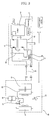
- FIG. 3 is a schematic view illustrating a configuration of a cogeneration system according to a first embodiment of the present invention.
- FIG. 4 is a partially-broken perspective view illustrating an exhaust gas heat exchanger used in the cogeneration system according to the first embodiment of the present invention.
- FIG. 5 is a cross-sectional view illustrating an inner configuration of the exhaust gas heat exchanger according to the first embodiment of the present invention.
- the cogeneration system includes an engine 50 to which fuel is supplied, a generator 51 which is driven by the engine 50 to generate electricity, a cooling water heat exchanger 52 which recovers heat from cooling water used to cool the engine 50, and an exhaust gas heat exchanger 70 which is arranged in an exhaust gas discharge conduit 53 extending from the engine 50 to recover heat from exhaust gas discharged from the engine 50.
- the cogeneration system also includes a heat transfer line 54 which transfers the recovered cooling water heat and exhaust gas heat to a cooling and heating apparatus 60.
- the electricity generated from the generator 51 is used to operate various electronic appliances including the cooling and heating apparatus 60 and illumination devices.
- the waste heat generated from the engine 50 that is, the heat generated from the cooling water used to cool the engine 50 and the heat generated from the exhaust gas discharged from the engine 50, is used in the cooling and heating apparatus 60 during a heating operation of the cooling and heating apparatus 60.
- the cogeneration system also includes a radiator 57 which includes a heat exchanger 55 and a radiating fan 56.
- the cooling and heating apparatus 60 is of a heat pump type so that it is used not only as a cooling apparatus, but also as a heating apparatus, in accordance with reversal of a refrigerant flow in a refrigerant cycle in the cooling and heating apparatus 60.
- the cooling and heating apparatus 60 includes a compressor 61, a 4-way valve 62, an outdoor heat exchanger 63, an expansion device 64, and an indoor heat exchanger 65.
- An air preheating heat exchanger 66 is arranged near the outdoor heat exchanger 63 in order to preheat air supplied toward the outdoor heat exchanger 63, using the waste heat of the engine 50 during the heating operation of the cooling and heating apparatus 60.
- the air preheating heat exchanger 66 is connected to the cooling water heat exchanger 52 and exhaust gas heat exchanger 70 via the heat transfer line 54.
- the radiator 57 is arranged in a radiating line 58 connected to the heat transfer line 54.
- reference character "P” designates pumps respectively adapted to pump a heat transfer medium such that the heat transfer medium is circulated through desired lines
- reference character "V” designates a valve adapted to change the flow path of the heat transfer medium between the heat transfer line 54 and the radiating line 58.
- the exhaust gas heat exchanger includes a shell 71, an exhaust gas path which is defined in the shell 71 to guide exhaust gas to pass through the shell 71, and a refrigerant path 72 which is defined in the shell 71 to guide a refrigerant to pass through the shell 71 such that the refrigerant heat-exchanges with the exhaust gas path.
- the shell 71 is arranged in the exhaust gas discharge conduit 53 through which the exhaust gas from the engine 50 is discharged.
- An exhaust gas inlet 73 and an exhaust gas outlet 74 are formed at opposite ends of the shell 71, respectively, such that the exhaust gas inlet 73 and exhaust gas outlet 74 communicate with the exhaust gas discharge conduit 53 to allow the exhaust gas to be introduced into the shell 71 and then to be discharged from the shell 71.
- the exhaust gas path includes a plurality of exhaust gas passages respectively defined by exhaust gas discharge tubes 80 which are arranged between the exhaust gas inlet 73 and the exhaust gas outlet 74.
- a refrigerant inlet 75 and a refrigerant outlet 76 are formed through a peripheral wall of the shell 71 to allow the refrigerant to be introduced into the shell 71 and then to be discharged from the shell 71.
- a first isolation plate 77 and a second isolation plate 78 are arranged at the exhaust gas inlet 73 and the exhaust gas outlet 74, respectively, to isolate the interior of the shell 71 from the exhaust gas inlet 73 and exhaust gas outlet 74, and thus, to define the refrigerant path in the shell 71.
- the first and second isolation plates 77 and 78 are fixed to an inner peripheral surface of the shell 71 by welding.
- a plurality of connecting holes 79 are formed through each of the first and second isolation plates 77 and 78.
- Opposite ends of each exhaust gas discharge tube 80 are connected to associated ones of the connecting holes 79 of the first and second isolation plates 77 and 78.
- a flow guide is arranged in the shell 71 to change the refrigerant path for an enhancement in heat transfer efficiency.
- the flow guide includes at least one lower flow guide 81 upwardly protruded from the bottom of the shell 71 in the interior of the shell 71, and at least one upper flow guide 82 downwardly protruded from the top of the shell 71 in the interior of the shell 71.
- the flow guide includes two lower flow guides 81 and one upper flow guide 82.
- the lower flow guides 81 are spaced apart from each other in a flow direction of the exhaust gas, and the upper flow guide 82 is arranged between the lower flow guides 81.
- a plurality of through holes are formed through each of the lower and upper flow guides 81 and 82, to allow the exhaust gas discharge tubes 80 aligned with the through holes to extend through the through holes, respectively.
- Each exhaust gas discharge tube 80 includes a bellows tube portion 83 to be thermally expandable and shrinkable, thereby preventing the exhaust gas discharge tube 80 from being damaged due to thermal deformation thereof caused by the heat of the exhaust gas.
- the bellows tube portion 83 has circular pleats arranged in a longitudinal direction of the bellows tube portion 83 to enable the bellows tube portion 83 to be easily extended and shrunken in the longitudinal direction.
- each exhaust gas discharge tube 80 is fitted in associated ones of the connecting holes 79 formed through the first and second isolation plates 77 and 78, respectively, and are fixed to the first and second isolation plates 77 and 78 around the associated connecting holes 79 by welding, respectively.
- each exhaust gas discharge tube 80 to be fitted in the associated connecting holes 79 has a circular cross-section corresponding to that of the connecting holes 79.
- each exhaust gas discharge tube 80 be made of steel use stainless (SUS).
- Electricity generated from the engine 50 during operation of the engine 50 is supplied to the cooling and heating apparatus 60, and high-temperature exhaust gas discharged from the engine 50 during the operation of the engine 50 passes through the exhaust gas heat exchanger 70 arranged in the exhaust gas discharge conduit 53.
- the exhaust gas discharged from the engine 50 is introduced into the shell 71 through the exhaust gas inlet 73 of the shell 71, and is then discharged from the shell 71 through the exhaust gas outlet 74 after passing through the exhaust gas exhaust tubes 80.
- cooling water which is a refrigerant is introduced into the shell 71 through the refrigerant inlet 75. Accordingly, heat exchange occurs in the shell 71 between the cooling water and the exhaust gas discharge tubes 80.
- the cooling water absorbs the heat of the exhaust gas transferred to the exhaust gas discharge tubes 80 through which the exhaust gas passes. As a result, the exhaust gas discharge tubes 80 are cooled by the cooling water.
- the cooling water is discharged from the shell 71 through the refrigerant outlet 76 after absorbing heat from the exhaust gas discharge tubes 80, and is supplied to the air preheating heat exchanger 66 via the heat transfer line 54.
- the cooling water preheats outdoor air introduced into the cooling and heat apparatus 60 while passing through the air preheating heat exchanger 66, using the heat absorbed from the exhaust gas discharge tubes 80, in order to achieve an enhancement in heating capability.
- each exhaust gas discharge tube 80 has an increased thermal contact area contacting the cooling water by virtue of the thermally expandable and shrinkable bellows tube portion 83 included in the exhaust gas discharge tube 80. Accordingly, an enhancement in thermal efficiency is achieved.
- first and second isolation plates 77 and 78 are fixed to the inner peripheral surface of the shell 71 by welding, it is possible to effectively prevent leakage of the cooling water.
- the flow path of the cooling water is changed to communicate with the radiating line 58 connected to the heat transfer line 54 because it is unnecessary to supply waste heat.
- the waste heat is discharged to the atmosphere through the radiator 57, or is supplied to and used in a water heater, a hot water supplier, or other systems.
- FIG. 6 is a cross-sectional view illustrating an inner configuration of an exhaust gas heat exchanger in a cogeneration system according to a second embodiment of the present invention.
- the exhaust gas heat exchanger includes a shell 90 which is provided, at opposite ends thereof, with an exhaust gas inlet 91 and an exhaust gas outlet 92, respectively, and an exhaust gas discharge tubes 93 which are arranged in the shell 90 to connect the exhaust gas inlet 91 and exhaust gas outlet 92, thereby defining an exhaust gas path.
- Each exhaust gas discharge tube 93 includes a bellows tube portion 94 to be thermally expandable and shrinkable, thereby preventing the exhaust gas discharge tube 90 from being damaged due to thermal deformation thereof caused by the heat of the exhaust gas.
- the bellows tube portion 94 has a pleat extending spirally in a longitudinal direction of the bellows tube portion 94 to enable the bellows tube portion 94 to be easily extended and shrunken in the longitudinal direction, and to achieve an enhancement in the heat transfer of the bellows tube portion 94 with cooling water.
- Other configurations of the exhaust gas heat exchanger according to the second embodiment of the present invention are identical to those of the first embodiment of the present invention, so no detailed description thereof will be given.
- FIG. 7 is a cross-sectional view illustrating an inner configuration of an exhaust gas heat exchanger in a cogeneration system according to a third embodiment of the present invention.
- the exhaust gas heat exchanger according to the third embodiment of the present invention includes a shell 100 which is provided, at opposite ends thereof, with an exhaust gas inlet 101 and an exhaust gas outlet 102, respectively, and an exhaust gas discharge tubes 103 which are arranged in the shell 100 to connect the exhaust gas inlet 101 and exhaust gas outlet 102, thereby defining an exhaust gas path.
- Each exhaust gas discharge tube 103 includes two portions, namely, a bellows tube portion 104 and a constant-diameter cylindrical tube portion 105.
- Other configurations of the exhaust gas heat exchanger according to the third embodiment of the present invention are identical to those of the first embodiment of the present invention, so no detailed description thereof will be given.
- the bellows tube portion 104 have circular pleats arranged in a longitudinal direction of the bellows tube portion 104, and be provided at a portion of the exhaust gas discharge tube 103 exposed to a higher temperature than the remaining portion of the exhaust gas discharge tube 103.
- the temperature of the exhaust gas inlet 101, into which the exhaust gas from the engine 50 is first introduced, is higher than that of the exhaust gas outlet 102. Accordingly, the bellows tube portion 104 is provided at the portion of the exhaust gas discharge tube 103 arranged at the side of the exhaust gas inlet 101, and the constant-diameter cylindrical tube portion 105 is provided at the portion of the exhaust gas discharge tube 103 arranged at the side of the exhaust gas outlet 102.
- FIG. 8 is a cross-sectional view illustrating an inner configuration of an exhaust gas heat exchanger in a cogeneration system according to a fourth embodiment of the present invention.
- the exhaust gas heat exchanger according to the fourth embodiment of the present invention includes a shell 110 which is provided, at opposite ends thereof, with an exhaust gas inlet 111 and an exhaust gas outlet 112, respectively, and an exhaust gas discharge tubes 113 which are arranged in the shell 110 to connect the exhaust gas inlet 111 and exhaust gas outlet 112, thereby defining an exhaust gas path.
- Each exhaust gas discharge tube 113 includes two portions, namely, a bellows tube portion 114 and a constant-diameter cylindrical tube portion 115.
- the bellows tube portion 114 has a pleat extending spirally in a longitudinal direction of the bellows tube portion 114.
- Other configurations of the exhaust gas heat exchanger according to the fourth embodiment of the present invention are identical to those of the third embodiment of the present invention, so no detailed description thereof will be given.
- FIG. 9 is a cross-sectional view illustrating an inner configuration of an exhaust gas heat exchanger in a cogeneration system according to a fifth embodiment of the present invention.
- the exhaust gas heat exchanger according to the fifth embodiment of the present invention has the same configuration as that of the first embodiment of the present invention, except that the exhaust gas heat exchanger includes a plurality of exhaust gas discharge tubes 120 each having a bellows tube portion which is formed at at least a portion of the exhaust gas discharge tube 120, and is provided with straight pleats extending in a longitudinal direction of the exhaust gas discharge tube 120 while being arranged in a circumferential direction of the exhaust gas discharge tube 120. Accordingly, no further detailed description will be given of the exhaust gas heat exchanger according to the fifth embodiment of the present invention.
- the above-described exhaust gas heat exchanger in the cogeneration system according to the present invention provides various effects.
- each exhaust gas discharge tube in the exhaust gas heat exchanger according to the present invention has a bellows tube structure such that the exhaust gas discharge tube is thermally expandable and shrinkable, it is possible to prevent the exhaust gas discharge tube from being damaged due to repeated thermal expansion and shrinkage thereof caused by hot exhaust gas passing through the exhaust gas discharge tube. Accordingly, an enhancement in durability is achieved.
- each exhaust gas discharge tube includes a bellows tube portion, the contact are of the exhaust gas discharge tube contacting cooling water is increased, thereby achieving an enhancement in heat transfer efficiency.
- each exhaust gas discharge tube is thermally expandable and retractable, the first and second isolation plates can be fixed to the inner peripheral surface of the shell by welding. Accordingly, it is possible to effectively prevent leakage of cooling water.
Landscapes
- Engineering & Computer Science (AREA)
- Chemical & Material Sciences (AREA)
- Mechanical Engineering (AREA)
- General Engineering & Computer Science (AREA)
- Physics & Mathematics (AREA)
- Chemical Kinetics & Catalysis (AREA)
- Thermal Sciences (AREA)
- Combustion & Propulsion (AREA)
- Health & Medical Sciences (AREA)
- Toxicology (AREA)
- Geometry (AREA)
- Heat-Exchange Devices With Radiators And Conduit Assemblies (AREA)
- Exhaust Silencers (AREA)
- Details Of Heat-Exchange And Heat-Transfer (AREA)
Applications Claiming Priority (1)
| Application Number | Priority Date | Filing Date | Title |
|---|---|---|---|
| KR1020040104370A KR100649597B1 (ko) | 2004-12-10 | 2004-12-10 | 열병합 시스템의 배기가스 열교환기 |
Publications (1)
| Publication Number | Publication Date |
|---|---|
| EP1669568A1 true EP1669568A1 (fr) | 2006-06-14 |
Family
ID=35929603
Family Applications (1)
| Application Number | Title | Priority Date | Filing Date |
|---|---|---|---|
| EP05026968A Withdrawn EP1669568A1 (fr) | 2004-12-10 | 2005-12-09 | Echangeur de chaleur de gaz d'échappement pour un système de cogénération |
Country Status (5)
| Country | Link |
|---|---|
| US (1) | US20060144585A1 (fr) |
| EP (1) | EP1669568A1 (fr) |
| JP (1) | JP2006170607A (fr) |
| KR (1) | KR100649597B1 (fr) |
| CN (1) | CN1786641A (fr) |
Cited By (5)
| Publication number | Priority date | Publication date | Assignee | Title |
|---|---|---|---|---|
| EP2075522A1 (fr) * | 2007-12-28 | 2009-07-01 | VALEO AUTOSYSTEMY Sp. Z. o.o. | Faisceau d'échange de chaleur pour échangeur de chaleur |
| WO2012007359A1 (fr) * | 2010-07-13 | 2012-01-19 | Behr Gmbh & Co. Kg | Système d'utilisation de la chaleur dissipée d'un moteur à combustion interne |
| DE102011081031A1 (de) * | 2011-08-16 | 2013-02-21 | Behr Gmbh & Co. Kg | Abgaswärmeübertrager |
| BE1020321A3 (nl) * | 2011-10-19 | 2013-08-06 | Atlas Copco Airpower Nv | Buizenwarmtewisselaar en compressoreenheid daarmee uitgerust. |
| EP3106821A1 (fr) * | 2015-06-18 | 2016-12-21 | Borgwarner Emissions Systems Spain, S.L.U. | Échangeur de chaleur |
Families Citing this family (28)
| Publication number | Priority date | Publication date | Assignee | Title |
|---|---|---|---|---|
| KR20060112844A (ko) * | 2005-04-28 | 2006-11-02 | 엘지전자 주식회사 | 열병합 발전 시스템 |
| KR100638223B1 (ko) * | 2005-06-16 | 2006-10-27 | 엘지전자 주식회사 | 열병합 발전 시스템 |
| DE102008034819A1 (de) * | 2008-07-23 | 2010-01-28 | Smk Systeme Metall Kunststoff Gmbh & Co. Kg. | Abgaskühler |
| CN101782340B (zh) * | 2009-01-15 | 2013-06-12 | 王智慧 | 多级式高效波纹管余热回收装置 |
| JP5286104B2 (ja) * | 2009-02-19 | 2013-09-11 | パーパス株式会社 | 排熱回収方法、排熱回収装置及びコジェネレーションシステム |
| CN101586920B (zh) * | 2009-06-22 | 2011-05-11 | 中山华帝燃具股份有限公司 | 一种管壳式换热器 |
| TWI385354B (zh) * | 2009-11-27 | 2013-02-11 | Univ Chienkuo Technology | Automotive exhaust gas generator |
| US20110290460A1 (en) * | 2010-05-28 | 2011-12-01 | Chevron U.S.A. Inc. | Multipass tubular heat exchanger and associated pass partition plate, channel cover, and methods |
| ITCO20110033A1 (it) | 2011-08-25 | 2013-02-26 | Nuovo Pignone Spa | Scambiatore di calore integrato con compensazione della pressione e metodo |
| JP2013083371A (ja) * | 2011-10-06 | 2013-05-09 | Hitachi Industrial Equipment Systems Co Ltd | スクリュー圧縮機 |
| CN102720578A (zh) * | 2012-06-27 | 2012-10-10 | 浙江大学 | 防爆柴油机排气管 |
| KR101367320B1 (ko) | 2012-08-22 | 2014-03-12 | 현대자동차주식회사 | 배기열 회수용 배기파이프의 구조 |
| WO2014175854A1 (fr) * | 2013-04-22 | 2014-10-30 | International Engine Intellectual Property Company, Llc | Stockage de réducteur |
| DE102013011477A1 (de) * | 2013-07-09 | 2015-01-15 | Volkswagen Aktiengesellschaft | Antriebseinheit für ein Kraftfahrzeug |
| JP6041767B2 (ja) * | 2013-08-07 | 2016-12-14 | 本田技研工業株式会社 | エンジン駆動作業機 |
| CN104329146B (zh) * | 2013-11-01 | 2017-07-11 | 浙江格瑶电子科技有限公司 | 一种具有船舶柴油机排气管余热回收转换器 |
| CN103759556A (zh) * | 2014-01-20 | 2014-04-30 | 扬州澄露环境工程有限公司 | 急冷及空气预热组合装置 |
| US10302047B2 (en) * | 2016-03-22 | 2019-05-28 | Ge Global Sourcing Llc | Method and systems for an EGR cooler including cooling tubes with a compliant region |
| CN106014578A (zh) * | 2016-08-09 | 2016-10-12 | 江苏中欣联科动力有限公司 | 柴油机降噪系统 |
| US20180194196A1 (en) * | 2017-01-06 | 2018-07-12 | GM Global Technology Operations LLC | Systems and methods utilizing heat pumps to recover thermal energy from exhaust gas |
| CN106870076B (zh) * | 2017-03-02 | 2019-04-09 | 湖北工业大学 | 热交换器以及热电转换装置 |
| US10697407B2 (en) | 2017-04-06 | 2020-06-30 | Transportation Ip Holdings, Llc | Method and systems for a multistage exhaust gas cooler |
| KR101779936B1 (ko) * | 2017-05-11 | 2017-09-20 | (주)귀뚜라미 | 배기가스를 이용하는 열 교환 장치 |
| US11041637B2 (en) * | 2017-06-27 | 2021-06-22 | Imby Energy, Inc. | Cogeneration systems and methods for generating heating and electricity |
| KR20200124582A (ko) * | 2019-04-24 | 2020-11-03 | 현대자동차주식회사 | 배기가스 재순환용 쿨러 |
| CN111472872B (zh) * | 2020-05-29 | 2024-05-28 | 郑州佛光发电设备股份有限公司 | 一种热交换管冷却式发动机排气装置 |
| US11885286B2 (en) * | 2021-04-09 | 2024-01-30 | Caterpillar Inc. | Separator plate for cooling tubes |
| CN114719635B (zh) * | 2022-04-28 | 2023-11-03 | 广西玉柴动力股份有限公司 | 一种高速艇发动机排气管的换热方法及装置 |
Citations (5)
| Publication number | Priority date | Publication date | Assignee | Title |
|---|---|---|---|---|
| US4203312A (en) * | 1977-09-29 | 1980-05-20 | Spiral Tubing Corporation | Corrugated tubing with variable depth corrugations and method of making the same |
| US4685292A (en) * | 1985-09-09 | 1987-08-11 | Zwick Energy Research Organization, Inc. | Exhaust cooling system for internal combustion engine |
| JPH09229579A (ja) * | 1996-02-23 | 1997-09-05 | Usui Internatl Ind Co Ltd | 伝熱管およびこれを使用した多管式熱交換器 |
| DE29708011U1 (de) * | 1997-05-03 | 1998-08-27 | Solvay Verwaltungs- und Vermittlungs GmbH, 30173 Hannover | Abgasrückkühler |
| JP2001342909A (ja) * | 2000-06-05 | 2001-12-14 | Hino Motors Ltd | Egrクーラ |
Family Cites Families (4)
| Publication number | Priority date | Publication date | Assignee | Title |
|---|---|---|---|---|
| US2081043A (en) * | 1933-03-13 | 1937-05-18 | Air Liquide | Heat exchanger |
| JPS5339361A (en) * | 1976-09-22 | 1978-04-11 | Kobe Steel Ltd | Method of extruding and working amorphous high molecule |
| JPS5987580A (ja) * | 1982-11-12 | 1984-05-21 | Casio Comput Co Ltd | 筆記文字認識装置 |
| JPH1183352A (ja) * | 1997-09-05 | 1999-03-26 | Sanou Kogyo Kk | 熱交換器 |
-
2004
- 2004-12-10 KR KR1020040104370A patent/KR100649597B1/ko not_active Expired - Fee Related
-
2005
- 2005-12-09 JP JP2005356528A patent/JP2006170607A/ja active Pending
- 2005-12-09 EP EP05026968A patent/EP1669568A1/fr not_active Withdrawn
- 2005-12-12 US US11/298,532 patent/US20060144585A1/en not_active Abandoned
- 2005-12-12 CN CNA2005101314280A patent/CN1786641A/zh active Pending
Patent Citations (5)
| Publication number | Priority date | Publication date | Assignee | Title |
|---|---|---|---|---|
| US4203312A (en) * | 1977-09-29 | 1980-05-20 | Spiral Tubing Corporation | Corrugated tubing with variable depth corrugations and method of making the same |
| US4685292A (en) * | 1985-09-09 | 1987-08-11 | Zwick Energy Research Organization, Inc. | Exhaust cooling system for internal combustion engine |
| JPH09229579A (ja) * | 1996-02-23 | 1997-09-05 | Usui Internatl Ind Co Ltd | 伝熱管およびこれを使用した多管式熱交換器 |
| DE29708011U1 (de) * | 1997-05-03 | 1998-08-27 | Solvay Verwaltungs- und Vermittlungs GmbH, 30173 Hannover | Abgasrückkühler |
| JP2001342909A (ja) * | 2000-06-05 | 2001-12-14 | Hino Motors Ltd | Egrクーラ |
Non-Patent Citations (2)
| Title |
|---|
| PATENT ABSTRACTS OF JAPAN vol. 1998, no. 01 30 January 1998 (1998-01-30) * |
| PATENT ABSTRACTS OF JAPAN vol. 2002, no. 04 4 August 2002 (2002-08-04) * |
Cited By (6)
| Publication number | Priority date | Publication date | Assignee | Title |
|---|---|---|---|---|
| EP2075522A1 (fr) * | 2007-12-28 | 2009-07-01 | VALEO AUTOSYSTEMY Sp. Z. o.o. | Faisceau d'échange de chaleur pour échangeur de chaleur |
| WO2012007359A1 (fr) * | 2010-07-13 | 2012-01-19 | Behr Gmbh & Co. Kg | Système d'utilisation de la chaleur dissipée d'un moteur à combustion interne |
| US9051852B2 (en) | 2010-07-13 | 2015-06-09 | Behr Gmbh & Co. Kg | System for utilizing waste heat of an internal combustion engine |
| DE102011081031A1 (de) * | 2011-08-16 | 2013-02-21 | Behr Gmbh & Co. Kg | Abgaswärmeübertrager |
| BE1020321A3 (nl) * | 2011-10-19 | 2013-08-06 | Atlas Copco Airpower Nv | Buizenwarmtewisselaar en compressoreenheid daarmee uitgerust. |
| EP3106821A1 (fr) * | 2015-06-18 | 2016-12-21 | Borgwarner Emissions Systems Spain, S.L.U. | Échangeur de chaleur |
Also Published As
| Publication number | Publication date |
|---|---|
| CN1786641A (zh) | 2006-06-14 |
| US20060144585A1 (en) | 2006-07-06 |
| JP2006170607A (ja) | 2006-06-29 |
| KR20060065883A (ko) | 2006-06-14 |
| KR100649597B1 (ko) | 2006-11-28 |
Similar Documents
| Publication | Publication Date | Title |
|---|---|---|
| US20060144585A1 (en) | Exhaust gas heat exchanger for cogeneration system | |
| JP4033402B2 (ja) | 熱交換器 | |
| JP5358329B2 (ja) | コージェネレーション装置 | |
| EP0737804B1 (fr) | Dispositif de préchauffage du carburant d'une turbine à gaz | |
| KR100657471B1 (ko) | 코제너레이션 시스템 | |
| KR20060016390A (ko) | 코제너레이션 시스템 | |
| EP1628100A2 (fr) | Système de cogénération d'énergie et échangeur de chaleur du gaz d'échappement de celui-ci | |
| EP1628091A2 (fr) | Conditionneur d'air combiné avec un système de génération d'électricité | |
| US7481071B2 (en) | Cooling/heating apparatus using cogeneration system | |
| US7240504B2 (en) | Cogeneration system | |
| US7543631B2 (en) | Exhaust gas heat exchanger for cogeneration system | |
| JP2006002622A (ja) | ガスタービン用再生器 | |
| CN110792506A (zh) | 一种用于内燃机的水冷空冷一体式冷却器 | |
| KR101779936B1 (ko) | 배기가스를 이용하는 열 교환 장치 | |
| JPH0642406A (ja) | 熱併給発電装置およびその排熱回収器 | |
| KR20110022044A (ko) | 개선된 열교환기 튜브 및 공기-대-공기 인터쿨러 | |
| JP2004060975A (ja) | 熱交換用ダクト | |
| KR100624788B1 (ko) | 열병합 시스템의 열교환 소음기 | |
| KR0133034Y1 (ko) | 공기조화기의 냉매팽창장치 | |
| KR20190035061A (ko) | 공기 조화기 | |
| JPH0141884Y2 (fr) | ||
| KR100673436B1 (ko) | 열병합시스템의 소음기 | |
| JP2008300157A (ja) | 燃料電池ユニット | |
| CN117722808A (zh) | 一种间接空冷系统及预暖除露方法 |
Legal Events
| Date | Code | Title | Description |
|---|---|---|---|
| PUAI | Public reference made under article 153(3) epc to a published international application that has entered the european phase |
Free format text: ORIGINAL CODE: 0009012 |
|
| 17P | Request for examination filed |
Effective date: 20060105 |
|
| AK | Designated contracting states |
Kind code of ref document: A1 Designated state(s): AT BE BG CH CY CZ DE DK EE ES FI FR GB GR HU IE IS IT LI LT LU LV MC NL PL PT RO SE SI SK TR |
|
| AX | Request for extension of the european patent |
Extension state: AL BA HR MK YU |
|
| 17Q | First examination report despatched |
Effective date: 20070112 |
|
| AKX | Designation fees paid |
Designated state(s): DE FR GB |
|
| STAA | Information on the status of an ep patent application or granted ep patent |
Free format text: STATUS: THE APPLICATION IS DEEMED TO BE WITHDRAWN |
|
| 18D | Application deemed to be withdrawn |
Effective date: 20080118 |