EP1669574B1 - Dispositif et système de commande de la régénération d'un filtre à particules - Google Patents
Dispositif et système de commande de la régénération d'un filtre à particules Download PDFInfo
- Publication number
- EP1669574B1 EP1669574B1 EP05109009A EP05109009A EP1669574B1 EP 1669574 B1 EP1669574 B1 EP 1669574B1 EP 05109009 A EP05109009 A EP 05109009A EP 05109009 A EP05109009 A EP 05109009A EP 1669574 B1 EP1669574 B1 EP 1669574B1
- Authority
- EP
- European Patent Office
- Prior art keywords
- particulate filter
- temperature
- regeneration
- modeling
- combustion
- Prior art date
- Legal status (The legal status is an assumption and is not a legal conclusion. Google has not performed a legal analysis and makes no representation as to the accuracy of the status listed.)
- Expired - Lifetime
Links
Images

Classifications
-
- F—MECHANICAL ENGINEERING; LIGHTING; HEATING; WEAPONS; BLASTING
- F01—MACHINES OR ENGINES IN GENERAL; ENGINE PLANTS IN GENERAL; STEAM ENGINES
- F01N—GAS-FLOW SILENCERS OR EXHAUST APPARATUS FOR MACHINES OR ENGINES IN GENERAL; GAS-FLOW SILENCERS OR EXHAUST APPARATUS FOR INTERNAL-COMBUSTION ENGINES
- F01N9/00—Electrical control of exhaust gas treating apparatus
- F01N9/005—Electrical control of exhaust gas treating apparatus using models instead of sensors to determine operating characteristics of exhaust systems, e.g. calculating catalyst temperature instead of measuring it directly
-
- F—MECHANICAL ENGINEERING; LIGHTING; HEATING; WEAPONS; BLASTING
- F01—MACHINES OR ENGINES IN GENERAL; ENGINE PLANTS IN GENERAL; STEAM ENGINES
- F01N—GAS-FLOW SILENCERS OR EXHAUST APPARATUS FOR MACHINES OR ENGINES IN GENERAL; GAS-FLOW SILENCERS OR EXHAUST APPARATUS FOR INTERNAL-COMBUSTION ENGINES
- F01N9/00—Electrical control of exhaust gas treating apparatus
- F01N9/002—Electrical control of exhaust gas treating apparatus of filter regeneration
-
- F—MECHANICAL ENGINEERING; LIGHTING; HEATING; WEAPONS; BLASTING
- F02—COMBUSTION ENGINES; HOT-GAS OR COMBUSTION-PRODUCT ENGINE PLANTS
- F02D—CONTROLLING COMBUSTION ENGINES
- F02D41/00—Electrical control of supply of combustible mixture or its constituents
- F02D41/02—Circuit arrangements for generating control signals
- F02D41/021—Introducing corrections for particular conditions exterior to the engine
- F02D41/0235—Introducing corrections for particular conditions exterior to the engine in relation with the state of the exhaust gas treating apparatus
- F02D41/027—Introducing corrections for particular conditions exterior to the engine in relation with the state of the exhaust gas treating apparatus to purge or regenerate the exhaust gas treating apparatus
- F02D41/029—Introducing corrections for particular conditions exterior to the engine in relation with the state of the exhaust gas treating apparatus to purge or regenerate the exhaust gas treating apparatus the exhaust gas treating apparatus being a particulate filter
-
- F—MECHANICAL ENGINEERING; LIGHTING; HEATING; WEAPONS; BLASTING
- F02—COMBUSTION ENGINES; HOT-GAS OR COMBUSTION-PRODUCT ENGINE PLANTS
- F02D—CONTROLLING COMBUSTION ENGINES
- F02D41/00—Electrical control of supply of combustible mixture or its constituents
- F02D41/02—Circuit arrangements for generating control signals
- F02D41/14—Introducing closed-loop corrections
- F02D41/1401—Introducing closed-loop corrections characterised by the control or regulation method
- F02D2041/1433—Introducing closed-loop corrections characterised by the control or regulation method using a model or simulation of the system
-
- F—MECHANICAL ENGINEERING; LIGHTING; HEATING; WEAPONS; BLASTING
- F02—COMBUSTION ENGINES; HOT-GAS OR COMBUSTION-PRODUCT ENGINE PLANTS
- F02D—CONTROLLING COMBUSTION ENGINES
- F02D2200/00—Input parameters for engine control
- F02D2200/02—Input parameters for engine control the parameters being related to the engine
- F02D2200/08—Exhaust gas treatment apparatus parameters
- F02D2200/0802—Temperature of the exhaust gas treatment apparatus
- F02D2200/0804—Estimation of the temperature of the exhaust gas treatment apparatus
-
- F—MECHANICAL ENGINEERING; LIGHTING; HEATING; WEAPONS; BLASTING
- F02—COMBUSTION ENGINES; HOT-GAS OR COMBUSTION-PRODUCT ENGINE PLANTS
- F02D—CONTROLLING COMBUSTION ENGINES
- F02D2200/00—Input parameters for engine control
- F02D2200/02—Input parameters for engine control the parameters being related to the engine
- F02D2200/08—Exhaust gas treatment apparatus parameters
- F02D2200/0812—Particle filter loading
-
- F—MECHANICAL ENGINEERING; LIGHTING; HEATING; WEAPONS; BLASTING
- F02—COMBUSTION ENGINES; HOT-GAS OR COMBUSTION-PRODUCT ENGINE PLANTS
- F02D—CONTROLLING COMBUSTION ENGINES
- F02D2200/00—Input parameters for engine control
- F02D2200/70—Input parameters for engine control said parameters being related to the vehicle exterior
- F02D2200/701—Information about vehicle position, e.g. from navigation system or GPS signal
-
- Y—GENERAL TAGGING OF NEW TECHNOLOGICAL DEVELOPMENTS; GENERAL TAGGING OF CROSS-SECTIONAL TECHNOLOGIES SPANNING OVER SEVERAL SECTIONS OF THE IPC; TECHNICAL SUBJECTS COVERED BY FORMER USPC CROSS-REFERENCE ART COLLECTIONS [XRACs] AND DIGESTS
- Y02—TECHNOLOGIES OR APPLICATIONS FOR MITIGATION OR ADAPTATION AGAINST CLIMATE CHANGE
- Y02T—CLIMATE CHANGE MITIGATION TECHNOLOGIES RELATED TO TRANSPORTATION
- Y02T10/00—Road transport of goods or passengers
- Y02T10/10—Internal combustion engine [ICE] based vehicles
- Y02T10/40—Engine management systems
Definitions
- the invention relates to a method and a control system for controlling the regeneration of the particulate filter of an internal combustion engine, wherein the regeneration is carried out by the combustion of accumulated particles.
- Particulate filters are used in motor vehicles to remove harmful (soot) particles from the exhaust gases of an internal combustion engine, in particular a diesel engine.
- the particulate filters have to be cleaned from time to time by the accumulated particles, this regeneration is done by burning the particles in the filter.
- the conditions for such combustion can be adjusted by the oxygen concentration in the exhaust gas and the exhaust gas temperature. However, if the temperatures become too high during regeneration in the filter, it may cause damage.
- the object of the invention is to safely and efficiently prevent damage to the particulate filter due to excessive temperatures during regeneration.
- the inventive method is used to control the regeneration of the particulate filter of an internal combustion engine, in particular a diesel engine, wherein the regeneration is carried out by combustion of particles accumulated in the filter.
- the method is characterized in that it comprises a spatially resolved modeling of the combustion process in the particulate filter.
- the combustion process can be spatially one-dimensional along the flow direction of the Exhaust gases in the particulate filter (ie along the axis of the particulate filter) are modeled.
- Such an axially oriented simulation can optionally also be carried out for two or more parallel channels of the particle filter (eg a channel in the middle and one at the edge), so as to obtain a quasi two-dimensional image.
- a complete two-dimensional or even three-dimensional simulation of the combustion process is possible with a corresponding computational effort.
- the temperature, the temperature gradient, the amount of particles and / or the combustion rate within the particle filter are preferably modeled in a spatially resolved manner.
- the temperature and the temperature gradient are the quantities which are of particular relevance for protection of the particle filter.
- the modeling must be provided with certain input variables as boundary conditions. These input variables are preferably the oxygen concentration, the temperature and / or the mass flow of the exhaust gases entering the particle filter.
- the variables mentioned can be based in particular on current measured values in order to reflect the conditions in the internal combustion engine as realistically as possible.
- the information available from the modeling can be used for a variety of purposes. Preferably, they are used to control the internal combustion engine so that a target value for the local combustion rate is maintained within the particulate filter.
- This target specification may in particular consist of a minimum and maximum local combustion rate, which should not be undershot or exceeded.
- the internal combustion engine can be controlled such that upper threshold values for the temperature and / or the temperature gradient within the particulate filter are not exceeded in order to prevent damage to the filter.
- lower threshold values for the temperature and / or the temperature gradient within the particulate filter may also be specified, which should not be undershot in order to run the regeneration process at high speed and therefore high fuel economy.
- the influencing of the combustion processes within the particulate filter can be effected, in particular, by controlling the oxygen concentration, the temperature and / or the mass flow of the exhaust gas entering the particulate filters as a function of the modeling.
- the oxygen concentration is of particular importance, since this determines the combustion rate within the filter.
- the variables mentioned can be modulated by specification of a multiplicity of different operating parameters of the internal combustion engine.
- the effects of predicted ways of driving are also modeled. For example, it can be displayed via a navigation system that an uphill or motorway journey is imminent, in which the internal combustion engine is expected to be operated at high load.
- the effects of the resulting increased exhaust gas temperatures can be predicted in this case with the modeling.
- the invention further relates to a control system for controlling the regeneration of the particulate filter of an internal combustion engine by combustion of accumulated particles, wherein the control system includes a model unit for spatially resolved modeling of the combustion process in the particulate filter.
- the control system with the model unit can be realized in particular in the form of a microcomputer with corresponding hardware and software, in which case the model unit contains a discretized, digitized model of the combustion processes.
- the control system is also preferably designed to carry out a method of the type described above.
- To the control system may optionally include an oxygen probe, which is arranged in the exhaust path of the internal combustion engine in front of the particle filter. With such a probe, the oxygen concentration in the exhaust gas can then be measured, which is an important input for the model unit.
- oxygen probes are often already present in a motor vehicle as so-called lambda probes for controlling the exhaust aftertreatment devices.
- FIG. 1 an internal combustion engine 1 is shown, in the exhaust path 2, a diesel particulate filter 4 is arranged.
- the accumulated in the particulate filter 4 from the exhaust gas of the internal combustion engine 1 soot particles must be removed from time to time by a regeneration of the filter 4.
- the temperature of the exhaust gas is increased so much that the oxidation of the soot stored in the filter 4 is possible.
- the regeneration can lead to very high temperatures or temperature gradients in the particulate filter 4, which can then damage the substrate and - in the case of a catalytic particulate filter - also the catalytic coating of the filter.
- control system 10 which can be implemented for example in the form of a microprocessor with appropriate software.
- the control system 10 includes a model unit 11, in which the combustion processes within the particulate filter 4 are spatially resolved and simulated in a time- and location-discrete manner.
- model unit 11 in which the combustion processes within the particulate filter 4 are spatially resolved and simulated in a time- and location-discrete manner.
- single cells 12-1, 12-2, ... 12-n of the model unit 11 represent successive discrete compartments along the extension of the particulate filter 4th
- the first cell 12-1 at the upstream end of the (virtual) particulate filter receives as input the temperature Tg in , the mass flow v in , and the oxygen concentration C O2 of the exhaust gas entering the particulate filter.
- the individual cells each have the combustion rate or rate of change of the particle loading, dw i / dt, and the temperature Tw of the channel walls or their change as a state variable.
- Tg 1x the inlet channel temperature
- Tg 2x the outlet channel temperature
- v 1x the gas velocity in the inlet channel
- v 2x the gas velocity in the outlet channel.
- the dynamics of these quantities is modeled by the expert familiar relations.
- the rate of change dw / dt of the particle loading is from the oxygen concentration in the exhaust gas and the temperature of the particle loading dependent.
- the oxidation of soot particles in turn leads to the production of heat and thus to an increase in temperature of the exhaust gas and the particle load.
- the individual particle combustion rates dw i / dt determined in the cells are fed to a block 13 in which the maximum of these values is determined.
- the maximum combustion rate thus determined within the particulate filter, max (dw / dt) is in turn supplied to a control unit 14, which exerts a controlling influence on the internal combustion engine 1.
- the control unit 14 has information about the particle load, combustion rate and temperature along the filter axis, which allow safe and fast regeneration.
- the temperature can be kept close to allowable values without maintaining an excessively large safety distance, thereby achieving a high combustion rate and thus low fuel consumption for regeneration.
- the particle combustion rate in the particulate filter 4 can be influenced in particular by the concentrations of oxygen and NOx, the temperature and the mass flow of the exhaust gas which enters the particulate filter 4.
- the variables mentioned can in turn be controlled by the control unit 14 via various operating parameters of the internal combustion engine 1, for example via a subsequent injection of fuel into the cylinder or into the exhaust manifold, via an inlet throttle, via an exhaust gas recirculation valve (or an EGR throttle) via a Bypass device, via the VGT position and the like.
- these variables can not be controlled independently of one another, ie a change in the oxygen concentration in the exhaust gas can not be achieved, for example, without influencing the mass flow and / or the temperature.
- the combustion of the soot is more sensitive to the oxygen concentration than to the mass flow of the exhaust gas, since the former directly affects the combustion reactions, while the mass flow through a cooling effect affects the temperature increase in the filter.
- the oxygen concentration can be monitored by the control unit 14 preferably via a lambda probe 3 in the exhaust path 2 in front of the particle filter 4 in a feedback loop. Since the dynamic response of the filter to changes in temperature is slower, the temperature control is generally slower than the control over the oxygen concentration.
- the control system 10 may also be used to supplement existing regeneration strategies, preventing excessive local heat release under critical conditions and thus filter failure.
- the control system 10 monitors the progress of the regeneration process and takes the above-described actions as the maximum particulate combustion rate within the filter approaches a predetermined upper threshold to maintain the burn rate within safe limits. Since the model 11 and the controller 14 are constantly working, not only active regenerations, but also unintentional, potentially damaging regeneration processes are controlled and kept within safe limits.
- the model 11 can also predict the future system behavior for an assumed future driving pattern. With this information, more sophisticated control measures can then be taken so that the regulator can for example anticipate and respond to high reaction rates in advance.
- the particle filter 4 can be coated both uncoated and catalytically. With uncoated filters, the control system helps to prevent melting or cracking due to high temperatures and temperature gradients, while in coated filters the system additionally prevents thermal deactivation of the catalyst, which typically occurs at much lower temperatures than those hazardous to the substrate.
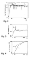
- FIG. 2 For a (simulated) city trip, the curves of the conventional (uncontrolled) combustion rate U and the combustion rate C controlled by the above-mentioned method are plotted over the time t (horizontal axis).
- the line S indicates the threshold value at which the method according to the invention (curve C) has taken measures against a further increase in the combustion rate. The regulatory procedure keeps the combustion rate within safe limits.
- FIG. 4 shows that the total particle conversion in the process according to the invention (curve C) is initially slower than in the uncontrolled case (curve U), but that this difference is made up for later and the regenerations are completed at about the same time.
- a lower threshold could be set, below which measures are taken to increase the rate of combustion. In this way, a maximum combustion rate could be achieved in the particulate filter in compliance with safety limits, which in turn benefits the fuel consumption.
Landscapes
- Engineering & Computer Science (AREA)
- Chemical & Material Sciences (AREA)
- Combustion & Propulsion (AREA)
- Mechanical Engineering (AREA)
- General Engineering & Computer Science (AREA)
- Analytical Chemistry (AREA)
- Chemical Kinetics & Catalysis (AREA)
- Processes For Solid Components From Exhaust (AREA)
- Filtering Of Dispersed Particles In Gases (AREA)
- Exhaust Gas After Treatment (AREA)
Claims (9)
- Procédé de contrôle de la régénération du filtre à particules (4) d'un moteur à combustion interne (1) par combustion des particules recueillies,
caractérisé en ce que
le processus de combustion est modélisé à résolution spatiale et les informations fournies par la modélisation sont utilisées pour commander le moteur à combustion interne (1) de manière à respecter une prescription de consigne du taux local de combustion à l'intérieur du filtre à particules (4). - Procédé selon la revendication 1, caractérisé en ce que le processus de combustion est modélisé en une dimension le long d'au moins un canal du filtre à particules (4).
- Procédé selon les revendications 1 ou 2, caractérisé en ce que la température, le gradient de température, la quantité de particules et/ou le taux de combustion à l'intérieur du filtre à particules (4) sont modélisés.
- Procédé selon au moins l'une des revendications 1 à 3, caractérisé en ce que la modélisation utilise comme grandeurs d'entrée la concentration en oxygène, la température et/ou le débit massique des gaz d'échappement qui pénètrent dans le filtre à particules (4).
- Procédé selon au moins l'une des revendications 1 à 4, caractérisé en ce que le moteur à combustion interne (1) est commandé de manière à ne pas dépasser vers le haut et/ou vers le bas des valeurs de seuil (S) de la température et/ou du gradient de température à l'intérieur du filtre à particules (4).
- Procédé selon au moins l'une des revendications 1 à 5, caractérisé en ce que la concentration en oxygène et/ou le débit massique des gaz d'échappement qui pénètrent dans le filtre à particules (4) sont contrôlés en fonction de la modélisation du processus de combustion.
- Procédé selon au moins l'une des revendications 1 à 6, caractérisé en ce que les effets de mode de conduite prédits sont modélisés.
- Système de régulation (10) destiné à contrôler la régénération du filtre à particules (4) d'un moteur à combustion interne (1) par combustion des particules recueillies,
caractérisé par
une unité de modélisation (11) qui modélise à résolution spatiale le processus de combustion dans le filtre à particules (4) et une unité de régulation (14) qui commande le moteur à combustion interne (1) en utilisant les informations fournies par la modélisation de manière à respecter une prescription de consigne du taux local de combustion à l'intérieur du filtre à particules (4). - Système de régulation selon la revendication 8, caractérisé en ce qu'il est configuré en vue de mettre en oeuvre un procédé selon au moins l'une des revendications 2 à 8.
Applications Claiming Priority (1)
| Application Number | Priority Date | Filing Date | Title |
|---|---|---|---|
| DE102004000065A DE102004000065A1 (de) | 2004-12-07 | 2004-12-07 | Verfahren und Vorrichtung zur Kontrolle der Regeneration eines Partikelfilters |
Publications (3)
| Publication Number | Publication Date |
|---|---|
| EP1669574A2 EP1669574A2 (fr) | 2006-06-14 |
| EP1669574A3 EP1669574A3 (fr) | 2008-11-26 |
| EP1669574B1 true EP1669574B1 (fr) | 2012-04-04 |
Family
ID=35735048
Family Applications (1)
| Application Number | Title | Priority Date | Filing Date |
|---|---|---|---|
| EP05109009A Expired - Lifetime EP1669574B1 (fr) | 2004-12-07 | 2005-09-29 | Dispositif et système de commande de la régénération d'un filtre à particules |
Country Status (2)
| Country | Link |
|---|---|
| EP (1) | EP1669574B1 (fr) |
| DE (1) | DE102004000065A1 (fr) |
Families Citing this family (12)
| Publication number | Priority date | Publication date | Assignee | Title |
|---|---|---|---|---|
| US7958723B2 (en) | 2007-05-15 | 2011-06-14 | GM Global Technology Operations LLC | Electrically heated particulate filter propagation support methods and systems |
| US8011180B2 (en) * | 2007-08-16 | 2011-09-06 | Ford Global Technologies, Llc | Particulate filter regeneration |
| US9284870B2 (en) | 2007-09-14 | 2016-03-15 | GM Global Technology Operations LLC | Electrically heated particulate matter filter soot control system |
| SE536026C2 (sv) * | 2010-08-31 | 2013-04-09 | Scania Cv Ab | Förfarande och system för avgasrening |
| US8601798B2 (en) * | 2011-03-11 | 2013-12-10 | GM Global Technology Operations LLC | Particulate filter regeneration process diagnostic |
| DE102012022712A1 (de) * | 2012-11-21 | 2014-05-22 | Deutz Aktiengesellschaft | Dieselpartikelfilter und Verfahren zur Regeneration desselben |
| BR112017025377A2 (pt) | 2015-06-11 | 2018-08-07 | Scania Cv Ab | método e sistema para controlar um sistema de conversor catalítico |
| DE102016114427A1 (de) | 2016-08-04 | 2018-02-08 | Volkswagen Aktiengesellschaft | Verfahren zur Regeneration eines Partikelfilters |
| WO2020044315A1 (fr) | 2018-08-30 | 2020-03-05 | University Of Kansas | Modèle de prédiction avancée de l'oxydation liée à la suie |
| US11879369B2 (en) * | 2020-04-08 | 2024-01-23 | Nissan Motor Co., Ltd. | Vehicle control method and vehicle control device |
| CN115126612B (zh) * | 2022-07-06 | 2024-05-03 | 中国第一汽车股份有限公司 | 车辆及其颗粒捕捉器的断油再生控制方法、装置和存储介质 |
| CN117287310A (zh) * | 2023-08-23 | 2023-12-26 | 潍柴动力股份有限公司 | 基于adrc的再生温度控制方法、装置及电子设备 |
Family Cites Families (6)
| Publication number | Priority date | Publication date | Assignee | Title |
|---|---|---|---|---|
| DE4431565C2 (de) * | 1994-09-05 | 2001-08-09 | Deutz Ag | Thermisches Regenerationsverfahren für ein Rußfilter |
| DE10016219A1 (de) * | 2000-03-09 | 2002-02-07 | Volkswagen Ag | Verfahren und Vorrichtung zur Steuerung einer Heizmaßnahme in einer Abgasreinigungsanlage von Brennkraftmaschinen |
| ITTO20020072A1 (it) * | 2002-01-25 | 2003-07-25 | Fiat Ricerche | Metodo per la determinazione della quantita' di particolato accumulata in un filtro per particolato. |
| US6829890B2 (en) * | 2002-08-13 | 2004-12-14 | International Engine Intellectual Property Company, Llc | Forced regeneration of a diesel particulate filter |
| DE10247977A1 (de) * | 2002-10-15 | 2004-04-29 | Robert Bosch Gmbh | Verfahren und System zur Überprüfung der Funktionsfähigkeit eines Teilchendetektors |
| DE10252732B4 (de) * | 2002-11-13 | 2010-07-08 | Robert Bosch Gmbh | Verfahren und Vorrichtung zum Betrieb einer Abgasnachbehandlungseinrichtung einer Brennkraftmaschine |
-
2004
- 2004-12-07 DE DE102004000065A patent/DE102004000065A1/de not_active Ceased
-
2005
- 2005-09-29 EP EP05109009A patent/EP1669574B1/fr not_active Expired - Lifetime
Also Published As
| Publication number | Publication date |
|---|---|
| DE102004000065A1 (de) | 2006-06-08 |
| EP1669574A3 (fr) | 2008-11-26 |
| EP1669574A2 (fr) | 2006-06-14 |
Similar Documents
| Publication | Publication Date | Title |
|---|---|---|
| EP4095364B1 (fr) | Procédé permettant de faire fonctionner un moteur à combustion interne | |
| EP2310112B1 (fr) | Procédé de fonctionnement d'un système de traitement des gaz d'échappement comportant un catalyseur rcs | |
| EP1108124B1 (fr) | PROCEDE POUR LA RECONNAISSANCE ET LE MAINTIEN DE L'APTITUDE A AGIR D'UN CATALYSEUR ACCUMULATEUR DE NOx | |
| DE10301301A1 (de) | Abgassteuerungsvorrichtung, die an einem Verbrennungsmotor vorgesehen ist, und Abgasssteuerungsverfahren | |
| EP1669574A2 (fr) | Dispositif et système de commande de la régénération d'un filtre à particules | |
| EP3253959B1 (fr) | Procédé de commande et commande d'un moteur à combustion interne | |
| DE10333441A1 (de) | Verfahren und Vorrichtung zur Steuerung eines Abgasnachbehandlungssystems einer Brennkraftmaschine | |
| WO2004055346A1 (fr) | Modelisation de la temperature d'un catalyseur en cas de fonctionnement en mode exothermique | |
| AT522231B1 (de) | Verfahren und System zur Steuerung und/oder Regelung mindestens einer Abgasnachbehandlungskomponente | |
| EP1067279B1 (fr) | Procédé pour détecter et maintenir l'état d'un catalyseur d'accumulation des NOx | |
| WO2004059150A1 (fr) | Procede de regulation de la temperature d'un catalyseur, et moteur multicylindre pourvu d'un systeme de purification de gaz d'echappement a division lambda | |
| DE102009044221B4 (de) | Zustandsprüfeinrichtung und Abgasreinigungseinrichtung für Verbrennungsmotoren | |
| EP1364111B1 (fr) | Procede et dispositif permettant de determiner une grandeur de temperature | |
| EP1854985A2 (fr) | Procédé de détermination de la concentration de rouille dans les gaz d'échappement d'un moteur à combustion interne à injection directe et moteur à combustion interne destiné à exécuter un tel procédé | |
| DE60123144T2 (de) | Regeleinrichtung für eine Brennkraftmaschine | |
| EP2294292B1 (fr) | Procédé et dispositif pour faire fonctionner un système de post-traitement des gaz d'échappement | |
| EP4022178B1 (fr) | Procédé de contrôle d'une température d'un élément d'un système des gaz d'échappement | |
| DE60303907T2 (de) | Steuerungssystem und Verfahren für eine Brennkraftmaschine | |
| DE102009000817B4 (de) | Abgasreinigungsvorrichtung einer Brennkraftmaschine | |
| DE102011055275B4 (de) | Verfahren zur Regelung der Abgastemperatur einer direkteinspritzenden Brennkraftmaschine | |
| DE10228661A1 (de) | Verfahren zum Betreiben einer direkteinspritzenden Brennkraftmaschine | |
| DE102004033969A1 (de) | Verfahren und Steuergerät zur Abgastemperaturregelung | |
| DE102019216522A1 (de) | Anpassung der Reduktionsmitteldosierung in einem Katalysator über ein Sliding-Mode-Verfahren | |
| DE102008044309B4 (de) | Modellbasierte dynamische Anpassung des Solltemperaturwertes einer Abgasnachbehandlungseinrichtung | |
| DE102010031647A1 (de) | Verfahren zur Temperaturregelung im Abgastrakt einer Brennkraftmaschine |
Legal Events
| Date | Code | Title | Description |
|---|---|---|---|
| PUAI | Public reference made under article 153(3) epc to a published international application that has entered the european phase |
Free format text: ORIGINAL CODE: 0009012 |
|
| AK | Designated contracting states |
Kind code of ref document: A2 Designated state(s): AT BE BG CH CY CZ DE DK EE ES FI FR GB GR HU IE IS IT LI LT LU LV MC NL PL PT RO SE SI SK TR |
|
| AX | Request for extension of the european patent |
Extension state: AL BA HR MK YU |
|
| PUAL | Search report despatched |
Free format text: ORIGINAL CODE: 0009013 |
|
| AK | Designated contracting states |
Kind code of ref document: A3 Designated state(s): AT BE BG CH CY CZ DE DK EE ES FI FR GB GR HU IE IS IT LI LT LU LV MC NL PL PT RO SE SI SK TR |
|
| AX | Request for extension of the european patent |
Extension state: AL BA HR MK YU |
|
| 17P | Request for examination filed |
Effective date: 20090526 |
|
| AKX | Designation fees paid |
Designated state(s): DE FR GB |
|
| 17Q | First examination report despatched |
Effective date: 20100617 |
|
| GRAP | Despatch of communication of intention to grant a patent |
Free format text: ORIGINAL CODE: EPIDOSNIGR1 |
|
| RIN1 | Information on inventor provided before grant (corrected) |
Inventor name: DUBKOV, ALEXEI Inventor name: BALENOVIC, MARIO Inventor name: HARMSEN, JAN Inventor name: MAERTENS, STEVEN |
|
| GRAS | Grant fee paid |
Free format text: ORIGINAL CODE: EPIDOSNIGR3 |
|
| GRAA | (expected) grant |
Free format text: ORIGINAL CODE: 0009210 |
|
| AK | Designated contracting states |
Kind code of ref document: B1 Designated state(s): DE FR GB |
|
| REG | Reference to a national code |
Ref country code: GB Ref legal event code: FG4D Free format text: NOT ENGLISH |
|
| REG | Reference to a national code |
Ref country code: DE Ref legal event code: R096 Ref document number: 502005012593 Country of ref document: DE Effective date: 20120531 |
|
| PLBE | No opposition filed within time limit |
Free format text: ORIGINAL CODE: 0009261 |
|
| STAA | Information on the status of an ep patent application or granted ep patent |
Free format text: STATUS: NO OPPOSITION FILED WITHIN TIME LIMIT |
|
| 26N | No opposition filed |
Effective date: 20130107 |
|
| REG | Reference to a national code |
Ref country code: DE Ref legal event code: R097 Ref document number: 502005012593 Country of ref document: DE Effective date: 20130107 |
|
| REG | Reference to a national code |
Ref country code: FR Ref legal event code: PLFP Year of fee payment: 12 |
|
| REG | Reference to a national code |
Ref country code: FR Ref legal event code: PLFP Year of fee payment: 13 |
|
| REG | Reference to a national code |
Ref country code: FR Ref legal event code: PLFP Year of fee payment: 14 |
|
| PGFP | Annual fee paid to national office [announced via postgrant information from national office to epo] |
Ref country code: FR Payment date: 20190819 Year of fee payment: 15 |
|
| PGFP | Annual fee paid to national office [announced via postgrant information from national office to epo] |
Ref country code: GB Payment date: 20190827 Year of fee payment: 15 |
|
| GBPC | Gb: european patent ceased through non-payment of renewal fee |
Effective date: 20200929 |
|
| PG25 | Lapsed in a contracting state [announced via postgrant information from national office to epo] |
Ref country code: FR Free format text: LAPSE BECAUSE OF NON-PAYMENT OF DUE FEES Effective date: 20200930 |
|
| PG25 | Lapsed in a contracting state [announced via postgrant information from national office to epo] |
Ref country code: GB Free format text: LAPSE BECAUSE OF NON-PAYMENT OF DUE FEES Effective date: 20200929 |
|
| PGFP | Annual fee paid to national office [announced via postgrant information from national office to epo] |
Ref country code: DE Payment date: 20220615 Year of fee payment: 18 |
|
| P01 | Opt-out of the competence of the unified patent court (upc) registered |
Effective date: 20230620 |
|
| REG | Reference to a national code |
Ref country code: DE Ref legal event code: R119 Ref document number: 502005012593 Country of ref document: DE |
|
| PG25 | Lapsed in a contracting state [announced via postgrant information from national office to epo] |
Ref country code: DE Free format text: LAPSE BECAUSE OF NON-PAYMENT OF DUE FEES Effective date: 20240403 |