EP1669678B1 - Elektrischer Backofen und Methode zu seiner Steuerung im Pyrolyse-Betrieb - Google Patents
Elektrischer Backofen und Methode zu seiner Steuerung im Pyrolyse-Betrieb Download PDFInfo
- Publication number
- EP1669678B1 EP1669678B1 EP20050111093 EP05111093A EP1669678B1 EP 1669678 B1 EP1669678 B1 EP 1669678B1 EP 20050111093 EP20050111093 EP 20050111093 EP 05111093 A EP05111093 A EP 05111093A EP 1669678 B1 EP1669678 B1 EP 1669678B1
- Authority
- EP
- European Patent Office
- Prior art keywords
- pyrolysis
- checking portion
- manipulated
- checking
- electric oven
- Prior art date
- Legal status (The legal status is an assumption and is not a legal conclusion. Google has not performed a legal analysis and makes no representation as to the accuracy of the status listed.)
- Ceased
Links
Images



Classifications
-
- F—MECHANICAL ENGINEERING; LIGHTING; HEATING; WEAPONS; BLASTING
- F24—HEATING; RANGES; VENTILATING
- F24C—DOMESTIC STOVES OR RANGES ; DETAILS OF DOMESTIC STOVES OR RANGES, OF GENERAL APPLICATION
- F24C15/00—Details
- F24C15/16—Shelves, racks or trays inside ovens; Supports therefor
-
- F—MECHANICAL ENGINEERING; LIGHTING; HEATING; WEAPONS; BLASTING
- F24—HEATING; RANGES; VENTILATING
- F24C—DOMESTIC STOVES OR RANGES ; DETAILS OF DOMESTIC STOVES OR RANGES, OF GENERAL APPLICATION
- F24C14/00—Stoves or ranges having self-cleaning provisions, e.g. continuous catalytic cleaning or electrostatic cleaning
- F24C14/02—Stoves or ranges having self-cleaning provisions, e.g. continuous catalytic cleaning or electrostatic cleaning pyrolytic type
-
- F—MECHANICAL ENGINEERING; LIGHTING; HEATING; WEAPONS; BLASTING
- F24—HEATING; RANGES; VENTILATING
- F24C—DOMESTIC STOVES OR RANGES ; DETAILS OF DOMESTIC STOVES OR RANGES, OF GENERAL APPLICATION
- F24C7/00—Stoves or ranges heated by electric energy
- F24C7/08—Arrangement or mounting of control or safety devices
Definitions
- the present invention relates to an electric oven, and more particularly, to an electric oven according to the preamble of claim 12 having a pyrolysis function and a method according to the preamble of claim 1 for controlling the same in order to protect components inside the oven to increase their reliability.
- An oven is a widely used cooking apparatus that heats food inside its cavity at high temperature.
- An oven range incorporates an oven and a heating plate disposed on top of the oven on which cooking containers are placed.
- the containers are heated by a range coupled to the heating plate so that food contained in the containers is cooked.
- Oven ranges are categorized into two types according to their heating source, that is, a gas oven range and an electric oven range.
- Gas oven ranges are usually powered by gas that heats a plurality of burners, and electric oven ranges use electricity to heat ceramic, sheathe, halogen, or other types of heaters.
- Electric oven ranges are able to simultaneously heat food not only from the bottom but from all sides, thus providing a faster cooking time and heating efficiency than gas oven ranges. Additionally, because electricity is used, electric oven ranges are safer than their gas counterparts, and are therefore, very popular. Electric oven ranges are identical to electric ovens, except for a range added at the top.
- a pyrolysis function that applies maximum heat to an oven cavity to burn and remove grease deposits can be used.
- the pyrolysis function because the inside of the oven cavity is heated to extremely high temperatures, the racks, brackets, and other components inside the cavity can be damaged.
- racks, brackets, and other loose items in the cavity must be removed.
- DE 19954470 A1 discloses an electric oven including a pyrolysis function and a method of controlling such electric oven on which the preamble portions of claim 1 and 12 are based.
- This prior art electric oven is provided with detection devices for automatically detecting the presence of telescoping supports within the cavity. The pyrolysis is only started by a control unit of the oven if the result of this detection is negative.
- the detection devices are formed as electrical switches activated by the telescoping supports.
- the present invention is directed to an electric oven and to a controlling method for the same that substantially obviate one or more problems due to limitations and disadvantages of the related art.
- An object of the present invention is to provide an electric oven having a pyrolysis function and a controlling method for the same that protect components inside the oven when the pyrolysis function is used.
- Another aspect of the present invention is to provide an electric oven that allows normal operation of its pyrolysis function at all times by separately installing pyrolysis-related components.
- a further aspect of the present invention is to provide an electric oven capable of sensing cases where a user forgets to remove cooking components from inside the oven prior to using the pyrolysis function, and operating accordingly.
- electric oven as defined in claim 12 and a method of controlling an electric oven as defined in claim 1.
- Preferred embodiments of the method and of the oven are defined in the dependent claims.
- the pyrolysis function of an electric oven range according to the present invention is able to operate reliably and safely. Furthermore, because it can issue warnings to a user, the pyrolysis function can operate under normal conditions.
- Fig. 1 is a perspective view of an electric oven range according to the present invention, where the electric oven range 1 is a structure defined by 6 surfaces.
- the electric oven range 1 includes a countertop 10 for placing cooking containers on top to heat them and cook food within, a control panel 20 disposed at the rear of the countertop 10 and extending upward for controlling the operation of the electric oven range 1, an oven 30 disposed below the countertop 10 for cooking food within using heat convection, and a drawer 40 disposed below the oven 30 for basic cooking and storage.
- the countertop 10 forms the top portion of the electric oven range 1 and has a plurality of infrared, halogen, or other types of heaters formed thereon.
- Ceramic glass 14 that transmits the infrared or other heat type is formed over the electric burners 12 formed on the countertop 10 to seal them.
- a control panel 20 is disposed at the rear of the countertop 10 extending upward for controlling the operation of the electric oven range 1.
- a display 22 At one area of the front of the control panel 20 is a display 22 for showing the operating mode, cooking time, etc. of the electric oven range 1, and to the sides of the display 22 are a plurality of control knobs 24 for a user to control the operation of the electric oven range 1 with.
- An oven 30 is disposed beneath the countertop 10.
- the oven 30 heats a plurality of heating elements to induce heat convection to cook food inside the space sealed by an oven door 50 disposed at the front of the oven 30, the door formed to selectively open and shut.
- a convection fan is installed inside the oven for forcefully cooling the plurality of heating elements and the heat inside the oven 30, aiding in evenly cooking food.
- a handle 52 that a user can easily grasp to open and close the oven door 50; and formed through the oven door 50 is a see-through window 54 formed of heat-resistant glass allowing a user to view the inside of the oven from the outside.
- the opening and closing drawer 40 formed below the oven 30 includes a separate heater for warming cooked food or cooking smaller morsels of food and a shelf-type structure for storing cooking containers and food.
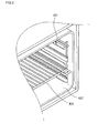
- Fig. 2 is a perspective view of a portion of a cavity of an electric oven range which is similar to the present invention, but does not form part of it.
- Fig. 2 shows a cavity 452 for holding food therein, a rack 424 resting inside the cavity 452 for placing foods on, and a checking portion fixed to an inner surface of the cavity 452 for removal by a user before implementing the pyrolysis function.
- the checking portion Before a user implements the pyrolysis function, the checking portion is used.
- the checking portion includes a checking screw 431 protruding outward from components that need to be removed from the cavity, and a sensor (not shown) disposed to the inside of the checking screw 431 on the surface of the cavity 452.
- the sensor senses the removal and allows the pyrolysis function to be carried out.
- the pyrolysis function may be programmed not to function. In other words, an unintended operation of the electric oven range through mistaken command inputs can be avoided.
- the checking screw 431 is only an exemplary component of the checking portion for a user to utilize, which may be replaced by another part not necessarily in the form of a screw.
- a bar, nut, or any number of devices that can be manipulated by a user may be used in lieu of the checking screw 431.
- the checking screw 431 is used again in the explanation below for the sake of convenience.
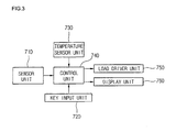
- Fig. 3 is a block diagram showing the structure of an electric oven range that has a pyrolysis function which is similar to the present invention but does not form part of it.
- the electric oven range having a pyrolysis function includes: an key input unit 720 for allowing the user to input commands, a sensor unit 710 for sensing whether the rack is present inside the oven and implementing the pyrolysis function when the user selects the pyrolysis mode through the key input unit 720, a temperature sensor unit 730 for detecting the temperature inside the oven, a control unit 740 for selectively controlling the temperature inside the oven according to feedback from the sensor unit 710, a display unit 760 for displaying the operational status of the oven according to a control signal from the control unit 740, and a load driver unit 750 for driving load components according to control signals from the control unit 740.
- the sensor unit 710 is intended to implement the pyrolysis function and includes the checking screw 431 and sensor (not shown) in Fig. 2 .
- the user turns on the power by pressing a power button on the key input unit 720, and selects a desired cooking setting by manipulating the control panel.
- the control unit 740 carries out the inputted cooking setting. Heat is emitted from elements through driving signals from the load driver unit 750, and the temperature sensor unit 730 senses the temperature inside the cavity in order to control the operation of the electric oven range.
- control unit 740 determines if conditions allow the implementation of the pyrolysis mode through feedback from the sensor unit 710.
- a second sensor unit 712 determines if the checking screw 431 for pyrolysis has been removed, and the control unit 74 controls the load driver unit 750 to implement the pyrolysis function.
- control unit 740 sends a control signal to the display unit 760 instructing it to display a message indicating that the pyrolysis checking screw 431 should be removed.
- the load driver unit 750 does not function at this time.
- the display unit 760 is to be understood in the general sense of a signalling unit for signalling to the user the operational status according to the control signal from the control unit. It can be a commonly known display screen capable of indicating symbols and/or characters or any arrangement of lights (LEDs) or other commonly known means suitable to indicate an operational status.
- LEDs lights
- the pyrolysis mode may be cancelled by pressing a cancellation button.
- Fig. 4 is a flowchart showing a method of controlling the pyrolysis function of an electric oven range similar to the present invention.
- step S101 the control unit determines whether the pyrolysis mode has been selected in step S102. Next, if the pyrolysis mode has been selected, as determined in step S102, it is determined if the pyrolysis checking screw 431 is present in step S103.
- step S103 If the checking screw is determined to be present in step S103, a message indicating that the checking screw should be removed is displayed in step S104. On the other hand, if the checking screw is found not to be present in step S103, the pyrolysis function is carried out in step S105.
- the plurality of heat sources such as heating elements inside the cavity are heated to maximum so that the temperature inside the cavity becomes extremely high.
- step S106 When the pyrolysis mode is completed in step S106, a message is displayed indicating its completion in step S107.
- step S102 If, in step S102, it is determined that the user has not selected the pyrolysis mode, other modes selected by the user are implemented in step S108.
- the pyrolysis checking screw needs to be removed in the electric oven range in order for the pyrolysis mode to function properly.
- the controlling method can also prevent the pyrolysis mode from operating if a user sets the pyrolysis mode by accidentally pressing buttons; and furthermore, if a user sets the pyrolysis mode without first removing the racks, brackets, and cooking containers from the cavity, the controlling method can prevent the electric oven range from operating according to the user's input commands, thereby preventing damage to the racks and like components.
- the checking screw for checking the operation of the pyrolysis mode when the mode is set
- the pyrolysis mode is not executed if the rack is present, so that the rack and other interior components are protected.
- the embodiment of the present invention has many similarities with theabove example, and includes two checking portions, being the pyrolysis checking screw and an additional rack screw for checking if the rack has been removed.
- two checking portions being the pyrolysis checking screw and an additional rack screw for checking if the rack has been removed.
- the same reference numerals will be used for parts identical to those in the example.
- Fig. 5 is a perspective view of a portion of a cavity of an electric oven range that has a pyrolysis function according to a embodiment of the present invention
- Fig. 6 is a block diagram showing the structure of an electric oven range according to the embodiment of the present invention.
- the cavity 452 of the electric oven range includes a pyrolysis checking screw 431 for a user to purposely remove before implementing the pyrolysis function, and a rack screw 432 for securing the rack 424.
- the rack screw 432 also has a sensor provided therewith for double-checking if the rack 424 has been removed by checking if the rack sensor 432 has been removed. Also, because the rack screw 432 functions to secure the rack 424, the latter can only be removed by removing the former.
- the sensor unit 710 includes a second sensor 712 for determining whether the pyrolysis checking screw 431 has been removed, and a first sensor 711 for determining whether the rack screw 432 has been removed, as shown in Fig. 6 . Because the first sensor 711 determines whether the rack screw 432 has been removed, it more reliably prevents damage to the rack 424.
- Fig. 7 is a flowchart showing the method of controlling the pyrolysis function of an electric oven range according to the embodiment of the present invention.
- control unit determines whether the pyrolysis mode has been selected in step S202.
- step S202 determines if the pyrolysis mode has been selected according to step S202. If the pyrolysis mode has been selected according to step S202, the control unit determines if the pyrolysis checking screw 431 is present in step S203. If the checking screw 431 is found to be present in step s203, a message indicating that the screw must be removed is outputted in step S204.
- step S203 if the checking screw 431 is found not to be present in step S203, the pyrolysis function is carried out in step S205 according to the settings.
- control unit determines in step S206 if the rack screw 432 is present in order to determine if the rack is present. If the rack is found to be present in step S206, a first temperature setting for the inside of the cavity is maintained in step S207, the first temperature setting being approximately 250°, which will not cause damage to the rack.
- step S208 When pyrolysis in step S208 at the first temperature setting is completed, "partial pyrolysis operation" is outputted in step S209. When the user views this outputted message, (s)he will realize that partial pyrolysis was implemented due to the presence of the rack in the oven.
- a second temperature setting is maintained inside the cavity in step S210 for full implementation of pyrolysis.
- the second temperature setting is approximately 450°, which can damage the rack. However, because the rack has already been removed from the cavity, no damage is incurred.
- step S211 When the operation is completed in step S211, the message, "normal pyrolysis operation" is displayed in step S212. Upon seeing this message, the user realizes that the pyrolysis function has ended.
- step S213 If the pyrolysis mode has not been selected by the user as sensed in step S202, other command settings inputted by the user are carried out in step S213.
- the pyrolysis function is implemented at a first temperature setting for the oven's interior, so that partial pyrolysis is performed in order to partially remove food deposits in the oven.
- the oven is more convenient to use.
- the display outputs messages, a user can more readily check the status of pyrolysis operation.
Landscapes
- Engineering & Computer Science (AREA)
- Chemical & Material Sciences (AREA)
- Combustion & Propulsion (AREA)
- Mechanical Engineering (AREA)
- General Engineering & Computer Science (AREA)
- Chemical Kinetics & Catalysis (AREA)
- Electric Stoves And Ranges (AREA)
Claims (17)
- Verfahren zum Steuern eines elektrischen Ofens für das Implementieren einer Pyrolysefunktion zum Reinigen eines Inneren eines Garraums (452), wobei das Steuerverfahren umfasst:(a) Bestimmen, ob ein erster Überprüfungsabschnitt (431,712) von einem Benutzer betätigt worden ist, wenn ein Pyrolysemodus ausgewählt wird,(a1) Bereitstellen einer Nachricht, den ersten Überprüfungsabschnitt (431,712) zu betätigen, wenn festgestellt wird, dass der erste Überprüfungsabschnitt (431,712) nicht betätigt worden ist, und(a2) Ausführen einer Pyrolyse, falls festgestellt wird, dass der erste Überprüfungsabschnitt (431,712) betätigt worden ist,
dadurch gekennzeichnet, dass das Verfahren die folgenden Schritte umfasst:(b) Bestimmen, ob ein zweiter Überprüfungsabschnitt (432, 711) durch einen Benutzer betätigt worden ist, wenn eine Pyrolyse durchgeführt wird, und(b1) Ausführen der Pyrolyse mit einer ersten Temperatureinstellung, falls festgestellt wird, dass der zweite Überprüfungsabschnitt (432,711) nicht betätigt worden ist, und(b2) Ausführen der Pyrolyse mit einer zweiten Temperatureinstellung, falls festgestellt wird, dass der zweite Überprüfungsabschnitt (432,711) betätigt worden ist. - Steuerverfahren nach Anspruch 1, wobei die Nachricht visuell angezeigt wird.
- Steuerverfahren nach Anspruch 1 oder 2, wobei die ersten und zweiten Überprüfungsabschnitte (431,712;432,711) im Inneren des Garraums (452) vorgesehen sind und von einem Benutzer entfernt werden können, und die Betätigung das Entfernen der Überprüfungsabschnitte (431,432) umfasst.
- Steuerverfahren nach einem der vorangehenden Ansprüche, ferner das Anzeigen einer Nachricht umfassend, welche eine Fertigstellung anzeigt, nachdem die Pyrolyse abgeschlossen ist.
- Steuerverfahren nach einem der vorangehenden Ansprüche, wobei der zweite Überprüfungsabschnitt (432,711) dazu dient, eine entfernbare Komponente (424) in dem Garraum (452) zu befestigen.
- Steuerverfahren nach einem der vorangehenden Ansprüche, wobei, wenn festgestellt wird, dass der erste Überprüfungsabschnitt (431,712) nicht betätigt worden ist, die Pyrolyse nicht durchgeführt wird und eine Nachricht angezeigt wird.
- Steuerverfahren nach einem der vorangehenden Ansprüche, wobei die Pyrolyse mit der zweiten Temperatureinstellung bei einer Temperatur durchgeführt wird, die für eine normale Pyrolyse erforderlich ist, wenn festgestellt wird, dass die ersten und zweiten Überprüfungsabschnitte (431,712;432,711) betätigt worden sind.
- Steuerverfahren nach Anspruch 7, ferner umfassend das Anzeigen einer Nachricht, die angibt, dass der Pyrolysemodus bei der für eine normale Pyrolyse erforderlichen Temperatur durchgeführt wurde.
- Steuerverfahren nach einem der vorangehenden Ansprüche in Kombination mit Anspruch 5, wobei die Pyrolyse mit der ersten Temperatureinstellung bei einer niedrigeren Temperatur durchgeführt wird, die der entfernbaren Komponente (424) in dem Garraum (452) keinen Schaden zufügt, wenn festgestellt wird, dass der erste Überprüfungsabschnitt (431,712) betätigt worden ist und der zweite Überprüfungsabschnitt (432,711) nicht betätigt worden ist.
- Steuerverfahren nach Anspruch 9, ferner umfassend das Anzeigen einer Nachricht, die angibt, dass eine Teilpyrolyse nach Abschluß der Pyrolyse bei der niedrigeren Temperatur durchgeführt worden ist.
- Steuerverfahren nach einem der vorangehenden Ansprüche, wobei der/die Überprüfungsabschnitt(e) eine Schraube (431, 432) aufweist/aufweisen, die durch Drehung zu betätigen ist, und die erforderliche Betätigung das Entfernen der Schraube (431,432) umfasst.
- Elektrischer Ofen mit:einer Tasten-Eingabeeinheit (720) zum Eingeben von Befehlen,einer Sensoreinheit (710) mit einem ersten Überprüfungsabschnitt (431,712) und einem zweiten Überprüfungsabschnitt (432,711), um abzutasten, ob ein Benutzer eine vorbestimmte erforderliche Betätigung durchgeführt hat, wenn ein Pyrolysemodus über die Tasten-Eingabeeinheit (720) ausgewählt wurde,einer Steuereinheit (740) zum selektiven Ausführen einer Pyrolyse entsprechend einer Rückkoppelung von der Sensoreinheit (710), undeiner Signalisierungseinheit (760), um dem Benutzer einen Betriebszustand entsprechend einem Steuersignal von der Steuereinheit (740) zu signalisieren,wobei die Steuereinheit (740) eingerichtet ist, eine Pyrolyse auszuführen, wenn ein Pyrolysemodus ausgewählt und festgestellt wurde, dass der erste Überprüfungsabschnitt (431,712) von einem Benutzer betätigt worden ist, dadurch gekennzeichnet, dass die Steuereinheit (740) eingerichtet ist, die Pyrolyse mit einer ersten Temperatureinstellung auszuführen, falls festgestellt wurde, dass der zweite Überprüfungsabschnitt (432,711) nicht betätigt worden ist, und die Pyrolyse mit einer zweiten Temperatureinstellung auszuführen, wenn festgestellt wurde, dass der zweite Überprüfungsabschnitt (432,711) betätigt worden ist.
- Elektrischer Ofen nach Anspruch 12, wobei der erste und zweite Überprüfungsabschnitt (431,712;432,711) in einem Inneren eines Garraums (452) vorgesehen sind, und von einem Benutzer entfernt werden können, und die vorbestimmte erforderliche Betätigung das Entfernen der Überprüfungsabschnitte (431,432) umfasst.
- Elektrischer Ofen nach Anspruch 13, wobei der/die Überprüfungsabschnitt(e) eine Schraube (431,432) umfasst/umfassen, die an einer Innenwand des Garraums (452) vorgesehen ist, und die erforderliche Betätigung das Entfernen der Schraube (431,432) umfasst.
- Elektrischer Ofen nach Anspruch 12, 13 oder 14, wobei die Signalisierungseinheit eine Anzeigeeinheit (760) aufweist, die eine Nachricht anzeigen kann, welche eine Betätigung des ersten Überprüfungsabschnitts (431,712) anfordert, wenn der erste Überprüfungsabschnitt (431,712) nicht betätigt worden ist.
- Elektrischer Ofen nach einem der Ansprüche 12 bis 15, wobei der zweite Überprüfungsabschnitt (432,711) einen Sensor (711) zum Abtasten einer Betätigung eines Elements aufweist, das dazu dient, eine entfernbare Komponente (424) innerhalb eines/des Hohlraums (452) des Ofens zu befestigen.
- Elektrischer Ofen nach einem der Ansprüche 12 bis 16, wobei die Signalisierungseinheit (760) eine Fertigstellungsnachricht ausgeben kann, nachdem die Pyrolyse beendet worden ist.
Applications Claiming Priority (2)
| Application Number | Priority Date | Filing Date | Title |
|---|---|---|---|
| KR1020040102798A KR100682673B1 (ko) | 2004-12-08 | 2004-12-08 | 파이로리시스 기능을 갖는 전기 오븐레인지 및 그 제어방법 |
| KR1020040102797A KR100682672B1 (ko) | 2004-12-08 | 2004-12-08 | 파이로리시스 기능을 갖는 전기 오븐레인지 및 그 제어방법 |
Publications (2)
| Publication Number | Publication Date |
|---|---|
| EP1669678A1 EP1669678A1 (de) | 2006-06-14 |
| EP1669678B1 true EP1669678B1 (de) | 2008-10-15 |
Family
ID=35810238
Family Applications (1)
| Application Number | Title | Priority Date | Filing Date |
|---|---|---|---|
| EP20050111093 Ceased EP1669678B1 (de) | 2004-12-08 | 2005-11-22 | Elektrischer Backofen und Methode zu seiner Steuerung im Pyrolyse-Betrieb |
Country Status (3)
| Country | Link |
|---|---|
| EP (1) | EP1669678B1 (de) |
| AU (1) | AU2005242178B2 (de) |
| DE (1) | DE602005010376D1 (de) |
Cited By (1)
| Publication number | Priority date | Publication date | Assignee | Title |
|---|---|---|---|---|
| US11959644B2 (en) | 2019-09-27 | 2024-04-16 | Ecolab Usa Inc. | Validation of addition of cleaning chemistry to self-cleaning oven |
Families Citing this family (3)
| Publication number | Priority date | Publication date | Assignee | Title |
|---|---|---|---|---|
| ATE456008T1 (de) * | 2007-11-26 | 2010-02-15 | Electrolux Home Prod Corp | Selbstreinigender backofen |
| ES2364009B1 (es) * | 2009-02-24 | 2012-09-14 | Bsh Electrodomésticos España, S.A. | Horno de cocción con sistema de limpieza pirolítica y elemento soporte bandeja para dicho horno. |
| US10060632B2 (en) * | 2013-10-02 | 2018-08-28 | Samsung Electronics Co., Ltd. | Cooking apparatus and method of controlling the same |
Family Cites Families (4)
| Publication number | Priority date | Publication date | Assignee | Title |
|---|---|---|---|---|
| US4862870A (en) * | 1988-12-21 | 1989-09-05 | General Electric Company | Bimetal lock arrangement for a self-cleaning oven latch |
| DE4215772C2 (de) * | 1992-05-13 | 1996-12-12 | Miele & Cie | Backofentür |
| US5543784A (en) * | 1993-11-30 | 1996-08-06 | Mendenhall; Donna M. | Oven occupancy warning apparatus |
| DE19954470B4 (de) * | 1999-11-12 | 2006-02-09 | AEG Hausgeräte GmbH | Vorrichtung und Verfahren zum Betreiben eines Garofens mit Pyrolysefunktion |
-
2005
- 2005-11-22 EP EP20050111093 patent/EP1669678B1/de not_active Ceased
- 2005-11-22 DE DE200560010376 patent/DE602005010376D1/de not_active Expired - Lifetime
- 2005-12-08 AU AU2005242178A patent/AU2005242178B2/en not_active Ceased
Cited By (1)
| Publication number | Priority date | Publication date | Assignee | Title |
|---|---|---|---|---|
| US11959644B2 (en) | 2019-09-27 | 2024-04-16 | Ecolab Usa Inc. | Validation of addition of cleaning chemistry to self-cleaning oven |
Also Published As
| Publication number | Publication date |
|---|---|
| EP1669678A1 (de) | 2006-06-14 |
| AU2005242178A1 (en) | 2006-06-22 |
| DE602005010376D1 (de) | 2008-11-27 |
| AU2005242178B2 (en) | 2010-06-03 |
Similar Documents
| Publication | Publication Date | Title |
|---|---|---|
| KR101609390B1 (ko) | 조리기기 | |
| US8334482B2 (en) | Cooking range with air circulation mechanism | |
| US9506657B2 (en) | Oven preheat boost using cooktop lockout | |
| CN101427077A (zh) | 高频加热装置 | |
| EP1669678B1 (de) | Elektrischer Backofen und Methode zu seiner Steuerung im Pyrolyse-Betrieb | |
| KR101630438B1 (ko) | 전기레인지 | |
| JP2008226750A (ja) | 電磁調理器 | |
| KR20060091857A (ko) | 전기 오븐레인지의 제어장치 및 방법 | |
| JP5264579B2 (ja) | 加熱調理器 | |
| JP4969351B2 (ja) | 誘導加熱調理器 | |
| KR100935330B1 (ko) | 오븐레인지의 도어 제어장치 및 방법 | |
| KR100963400B1 (ko) | 조리기기 및 그 제어방법 | |
| JP5358930B2 (ja) | 高周波加熱装置 | |
| JP2008071550A (ja) | 加熱調理器 | |
| KR20090115408A (ko) | 후드 겸용 전자레인지 및 그 제어방법 | |
| JP2006294433A (ja) | 誘導加熱調理器 | |
| KR100682673B1 (ko) | 파이로리시스 기능을 갖는 전기 오븐레인지 및 그 제어방법 | |
| CN101077266B (zh) | 加热烹调机 | |
| JP3913641B2 (ja) | 誘導加熱調理器 | |
| KR100682672B1 (ko) | 파이로리시스 기능을 갖는 전기 오븐레인지 및 그 제어방법 | |
| KR100709422B1 (ko) | 텔레스코픽 랙을 채용한 전기오븐레인지 및 그 제어방법 | |
| KR20100122024A (ko) | 조리기기 | |
| US20150075509A1 (en) | Oven appliance and method for operating an oven appliance | |
| US12007121B2 (en) | Safety control logic for a multi-pane door assembly of an oven appliance | |
| KR100700771B1 (ko) | 슬라이딩 타입의 백가드가 구비된 오븐레인지 |
Legal Events
| Date | Code | Title | Description |
|---|---|---|---|
| PUAI | Public reference made under article 153(3) epc to a published international application that has entered the european phase |
Free format text: ORIGINAL CODE: 0009012 |
|
| 17P | Request for examination filed |
Effective date: 20051123 |
|
| AK | Designated contracting states |
Kind code of ref document: A1 Designated state(s): AT BE BG CH CY CZ DE DK EE ES FI FR GB GR HU IE IS IT LI LT LU LV MC NL PL PT RO SE SI SK TR |
|
| AX | Request for extension of the european patent |
Extension state: AL BA HR MK YU |
|
| 17Q | First examination report despatched |
Effective date: 20070111 |
|
| AKX | Designation fees paid |
Designated state(s): DE FR GB IT |
|
| 17Q | First examination report despatched |
Effective date: 20070111 |
|
| GRAP | Despatch of communication of intention to grant a patent |
Free format text: ORIGINAL CODE: EPIDOSNIGR1 |
|
| GRAS | Grant fee paid |
Free format text: ORIGINAL CODE: EPIDOSNIGR3 |
|
| GRAA | (expected) grant |
Free format text: ORIGINAL CODE: 0009210 |
|
| AK | Designated contracting states |
Kind code of ref document: B1 Designated state(s): DE FR GB IT |
|
| REG | Reference to a national code |
Ref country code: GB Ref legal event code: FG4D |
|
| REF | Corresponds to: |
Ref document number: 602005010376 Country of ref document: DE Date of ref document: 20081127 Kind code of ref document: P |
|
| PLBE | No opposition filed within time limit |
Free format text: ORIGINAL CODE: 0009261 |
|
| STAA | Information on the status of an ep patent application or granted ep patent |
Free format text: STATUS: NO OPPOSITION FILED WITHIN TIME LIMIT |
|
| 26N | No opposition filed |
Effective date: 20090716 |
|
| PGFP | Annual fee paid to national office [announced via postgrant information from national office to epo] |
Ref country code: IT Payment date: 20131118 Year of fee payment: 9 |
|
| REG | Reference to a national code |
Ref country code: FR Ref legal event code: PLFP Year of fee payment: 11 |
|
| PG25 | Lapsed in a contracting state [announced via postgrant information from national office to epo] |
Ref country code: IT Free format text: LAPSE BECAUSE OF NON-PAYMENT OF DUE FEES Effective date: 20141122 |
|
| REG | Reference to a national code |
Ref country code: FR Ref legal event code: PLFP Year of fee payment: 12 |
|
| REG | Reference to a national code |
Ref country code: FR Ref legal event code: PLFP Year of fee payment: 13 |
|
| PGFP | Annual fee paid to national office [announced via postgrant information from national office to epo] |
Ref country code: FR Payment date: 20171011 Year of fee payment: 13 Ref country code: DE Payment date: 20171002 Year of fee payment: 13 |
|
| PGFP | Annual fee paid to national office [announced via postgrant information from national office to epo] |
Ref country code: GB Payment date: 20171002 Year of fee payment: 13 |
|
| REG | Reference to a national code |
Ref country code: DE Ref legal event code: R119 Ref document number: 602005010376 Country of ref document: DE |
|
| GBPC | Gb: european patent ceased through non-payment of renewal fee |
Effective date: 20181122 |
|
| PG25 | Lapsed in a contracting state [announced via postgrant information from national office to epo] |
Ref country code: DE Free format text: LAPSE BECAUSE OF NON-PAYMENT OF DUE FEES Effective date: 20190601 Ref country code: FR Free format text: LAPSE BECAUSE OF NON-PAYMENT OF DUE FEES Effective date: 20181130 |
|
| PG25 | Lapsed in a contracting state [announced via postgrant information from national office to epo] |
Ref country code: GB Free format text: LAPSE BECAUSE OF NON-PAYMENT OF DUE FEES Effective date: 20181122 |