EP1669715A1 - Dispositif de contrôle de la géométrie - Google Patents
Dispositif de contrôle de la géométrie Download PDFInfo
- Publication number
- EP1669715A1 EP1669715A1 EP06111762A EP06111762A EP1669715A1 EP 1669715 A1 EP1669715 A1 EP 1669715A1 EP 06111762 A EP06111762 A EP 06111762A EP 06111762 A EP06111762 A EP 06111762A EP 1669715 A1 EP1669715 A1 EP 1669715A1
- Authority
- EP
- European Patent Office
- Prior art keywords
- measuring
- camera
- heads
- measuring heads
- targets
- Prior art date
- Legal status (The legal status is an assumption and is not a legal conclusion. Google has not performed a legal analysis and makes no representation as to the accuracy of the status listed.)
- Granted
Links
Images


Classifications
-
- G—PHYSICS
- G01—MEASURING; TESTING
- G01B—MEASURING LENGTH, THICKNESS OR SIMILAR LINEAR DIMENSIONS; MEASURING ANGLES; MEASURING AREAS; MEASURING IRREGULARITIES OF SURFACES OR CONTOURS
- G01B11/00—Measuring arrangements characterised by the use of optical techniques
- G01B11/26—Measuring arrangements characterised by the use of optical techniques for measuring angles or tapers; for testing the alignment of axes
- G01B11/275—Measuring arrangements characterised by the use of optical techniques for measuring angles or tapers; for testing the alignment of axes for testing wheel alignment
- G01B11/2755—Measuring arrangements characterised by the use of optical techniques for measuring angles or tapers; for testing the alignment of axes for testing wheel alignment using photoelectric detection means
-
- G—PHYSICS
- G01—MEASURING; TESTING
- G01B—MEASURING LENGTH, THICKNESS OR SIMILAR LINEAR DIMENSIONS; MEASURING ANGLES; MEASURING AREAS; MEASURING IRREGULARITIES OF SURFACES OR CONTOURS
- G01B11/00—Measuring arrangements characterised by the use of optical techniques
- G01B11/26—Measuring arrangements characterised by the use of optical techniques for measuring angles or tapers; for testing the alignment of axes
- G01B11/275—Measuring arrangements characterised by the use of optical techniques for measuring angles or tapers; for testing the alignment of axes for testing wheel alignment
-
- G—PHYSICS
- G01—MEASURING; TESTING
- G01B—MEASURING LENGTH, THICKNESS OR SIMILAR LINEAR DIMENSIONS; MEASURING ANGLES; MEASURING AREAS; MEASURING IRREGULARITIES OF SURFACES OR CONTOURS
- G01B2210/00—Aspects not specifically covered by any group under G01B, e.g. of wheel alignment, caliper-like sensors
- G01B2210/10—Wheel alignment
- G01B2210/12—Method or fixture for calibrating the wheel aligner
-
- G—PHYSICS
- G01—MEASURING; TESTING
- G01B—MEASURING LENGTH, THICKNESS OR SIMILAR LINEAR DIMENSIONS; MEASURING ANGLES; MEASURING AREAS; MEASURING IRREGULARITIES OF SURFACES OR CONTOURS
- G01B2210/00—Aspects not specifically covered by any group under G01B, e.g. of wheel alignment, caliper-like sensors
- G01B2210/10—Wheel alignment
- G01B2210/14—One or more cameras or other optical devices capable of acquiring a two-dimensional image
- G01B2210/143—One or more cameras on each side of a vehicle in the main embodiment
-
- G—PHYSICS
- G01—MEASURING; TESTING
- G01B—MEASURING LENGTH, THICKNESS OR SIMILAR LINEAR DIMENSIONS; MEASURING ANGLES; MEASURING AREAS; MEASURING IRREGULARITIES OF SURFACES OR CONTOURS
- G01B2210/00—Aspects not specifically covered by any group under G01B, e.g. of wheel alignment, caliper-like sensors
- G01B2210/10—Wheel alignment
- G01B2210/30—Reference markings, reflector, scale or other passive device
-
- G—PHYSICS
- G01—MEASURING; TESTING
- G01B—MEASURING LENGTH, THICKNESS OR SIMILAR LINEAR DIMENSIONS; MEASURING ANGLES; MEASURING AREAS; MEASURING IRREGULARITIES OF SURFACES OR CONTOURS
- G01B2210/00—Aspects not specifically covered by any group under G01B, e.g. of wheel alignment, caliper-like sensors
- G01B2210/10—Wheel alignment
- G01B2210/30—Reference markings, reflector, scale or other passive device
- G01B2210/303—Reference markings, reflector, scale or other passive device fixed to the ground or to the measuring station
Definitions
- the invention relates to a wheel alignment device with measuring heads for determining the wheel positions of the wheels of a motor vehicle on a measuring station, wherein each measuring head has at least one camera which is aligned with a positioned in the field of view of the camera, in a fixed relationship to the wheel of the motor vehicle measuring target, and wherein the images of the camera are evaluated by an evaluation unit in order to determine the spatial position of the measuring target and thus of the wheel with respect to the position of the camera or of the measuring head.
- non-contact chassis or wheel alignment devices are known, for example, from EP 0 895 056, EP 0 943 890 and DE 197 57 763 A1.
- the measuring heads which are used to determine the wheel positions of the wheels of the motor vehicle on the measuring station, must be aligned with respect to each other before the actual measurement, which is a problem in practice.
- the alignment of the measuring heads takes place with one another in that reference targets are present on the measuring station with the aid of which the measuring heads are to be aligned. Since the reference star marks are placed in front of the vehicle at the measuring station, the distance from the reference targets to the measuring heads at the rear wheels is very wide, so that it is difficult to achieve the required accuracy in the calibration, the measuring heads.
- the present invention seeks to provide a suspension or Achsver limps Ranunasuccinsky, which does not require stationary reference system and in which the calibration with as little calibration work and components is possible.
- the Fahrtechnikvermssungs worn invention is characterized by an optical, integrated in the measuring heads reference system for calibrating the measuring heads of the wheel alignment with respect to the position of the measuring heads to each other.
- an optical, integrated in the measuring heads reference system for calibrating the measuring heads of the wheel alignment with respect to the position of the measuring heads to each other.
- the reference system includes a reference camera on one of the measuring heads on one side of the motor vehicle and a reference target on the opposite side of the same vehicle head and reference targets on the inside of a front and a rear measuring head in the field of view the measuring cameras lie on the opposite measuring heads.
- This arrangement has the advantage that the measuring heads are freely positionable depending on the wheelbase and track, the measuring cameras in the measurement, the measuring targets in the field of view and the measuring and reference cameras the measuring or reference targets in the field of vision, if no vehicle in the tester is available.
- the measuring heads are diagonally exchangeable, and self-checking can be done by rounding. For calibration, the vehicle must be moved out of the measuring field.
- An advantageous embodiment of the chassis measuring device is characterized in that the reference system has a reference camera on one of the front measuring heads and a reference target on the opposite measuring head, with camera and reference target in front or behind the motor vehicle, and that the reference system further comprises a reference camera in one of having lateral measuring heads and a reference target on the opposite side of the same vehicle side measuring head.
- the measuring heads are freely positionable depending on the wheelbase and track, as long as they have each other in view. Only three reference cameras and targets are needed to build the reference system.
- An advantageous embodiment of the wheel alignment measuring device is characterized in that further arranged on the rear measuring heads a reference camera on a measuring head and a reference target on the opposite measuring head. It is advantageous that the measuring heads are freely positionable depending on the wheelbase and track, as long as they have each other in the field of view.
- the measuring heads are diagonally interchangeable, and it is a self-control of Fahrwerkmeß worn by Rundumunk of the reference system possible, as is the case with the so-called Achtgeber Achsmeßtechnikn.
- An advantageous embodiment of the chassis measuring device according to the invention is characterized by an optical beam splitter or mirror system, which is arranged between each reference target and a respective measuring camera such that the Referenztargts be observed by the measuring camera. Since reference cameras are replaced by an optical beam splitter or mirror system by this arrangement, this arrangement has the advantage that a reference camera is saved by the beam splitter or mirror system, which makes the entire device cheaper.
- An advantageous embodiment of the wheel alignment measuring device is characterized in that the reference system at the lateral measuring heads per a CCD reference camera, which is directed to the opposite measuring head on the same side, and arranged at the opposite measuring head per at least two LED elements as reference targets , And that at the front and / or rear measuring heads each additional CCD reference cameras and at the opposite measuring heads LED elements are arranged as reference targets.
- the reference system at the lateral measuring heads per a CCD reference camera which is directed to the opposite measuring head on the same side, and arranged at the opposite measuring head per at least two LED elements as reference targets , And that at the front and / or rear measuring heads each additional CCD reference cameras and at the opposite measuring heads LED elements are arranged as reference targets.
- the measuring heads are freely positionable and diagonally exchangeable.
- An advantageous embodiment of the chassis measuring device according to the invention is characterized in that three LED elements are provided as a reference target.
- three LED elements are provided as a reference target.
- only one CCD reference camera per measuring head is necessary, which in turn leads to cost savings.
- An advantageous embodiment of the chassis measuring device according to the invention is characterized in that the reference system has reference targets on the inside of the measuring heads and an optical reference unit between the reference targets, which is aligned with the reference targets.
- a central reference unit for calibration of the wheel alignment device is provided, which is available at any time after their installation and calibration.
- the actual measuring heads for measuring the wheel positions can be carried out relatively easily.
- the depth of field of the measuring system and reference system can be set and calibrated separately, so that a recalibration is relatively rarely required.
- the measuring heads are again diagonally exchangeable in this arrangement.
- An advantageous embodiment of the chassis measuring device according to the invention is characterized in that the reference optics comprises four each directed to the reference targets cameras. This arrangement has the advantage that only a single adjustment of the reference system is necessary, and that no moving parts are present in the reference unit.
- An advantageous embodiment of the chassis measuring device according to the invention is characterized in that the reference optics comprises a reference camera and a mirror or beam splitter system which directs the field of view of the reference camera to the reference targets.
- the reference optics comprises a reference camera and a mirror or beam splitter system which directs the field of view of the reference camera to the reference targets.
- An advantageous embodiment of the wheel alignment measuring device is characterized in that the reference optics comprises a rotatably mounted reference camera.
- the actual measuring heads for measuring the wheels can be made relatively simple, and the depth of field of the measuring system and reference system can be set separately and calibrated. Since only one camera for the Reference unit is required, a cost savings is achieved against the previous embodiment.
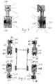
- Fig. 1 shows a wheel alignment device with a built-in measuring heads reference system.
- the measuring targets are observed by measuring cameras 42, 44, 46 and 48, respectively, when the wheel alignment is performed.
- the measuring cameras 42, 44, 46, 48 are located in measuring heads 52, 54, 56, 58.
- the front of the vehicle 32 like the front of the vehicles in the following embodiments, in the drawings directed upward, so that the upper measuring heads are referred to as front measuring heads or measuring heads on the front wheels and the lower measuring heads as rear measuring heads or measuring heads on the rear wheels ,
- reference targets 60, 61 are arranged, which are each in the view of the measuring camera 44 and 48, if no vehicle is present in the measuring station.
- the reference system is completed by reference cameras 62, 64 in the measuring heads 54, 56 and reference targets 66, 68 at the measuring heads 58, 54.
- the targets 66, 68 are in the view of the reference cameras 64 and 62, respectively.
- a self-calibration of the measuring heads is carried out before the wheel alignment.
- the position and angular position of the individual measuring heads can be determined relative to each other as long as no motor vehicle is on the measuring station. After calibration, the vehicle is then retracted and measured in the measuring station.
- FIG. 2 shows a wheel alignment device with additional optical device to the measuring heads.
- a vehicle 122 comprises measuring targets 124, 126, 128, 130 at its wheels, the measuring targets being in the view of measuring cameras 132, 134, 136 and 138, respectively.
- the measuring cameras are arranged in measuring heads 142, 144, 146, 148.
- reference cameras 150, 152 are arranged, the reference targets 154, 156 in the field of view, which are arranged at the rear measuring heads 148 and 146, respectively.
- About boom 158, 160 144 and 142, a reference camera 162 and a reference target 164 are arranged at the front measuring heads.
- the reference cameras 150, 152 establish the reference between the front measuring heads 142, 144 and the rear measuring heads 146, 148 via the reference targets 154, 156, while the reference camera 162 and the reference target 164 relate the reference transversely to the direction of travel of the vehicle produces lateral measuring heads.
- the self-calibration of the measuring heads takes place during a wheel alignment.
- FIG. 3 shows a further embodiment of the embodiment of FIG. 2.
- the wheel alignment device according to FIG. 3 has two additional arms 166, 168 on the rear measuring heads 148 and 146, respectively, on which a reference camera 170 and a reference target 172 are arranged. With this arrangement, a so-called round measurement is possible, so that the adjustment of the wheel alignment device can be subjected to a self-control.
- FIG. 4 shows a mirror system by which a camera is saved or replaced by the mirror system per measuring head of the type shown in FIG.
- the camera 162 of FIG. 3 is saved
- the measuring head 142 the camera 150 of FIG. 3 is saved.
- a mirror system 174 is arranged in the measuring head 144 on the arm 158
- a tilting mirror system 176 is provided in the measuring head 144 itself. which switches the beam path of the measuring camera 134 from a beam path to the mirror system 174 to a beam path to the opposite Meßtarget.
- a tilting mirror system 178 is provided, which switches the beam path of the measuring camera 132 between a beam path to the measuring target and a beam path to the reference target.
- the arrangement of the wheel alignment device according to FIG. 5 corresponds to that of FIG. 3, wherein the measuring cameras for measuring the individual wheels are not shown in FIG. 5 for the sake of simplicity.
- the front measuring heads 142, 144 boom 180, 182, to each of which a reference camera 184, 186, consisting of CCD lines, and two LED elements 188, 190 and 192, 194.
- the LED elements 188 , 190 bfw. 192,194 are respectively arranged in the field of view of the reference cameras 186 and 184, respectively.
- the angular position of the measuring heads 142, 144 can be determined transversely to the direction of travel of the vehicle in a known manner.
- each reference cameras CCD lines 198, 200, 202, 204 and LED elements 206, 208; 210, 212; 214, 216; 218, 220 are arranged, which are each in the field of view of the opposite reference camera.
- a corresponding arrangement to the arrangement on the front side is also provided on brackets 222, 224 on the rear measuring heads 146, 148.
- a reference camera (CCD line) 226 is provided on the measuring head 146 and a reference camera 228 is provided on the measuring head 148.
- In the field of view of the reference camera 126 are two LED elements 230, 232, and in the field of view of the reference camera 228 are two LED elements 234, 236.
- the fact that two LED elements each face a reference camera the distance between the measuring heads can be determined to each other , The position of each measuring head to the vertical can be determined by a pendulum system. With this arrangement, it is advantageous that simple line scan cameras can be used for the reference cameras and LED elements. Furthermore, the measuring heads can be freely positioned and replaced diagonally.
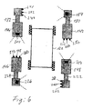
- FIG. 6 is another embodiment of the example of FIG. 5, wherein instead of two LED elements, three LED elements per reference camera are provided. This can ever account for one reference camera per measuring head.
- the reference camera 184 on the boom 180 are three LED elements 240, 242, 244 on the boom 182 of the measuring head 144th across from.
- the reference camera 200 on the measuring head 144 are opposite to three LED elements 246, 248, 250 on the measuring head 246.
- the reference camera 204 on the measuring head 148 are opposed by three LED elements 252, 254, 256.
- the reference camera 226 on the boom 224 are opposed by three LED elements 258, 260, 262 on the boom 222.
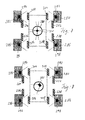
- FIG. 7 shows a wheel alignment device with an optical reference unit 270, which is arranged between reference targets 272, 274, 276, 280 approximately in the center of the measuring device.
- the reference targets are arranged on the inside of the measuring heads 280, 282, 284, 286.
- the reference unit 270 comprises either four stationary cameras or a camera with additional mirror optics to detect all reference targets on the measuring heads without rotation of the reference unit for calibration.
- FIG. 8 shows a modified embodiment of the device according to FIG. 7, wherein the reference unit 270 has a rotatably mounted camera 290, with which the reference targets 272, 274, 276, 278 can be observed.
- measuring cameras 292, 294, 296, 298 are provided which respectively detect measuring targets 302, 304, 306, 308 which are arranged on the wheels of a motor vehicle 310.
Landscapes
- Physics & Mathematics (AREA)
- General Physics & Mathematics (AREA)
- Length Measuring Devices By Optical Means (AREA)
Applications Claiming Priority (2)
| Application Number | Priority Date | Filing Date | Title |
|---|---|---|---|
| DE10043354A DE10043354A1 (de) | 2000-09-02 | 2000-09-02 | Fahrwerkvermessungseinrichtung |
| EP01120596A EP1184640B1 (fr) | 2000-09-02 | 2001-08-29 | Dispositif de mesure de la géométrie d' un véhicule |
Related Parent Applications (1)
| Application Number | Title | Priority Date | Filing Date |
|---|---|---|---|
| EP01120596A Division EP1184640B1 (fr) | 2000-09-02 | 2001-08-29 | Dispositif de mesure de la géométrie d' un véhicule |
Publications (2)
| Publication Number | Publication Date |
|---|---|
| EP1669715A1 true EP1669715A1 (fr) | 2006-06-14 |
| EP1669715B1 EP1669715B1 (fr) | 2008-08-13 |
Family
ID=7654808
Family Applications (2)
| Application Number | Title | Priority Date | Filing Date |
|---|---|---|---|
| EP01120596A Expired - Lifetime EP1184640B1 (fr) | 2000-09-02 | 2001-08-29 | Dispositif de mesure de la géométrie d' un véhicule |
| EP06111762A Expired - Lifetime EP1669715B1 (fr) | 2000-09-02 | 2001-08-29 | Dispositif de contrôle de la géométrie d'un chassis |
Family Applications Before (1)
| Application Number | Title | Priority Date | Filing Date |
|---|---|---|---|
| EP01120596A Expired - Lifetime EP1184640B1 (fr) | 2000-09-02 | 2001-08-29 | Dispositif de mesure de la géométrie d' un véhicule |
Country Status (3)
| Country | Link |
|---|---|
| US (1) | US6690456B2 (fr) |
| EP (2) | EP1184640B1 (fr) |
| DE (3) | DE10043354A1 (fr) |
Cited By (1)
| Publication number | Priority date | Publication date | Assignee | Title |
|---|---|---|---|---|
| US7774946B2 (en) | 2006-08-04 | 2010-08-17 | Fasep 2000 S.R.L. | Method and device for non-contact measurement of the alignment of motor vehicle wheels |
Families Citing this family (67)
| Publication number | Priority date | Publication date | Assignee | Title |
|---|---|---|---|---|
| BE1013152A3 (nl) * | 1999-11-24 | 2001-10-02 | Krypton Electronic Eng Nv | Werkwijze voor het bepalen van het dynamisch gedrag van een voertuig op een testbank. |
| US6968282B1 (en) | 2000-05-22 | 2005-11-22 | Snap-On Incorporated | Self-calibrating, multi-camera machine vision measuring system |
| EP1266188B1 (fr) | 2000-03-23 | 2006-05-17 | Snap-on Incorporated | Dispositif et procede de calibration de la position relative entre deux apparaeils de mesure d'un systeme de mesure |
| JP2004530889A (ja) | 2001-06-15 | 2004-10-07 | スナップ − オン テクノロジーズ,インコーポレイテッド | 自動較正位置決定システム |
| US7062861B2 (en) * | 2001-06-28 | 2006-06-20 | Snap-On Incorporated | Self-calibrating position determination system and user interface |
| DE60234308D1 (de) * | 2002-02-04 | 2009-12-24 | Corghi Spa | Vorrichtung zur Messung der charakteristischen Lageparameter eines Kraftfahrzeuges |
| US7336350B2 (en) * | 2002-05-15 | 2008-02-26 | Hunter Engineering Company | Wheel alignment apparatus and method utilizing three-dimensional imaging |
| US6871409B2 (en) * | 2002-12-18 | 2005-03-29 | Snap-On Incorporated | Gradient calculating camera board |
| US8306696B2 (en) * | 2003-04-17 | 2012-11-06 | Driveright Holdings, Ltd. | Method and system for aligning a vehicle with an artificial horizon |
| US20050005461A1 (en) * | 2003-06-25 | 2005-01-13 | Henry Rohrig | Truck alignment system |
| US7164472B2 (en) | 2003-10-09 | 2007-01-16 | Hunter Engineering Company | Common reference target machine vision wheel alignment system |
| DE102004013441A1 (de) | 2004-03-18 | 2005-10-13 | Beissbarth Gmbh | Meßverfahren und Meßgerät zur Bestimmung der räumlichen Lage einer Radfelge sowie Fahrwerkvermessungseinrichtung |
| US7525654B2 (en) * | 2004-10-20 | 2009-04-28 | Duquesne University Of The Holy Spirit | Tunable laser-based chemical imaging system |
| US20060152711A1 (en) * | 2004-12-30 | 2006-07-13 | Dale James L Jr | Non-contact vehicle measurement method and system |
| US7369222B2 (en) * | 2005-05-13 | 2008-05-06 | Snap-On Technologies, Inc. | Wheel aligner measurement module attachment system |
| US7583372B2 (en) * | 2005-06-01 | 2009-09-01 | Hunter Engineering Company | Machine vision vehicle wheel alignment image processing methods |
| US7454841B2 (en) * | 2005-11-01 | 2008-11-25 | Hunter Engineering Company | Method and apparatus for wheel alignment system target projection and illumination |
| DE102005060073B4 (de) * | 2005-12-15 | 2008-02-14 | Beissbarth Gmbh | Mess- bzw. Referenzeinheit und Fahrwerkvermessungssystem damit |
| DE102005063050A1 (de) * | 2005-12-29 | 2007-07-05 | Robert Bosch Gmbh | Verfahren und Vorrichtung zur berührungslosen Messung der Achsgeometrie |
| US7710555B2 (en) | 2006-06-27 | 2010-05-04 | Burke E. Porter Machinery Company | Apparatus and method for determining the orientation of an object such as vehicle wheel alignment |
| US7313869B1 (en) * | 2006-07-18 | 2008-01-01 | Snap-On Incorporated | Vehicle wheel alignment system and methodology |
| DE102006041822A1 (de) * | 2006-09-06 | 2008-03-27 | Beissbarth Gmbh | Verfahren zur Fahrwerksmessung eines Kraftfahrzeugs, Fahrwerksvermessungseinrichtung sowie Kraftfahrzeugprüfstrasse |
| DE102006041821A1 (de) * | 2006-09-06 | 2008-03-27 | Beissbarth Gmbh | Verfahren zur relativen Positionierung eines Messgegenstands und eines Kraftfahrzeugs zu einem Messgerät sowie Messgerät und Fahrwerksvermessungseinrichtung |
| US7864309B2 (en) | 2007-05-04 | 2011-01-04 | Burke E. Porter Machinery Company | Non contact wheel alignment sensor and method |
| US7684026B2 (en) * | 2007-07-27 | 2010-03-23 | Snap-On Incorporated | Fault tolerant wheel alignment head and system |
| US7640673B2 (en) * | 2007-08-01 | 2010-01-05 | Snap-On Incorporated | Calibration and operation of wheel alignment systems |
| CN103453857B (zh) * | 2007-08-31 | 2017-12-22 | 实耐宝公司 | 车轮定位系统和方法 |
| CN103226010B (zh) * | 2007-08-31 | 2016-08-10 | 实耐宝公司 | 车轮定位系统和方法 |
| CN103217129A (zh) * | 2007-08-31 | 2013-07-24 | 实耐宝公司 | 车轮定位系统和方法 |
| DE102007047424A1 (de) | 2007-10-04 | 2009-04-09 | Robert Bosch Gmbh | Kraftfahrzeugbauteil-Vermessungssystem, Verwendung sowie Verfahren |
| EP2232355B1 (fr) * | 2007-11-07 | 2012-08-29 | N-Trig Ltd. | Détection multipoint mise en oeuvre sur un numériseur à détection de point unique |
| DE102008006329A1 (de) | 2008-01-28 | 2009-07-30 | Robert Bosch Gmbh | Verfahren und Vorrichtung zum Überprüfen der Referenzierung von Messköpfen eines Fahrwerksvermessungssystems |
| DE102008000833A1 (de) * | 2008-03-26 | 2009-10-01 | Robert Bosch Gmbh | Messkopf für ein Fahrwerksvermessungssystem, Fahrwerksvermessungssystem sowie Verfahren zum Bestimmen der Lageparameter von Messköpfen eines Fahrwerksvermessungssystems |
| DE102008001339A1 (de) | 2008-04-23 | 2009-10-29 | Robert Bosch Gmbh | Verfahren und Vorrichtung zur Fahrwerksvermessung |
| FR2930986B1 (fr) * | 2008-05-07 | 2010-06-11 | Actia Muller | Procede et dispositif de controle de vehicule a deux roues |
| US8650766B2 (en) * | 2008-09-12 | 2014-02-18 | Robert Bosch Gmbh | Target system, set of target systems and device for optically aligning an axle |
| DE102008042018A1 (de) * | 2008-09-12 | 2010-03-18 | Robert Bosch Gmbh | Verfahren zum Justieren oder Kalibrieren eines Fahrzeugumfeldsensors sowie Fahrzeugumfeldsensor-Justier- oder Kalibrier-Anordnung |
| DE102009028796A1 (de) | 2008-09-12 | 2010-04-15 | Robert Bosch Gmbh | Fahrwerksvermessungseinrichtung mit Referenziereinrichtung |
| DE102010040655A1 (de) | 2010-09-13 | 2012-03-15 | Robert Bosch Gmbh | Verfahren und Vorrichtung zum Kalibrieren eines Referenzsystems zur Fahrzeugvermessung |
| DE102011086548A1 (de) | 2011-05-24 | 2012-11-29 | Robert Bosch Gmbh | Vorrichtung und Verfahren zur Fahrwerksvermessung eines Kraftfahrzeugs |
| ITMI20111695A1 (it) | 2011-09-21 | 2013-03-22 | Cemb S P A | Dispositivo e procedimento di misura delle dimensioni e degli angoli caratteristici di ruote, sterzo e telaio di veicoli in genere. |
| DE102012206212A1 (de) | 2012-04-16 | 2013-10-17 | Robert Bosch Gmbh | Verfahren zur Bestimmung der Orientierung mindestens einer Fahrschiene eines Messplatzes und Vorrichtung zur Durchführung des Verfahrens |
| WO2014033086A1 (fr) * | 2012-08-29 | 2014-03-06 | Robert Bosch Gmbh | Appareil de synchronisation de caméras dans un système d'alignement de roues de véhicule et procédé associé |
| DE102013211207A1 (de) | 2013-06-14 | 2014-12-18 | Robert Bosch Gmbh | Vorrichtung und Verfahren zum Referenzieren von Messwertaufnehmern zur Fahrzeugvermessung |
| DE102014204686A1 (de) * | 2014-03-13 | 2015-09-17 | Robert Bosch Gmbh | Verfahren und Vorrichtung zur Bildaufnahme in der Fahrzeugvermessung |
| CN106662435A (zh) * | 2014-06-06 | 2017-05-10 | Cemb股份公司 | 在诊断、维护或监测操作中测定车辆的至少一个元件的至少一个参数特征的设备和方法 |
| DE102014219109A1 (de) | 2014-09-23 | 2016-03-24 | Robert Bosch Gmbh | Referenzsystem und Messwertaufnehmer zum Einsatz in der Fahrzeugvermessung |
| CN105136484A (zh) * | 2015-06-02 | 2015-12-09 | 深圳科澳汽车科技有限公司 | 轴间四轮定位检测装置及检测方法 |
| CN109923371B (zh) | 2016-08-16 | 2021-11-26 | 实耐宝公司 | 车轮定位方法和系统 |
| WO2018060963A1 (fr) | 2016-09-30 | 2018-04-05 | Burke E. Porter Machinery Company | Procédé et système de mesure d'alignement de roues pour roues de véhicule |
| CN106813599B (zh) * | 2017-03-23 | 2018-12-21 | 深圳市鹰眼在线电子科技有限公司 | 汽车摄像测量组件与汽车三维四轮定位方法及系统 |
| US11243074B2 (en) | 2018-04-30 | 2022-02-08 | BPG Sales and Technology Investments, LLC | Vehicle alignment and sensor calibration system |
| US11781860B2 (en) | 2018-04-30 | 2023-10-10 | BPG Sales and Technology Investments, LLC | Mobile vehicular alignment for sensor calibration |
| US11597091B2 (en) | 2018-04-30 | 2023-03-07 | BPG Sales and Technology Investments, LLC | Robotic target alignment for vehicle sensor calibration |
| US12385766B2 (en) | 2018-04-30 | 2025-08-12 | BPG Sales and Technology Investments, LLC | Vehicular alignment for sensor calibration |
| US11835646B2 (en) | 2018-04-30 | 2023-12-05 | BPG Sales and Technology Investments, LLC | Target alignment for vehicle sensor calibration |
| HUE067153T2 (hu) | 2018-04-30 | 2024-10-28 | Bpg Sales And Tech Investments Llc | Jármûbeállítás érzékelõ kalibrálásához |
| CN108917690B (zh) * | 2018-05-29 | 2020-08-28 | 深圳先进技术研究院 | 一种汽车主销角的计算方法及测量装置 |
| JP7000254B2 (ja) * | 2018-06-01 | 2022-01-19 | トヨタ自動車株式会社 | ホイールアライメント調整システム |
| CN112639403B (zh) | 2018-09-13 | 2025-04-04 | 实耐宝公司 | 使用驱动方向计算具有提高精度和无停止定位的机动车辆对准器 |
| CN109323871B (zh) * | 2018-10-28 | 2020-08-07 | 吉林大学 | 开槽球柱销定向弧形臂单体四轮定位仪检定装置 |
| CN109883326A (zh) * | 2019-03-29 | 2019-06-14 | 湖南省鹰眼在线电子科技有限公司 | 一种摄像测量式汽车三维四轮定位方法、系统及介质 |
| WO2021220169A1 (fr) | 2020-04-27 | 2021-11-04 | BPG Sales and Technology Investments, LLC | Capteur et procédé d'orientation et d'alignement de véhicule sans contact |
| CN115702322A (zh) | 2020-06-15 | 2023-02-14 | 实耐宝公司 | 用于校准和对准汽车传感器的设备及方法 |
| CN111537015A (zh) * | 2020-06-16 | 2020-08-14 | 深圳市道通科技股份有限公司 | 一种车辆测量设备 |
| CN111879261A (zh) * | 2020-08-13 | 2020-11-03 | 深圳市道通科技股份有限公司 | 一种相机组件、车轮定位系统以及车轮定位方法 |
| EP4285141A4 (fr) | 2021-01-28 | 2024-12-25 | BPG Sales and Technology Investments, LLC | Système d'alignement de cible et procédé d'étalonnage de capteur |
Citations (2)
| Publication number | Priority date | Publication date | Assignee | Title |
|---|---|---|---|---|
| US4931964A (en) * | 1984-09-07 | 1990-06-05 | Fmc Corporation | Vehicle wheel alignment apparatus and method |
| EP1003011A1 (fr) * | 1998-11-20 | 2000-05-24 | Compagnie Europeenne d'Equipements de Garage | Détermination optique des positions relatives d'objets dans l'espace |
Family Cites Families (4)
| Publication number | Priority date | Publication date | Assignee | Title |
|---|---|---|---|---|
| DE2948573A1 (de) * | 1979-12-03 | 1981-06-04 | Siemens AG, 1000 Berlin und 8000 München | Verfahren und anordnung zur beruehrungslosen achsvermessung an kraftfahrzeugen |
| US5531030A (en) * | 1993-09-17 | 1996-07-02 | Fmc Corporation | Self-calibrating wheel alignment apparatus and method |
| EP1266188B1 (fr) * | 2000-03-23 | 2006-05-17 | Snap-on Incorporated | Dispositif et procede de calibration de la position relative entre deux apparaeils de mesure d'un systeme de mesure |
| EP1309832B1 (fr) * | 2000-08-14 | 2008-10-22 | Snap-on Incorporated | Système de mesure 3D à auto-etalonnage pour aligner les roues d'un véhicule |
-
2000
- 2000-09-02 DE DE10043354A patent/DE10043354A1/de not_active Withdrawn
-
2001
- 2001-08-29 EP EP01120596A patent/EP1184640B1/fr not_active Expired - Lifetime
- 2001-08-29 DE DE50114230T patent/DE50114230D1/de not_active Expired - Lifetime
- 2001-08-29 DE DE50112589T patent/DE50112589D1/de not_active Expired - Lifetime
- 2001-08-29 EP EP06111762A patent/EP1669715B1/fr not_active Expired - Lifetime
- 2001-08-31 US US09/945,440 patent/US6690456B2/en not_active Expired - Lifetime
Patent Citations (2)
| Publication number | Priority date | Publication date | Assignee | Title |
|---|---|---|---|---|
| US4931964A (en) * | 1984-09-07 | 1990-06-05 | Fmc Corporation | Vehicle wheel alignment apparatus and method |
| EP1003011A1 (fr) * | 1998-11-20 | 2000-05-24 | Compagnie Europeenne d'Equipements de Garage | Détermination optique des positions relatives d'objets dans l'espace |
Cited By (1)
| Publication number | Priority date | Publication date | Assignee | Title |
|---|---|---|---|---|
| US7774946B2 (en) | 2006-08-04 | 2010-08-17 | Fasep 2000 S.R.L. | Method and device for non-contact measurement of the alignment of motor vehicle wheels |
Also Published As
| Publication number | Publication date |
|---|---|
| DE10043354A1 (de) | 2002-03-14 |
| EP1184640B1 (fr) | 2007-06-06 |
| US20020080343A1 (en) | 2002-06-27 |
| DE50114230D1 (de) | 2008-09-25 |
| EP1184640A2 (fr) | 2002-03-06 |
| US6690456B2 (en) | 2004-02-10 |
| DE50112589D1 (de) | 2007-07-19 |
| EP1669715B1 (fr) | 2008-08-13 |
| EP1184640A3 (fr) | 2003-03-12 |
Similar Documents
| Publication | Publication Date | Title |
|---|---|---|
| EP1669715B1 (fr) | Dispositif de contrôle de la géométrie d'un chassis | |
| EP0774646B1 (fr) | Procédé et dispositif pour vérifier l'alignement des axes et des roues de voitures automobiles | |
| EP3329294B1 (fr) | Procédé et dispositif d'étalonnage de systèmes d'aide de véhicules | |
| DE10229334B4 (de) | Verfahren und Vorrichtung zur Kalibrierung von Sensoren im Kraftfahrzeug mittels eines Kalibrierobjekts mit Triple-Spiegel als Bezugsmerkmal | |
| DE1930737C3 (de) | AchsmeBgerat für Kraftfahrzeuge | |
| DE69820370T2 (de) | Ausrichtungsvorrichtung für Automobilradar | |
| DE19800354A1 (de) | Vorrichtung und Verfahren zur Entfernungsmessung | |
| DE19941034A1 (de) | Einstellvorrichtung mit einem Einstellgerät für einen Scheinwerfer oder für einen Abstandssensor eines Fahrzeuges | |
| DE102007005085A1 (de) | Verfahren und Vorrichtung zum Ausrichten eines Fahrzeug-Umfeldsensors oder Scheinwerfers | |
| WO2014114444A1 (fr) | Système de détermination de la position d'un objet à contrôler et procédé correspondant | |
| EP2715279B1 (fr) | Procédé et dispositif de contrôle de la géométrie des trains roulants d'un véhicule automobile | |
| EP2889640A1 (fr) | Procédé d'alignement d'un scanner laser par rapport à une voie de circulation | |
| DE10239765A1 (de) | Profiltiefenmeßvorrichtung | |
| EP3449231B1 (fr) | Procédé pour orienter un appareil de réglage de phare | |
| DE10116278A1 (de) | Verfahren zum Abgleich wenigstens eines an einem Fahrzeug angeordneten Abstandssensors mittels eines Referenzobjekts sowie Referenzobjekt dafür | |
| DE102013001449A1 (de) | Verfahren zur Justierung eines Abstandssensors an einem Fahrzeug und Messtraverse | |
| DE102009028606B4 (de) | Verfahren zum Kalibrieren einer Fahrerassistenzsystem-Kamera eines Kraftfahrzeugs sowie Kalibriereinrichtung für eine solche Fahrerassistenzsystem-Kamera | |
| EP2180305B1 (fr) | Procédé de test et/ou de vérification du fonctionnement d'au moins un capteur d'environnement intégré dans un véhicule automobile, ainsi qu'agencement correspondant | |
| DE2715449A1 (de) | Winkelmessinstrument | |
| DE3635689C2 (fr) | ||
| DE102019113441A1 (de) | Verfahren zur Zuordnung des intrinsischen Koordinatensystems eines ersten Aggregats eines Fahrzeuges zur Erfassung des Raumes seitlich des Fahrzeuges relativ zu einem fahrzeugbezogenen Koordinatensystem und Vorrichtung zur Durchführung des Verfahrens | |
| DE4427483C1 (de) | Verfahren und Vorrichtung zum Vermessen von KFZ-Achsen und -Radstellungen | |
| DE1805904B2 (de) | Verfahren und Vorrichtung zur Ermittlung eines von einer Dopplerradar-Geschwindigkeitsmeßvorrichtung erfaßten Kraftfahrzeugs auf einem Lichtbild | |
| DE102018220597A1 (de) | Verfahren und System zur Selbst-Kalibrierung eines optischen Sensors eines Bilderfassungssystems eines Fahrzeugs | |
| DE102017005464A1 (de) | Vorrichtung zum Kalibrieren zumindest einer Kamera eines Fahrzeugs |
Legal Events
| Date | Code | Title | Description |
|---|---|---|---|
| PUAI | Public reference made under article 153(3) epc to a published international application that has entered the european phase |
Free format text: ORIGINAL CODE: 0009012 |
|
| 17P | Request for examination filed |
Effective date: 20060330 |
|
| AC | Divisional application: reference to earlier application |
Ref document number: 1184640 Country of ref document: EP Kind code of ref document: P |
|
| AK | Designated contracting states |
Kind code of ref document: A1 Designated state(s): CH DE FR GB IT LI |
|
| RIN1 | Information on inventor provided before grant (corrected) |
Inventor name: KAEFER, STEFAN Inventor name: BUX, HERMANN Inventor name: SCHOMMER, STEFAN |
|
| AKX | Designation fees paid |
Designated state(s): CH DE FR GB IT LI |
|
| 17Q | First examination report despatched |
Effective date: 20070228 |
|
| GRAP | Despatch of communication of intention to grant a patent |
Free format text: ORIGINAL CODE: EPIDOSNIGR1 |
|
| GRAS | Grant fee paid |
Free format text: ORIGINAL CODE: EPIDOSNIGR3 |
|
| GRAA | (expected) grant |
Free format text: ORIGINAL CODE: 0009210 |
|
| AC | Divisional application: reference to earlier application |
Ref document number: 1184640 Country of ref document: EP Kind code of ref document: P |
|
| AK | Designated contracting states |
Kind code of ref document: B1 Designated state(s): CH DE FR GB IT LI |
|
| REG | Reference to a national code |
Ref country code: GB Ref legal event code: FG4D Free format text: NOT ENGLISH |
|
| REG | Reference to a national code |
Ref country code: CH Ref legal event code: EP |
|
| REF | Corresponds to: |
Ref document number: 50114230 Country of ref document: DE Date of ref document: 20080925 Kind code of ref document: P |
|
| REG | Reference to a national code |
Ref country code: CH Ref legal event code: NV Representative=s name: MICHELI & CIE SA |
|
| PLBE | No opposition filed within time limit |
Free format text: ORIGINAL CODE: 0009261 |
|
| STAA | Information on the status of an ep patent application or granted ep patent |
Free format text: STATUS: NO OPPOSITION FILED WITHIN TIME LIMIT |
|
| 26N | No opposition filed |
Effective date: 20090514 |
|
| REG | Reference to a national code |
Ref country code: FR Ref legal event code: PLFP Year of fee payment: 16 |
|
| PGFP | Annual fee paid to national office [announced via postgrant information from national office to epo] |
Ref country code: GB Payment date: 20160824 Year of fee payment: 16 Ref country code: IT Payment date: 20160823 Year of fee payment: 16 Ref country code: CH Payment date: 20160824 Year of fee payment: 16 |
|
| PGFP | Annual fee paid to national office [announced via postgrant information from national office to epo] |
Ref country code: FR Payment date: 20160825 Year of fee payment: 16 |
|
| PGFP | Annual fee paid to national office [announced via postgrant information from national office to epo] |
Ref country code: DE Payment date: 20161027 Year of fee payment: 16 |
|
| REG | Reference to a national code |
Ref country code: DE Ref legal event code: R082 Ref document number: 50114230 Country of ref document: DE Representative=s name: SCHMITT-NILSON SCHRAUD WAIBEL WOHLFROM PATENTA, DE |
|
| REG | Reference to a national code |
Ref country code: DE Ref legal event code: R119 Ref document number: 50114230 Country of ref document: DE |
|
| REG | Reference to a national code |
Ref country code: CH Ref legal event code: PL |
|
| GBPC | Gb: european patent ceased through non-payment of renewal fee |
Effective date: 20170829 |
|
| PG25 | Lapsed in a contracting state [announced via postgrant information from national office to epo] |
Ref country code: LI Free format text: LAPSE BECAUSE OF NON-PAYMENT OF DUE FEES Effective date: 20170831 Ref country code: CH Free format text: LAPSE BECAUSE OF NON-PAYMENT OF DUE FEES Effective date: 20170831 |
|
| REG | Reference to a national code |
Ref country code: FR Ref legal event code: ST Effective date: 20180430 |
|
| PG25 | Lapsed in a contracting state [announced via postgrant information from national office to epo] |
Ref country code: GB Free format text: LAPSE BECAUSE OF NON-PAYMENT OF DUE FEES Effective date: 20170829 Ref country code: DE Free format text: LAPSE BECAUSE OF NON-PAYMENT OF DUE FEES Effective date: 20180301 |
|
| PG25 | Lapsed in a contracting state [announced via postgrant information from national office to epo] |
Ref country code: IT Free format text: LAPSE BECAUSE OF NON-PAYMENT OF DUE FEES Effective date: 20170829 Ref country code: FR Free format text: LAPSE BECAUSE OF NON-PAYMENT OF DUE FEES Effective date: 20170831 |