EP1669718A1 - Geomagnetischer Sensor zur Detektion eines Azimuthwinkels und Verfahren dafür - Google Patents
Geomagnetischer Sensor zur Detektion eines Azimuthwinkels und Verfahren dafür Download PDFInfo
- Publication number
- EP1669718A1 EP1669718A1 EP05257578A EP05257578A EP1669718A1 EP 1669718 A1 EP1669718 A1 EP 1669718A1 EP 05257578 A EP05257578 A EP 05257578A EP 05257578 A EP05257578 A EP 05257578A EP 1669718 A1 EP1669718 A1 EP 1669718A1
- Authority
- EP
- European Patent Office
- Prior art keywords
- norm
- azimuth
- angle
- axis
- sin
- Prior art date
- Legal status (The legal status is an assumption and is not a legal conclusion. Google has not performed a legal analysis and makes no representation as to the accuracy of the status listed.)
- Withdrawn
Links
- 238000000034 method Methods 0.000 title claims abstract description 43
- 238000001514 detection method Methods 0.000 claims abstract description 48
- 238000012545 processing Methods 0.000 claims abstract description 43
- 230000001133 acceleration Effects 0.000 claims description 33
- NCGICGYLBXGBGN-UHFFFAOYSA-N 3-morpholin-4-yl-1-oxa-3-azonia-2-azanidacyclopent-3-en-5-imine;hydrochloride Chemical compound Cl.[N-]1OC(=N)C=[N+]1N1CCOCC1 NCGICGYLBXGBGN-UHFFFAOYSA-N 0.000 claims description 6
- 238000013507 mapping Methods 0.000 claims description 4
- 238000005259 measurement Methods 0.000 description 6
- 238000010586 diagram Methods 0.000 description 5
- 230000005389 magnetism Effects 0.000 description 5
- 230000014509 gene expression Effects 0.000 description 4
- 238000010276 construction Methods 0.000 description 2
- 239000000463 material Substances 0.000 description 2
- 230000036544 posture Effects 0.000 description 2
- 238000004891 communication Methods 0.000 description 1
- 230000000694 effects Effects 0.000 description 1
- 230000005484 gravity Effects 0.000 description 1
- 239000004973 liquid crystal related substance Substances 0.000 description 1
- 238000004519 manufacturing process Methods 0.000 description 1
- 238000012986 modification Methods 0.000 description 1
- 230000004048 modification Effects 0.000 description 1
- 229910000889 permalloy Inorganic materials 0.000 description 1
- 230000035699 permeability Effects 0.000 description 1
Images



Classifications
-
- G—PHYSICS
- G01—MEASURING; TESTING
- G01C—MEASURING DISTANCES, LEVELS OR BEARINGS; SURVEYING; NAVIGATION; GYROSCOPIC INSTRUMENTS; PHOTOGRAMMETRY OR VIDEOGRAMMETRY
- G01C17/00—Compasses; Devices for ascertaining true or magnetic north for navigation or surveying purposes
- G01C17/02—Magnetic compasses
- G01C17/28—Electromagnetic compasses
- G01C17/30—Earth-inductor compasses
-
- G—PHYSICS
- G01—MEASURING; TESTING
- G01C—MEASURING DISTANCES, LEVELS OR BEARINGS; SURVEYING; NAVIGATION; GYROSCOPIC INSTRUMENTS; PHOTOGRAMMETRY OR VIDEOGRAMMETRY
- G01C17/00—Compasses; Devices for ascertaining true or magnetic north for navigation or surveying purposes
- G01C17/38—Testing, calibrating, or compensating of compasses
Definitions
- the present invention relates to a geomagnetic sensor for azimuth detection and a method thereof. More particularly, the present invention relates to a geomagnetic sensor for accurate azimuth detection, which compensates for the influences of inclination before calculation of magnetic dip, and a method thereof.
- a geomagnetic sensor operates to measure intensity and direction of a terrestrial magnetism which a human can not perceive, and in particular, a sensor which operates to measure the geomagnetism using a fluxgate is called a fluxgate type geomagnetic sensor.
- the fluxgate type geomagnetic sensor includes a fluxgate core made of a material having a high magnetic permeability such as permalloy, or other such material known in the art, a driving coil wounding the core, and a detection coil. Two or three fluxgate cores may be employed. The fluxgate cores are built in perpendicular relation with each other. Accordingly, a two-axis fluxgate sensor is formed of X and Y-axis fluxgates, while a three-axis fluxgate sensor includes X, Y and Z-axis fluxgates. As a driving signal is received at each driving coil wound on the fluxgate cores, magnetism is transduced by the cores. Therefore, by detecting a secondary harmonic component in proportion to an external magnetic field using the detection coil, the magnitude and direction of the external magnetic field can be measured.
- a driving signal is received at each driving coil wound on the fluxgate cores, magnetism is transduced by the cores. Therefore, by detecting a secondary harmonic component in proportion to an external magnetic
- the magnetic field has a certain orientation, and therefore, measurement varies depending on the postures of the geomagnetic sensor. In other words, discrepancy may occur between a measured azimuth and an actual azimuth when the geomagnetic sensor is in inclined posture during sensing.
- a tilt angle is measured using a proper sensor such as an acceleration sensor, so that the measured tilt angle can be used to compensate for the influence by the inclination of the geomagnetic sensor and subsequently provide an accurate azimuth angle.
- a geomagnetic sensor using a three-axis fluxgate does not necessarily take a dip angle ⁇ into account. However, the dip angle needs be considered especially when the geomagnetic sensor uses a two-axis fluxgate.
- the two-axis fluxgate sensor Because in the case of a two-axis fluxgate sensor, there are only X and Y-axis fluxgates placed on the earth's surface, an azimuth is measured using only the horizontal component value of an actual geomagnetic vector incident on the earth.
- the 'dip angle' refers to an angle by which the terrestrial magnetism enters the earth's surface, and therefore, cos ⁇ needs be multiplied by the vector of the actual terrestrial magnetism which is measured by the fluxgates. For this reason, the two-axis fluxgate sensor requires information about dip angle.
- a two-axis fluxgate sensor either estimates a dip angle or receives information about dip angle from an external device such as a global positioning system (GPS), or other such system known in the art.
- GPS global positioning system
- the estimated dip angle received in this way is often not accurate, and therefore, causes a problem that the azimuth angle information may be distorted.
- Using the external device such as GPS to receive information about dip angle also requires additional equipment for communication with the external device.
- the size and manufacturing cost of the geomagnetic sensor increases.
- there has been an attempt to compute the dip angle within the geomagnetic sensor it is difficult to obtain an accurate dip angle by computation, and the geomagnetic sensor is burdened with increased computations to obtain the dip angle.
- the three-axis fluxgate sensor Even though it does not require dip angle, the three-axis fluxgate sensor also has a problem. That is, because a Z-axis fluxgate is additionally required for the three-axis fluxgate sensor, the size of the sensor inevitably increases, and therefore, the sensor is somewhat inappropriate for use in a portable electronic appliances.
- a geometric sensor includes a geomagnetic detection module which is configured to output an electric signal value corresponding to a geomagnetism, a tilt detection module which is configured to detect a tilt angle which indicates a degree of inclination with reference to a reference plane, a memory which is configured to store a constant for each azimuth angle for consideration of geomagnetic influence by a dip angle, and a central processing unit which is configured to perform a first azimuth computation using an initial value of the constant, the electric signal value and the tilt angle, and to perform a second azimuth computation by detecting from the memory a constant corresponding to an azimuth of the first azimuth computation and using the detected constant.
- the central processing unit may update the initial value of the constant with the detected constant when the second azimuth computation is completed.
- the central processing unit may perform the first and second azimuth computations using the updated constant each time the electric signal value and the tilt angle are detected from the geomagnetic detection module and the tilt detection module, respectively.
- the central processing unit may perform the azimuth computations a certain number of times.
- the geomagnetic detection module comprises an X-axis fluxgate and a Y-axis fluxgate for respectively outputting an electric signal corresponding to geomagnetism as induced by a driving signal.
- the geomagnetic sensor may further include a normalizing part which is configured to perform a normalizing process to map the electric signal from the X and Y-axis fluxgates into values of a predetermined range, and a display part which is configured to display the resultant value of the second azimuth computation.
- the central processing unit may perform the first and the second azimuth computations using the normalized electric signal value of the normalizing part.
- the tilt detection module may comprise an X-axis acceleration sensor and a Y-axis acceleration sensor which are fabricated in a perpendicular relation with each other, and which output an electric signal corresponding to a deviation with respect to the reference plane, a tilt normalizing part which is configured to perform a normalizing process to map the electric signal from each of the X and Y-axis acceleration sensors to a certain value, and a tilt computation part which is configured to compute pitch and roll angles using the value normalized at the tilt normalizing part and to output the pitch and roll angles as the tilt angle.
- the central processing unit may compute an output value of an imaginary Z-axis fluxgate and may perform the first and second azimuth computations using the result of a certain mathematical expression.
- a method of measuring an azimuth angle of a geomagnetic sensor having a memory storing a constant for each azimuth angle for consideration of geomagnetic influence by a dip angle may be provided.
- the method may include outputting an electric signal corresponding to a geomagnetism, normalizing the output electric signal by mapping the electric signal to a predetermined range, detecting a tilt angle which indicates a degree of deviation of the geomagnetic sensor with respect to a reference plane, performing a first azimuth computation using an initial value of the constant, the normalized electric signal value and the tilt angle, detecting from the memory a constant corresponding to an azimuth of the first azimuth computation, and performing a second azimuth computation using the detected constant, the normalized electric signal value and the tilt angle.
- the initial value of the constant may be updated with the detected constant.
- performing the first and the second azimuth computations using the updated constant may be further provided.
- the detecting the constant and the performing the second azimuth computation may be repeated a certain number of times.
- the outputting the electric signal may include supplying a driving signal to an X-axis fluxgate and a Y-axis fluxgate which are fabricated in a perpendicular relation with each other, and detecting an electric signal value corresponding to a geomagnetism induced at each of the X and Y-axis fluxgates by the driving signal.
- the detecting the tilt angle may include detecting from an X-axis acceleration sensor and a Y-axis acceleration sensor, an electric signal corresponding to a degree of deviation with respect to a reference plane, the X and Y-axis acceleration sensors being fabricated in a perpendicular relation with each other, normalizing, by mapping the electric signal detected from each of the X and Y-axis acceleration sensors to a predetermined range, computing the pitch angle and the roll angle by substituting the normalized values in certain mathematical expressions, and outputting the pitch angle and the roll angle as the tilt angle.
- the first and second azimuth computations may further include computing an output value of an imaginary Z-axis fluxgate by using certain mathematical expression.
- the first and second azimuth computations may also further include computing the azimuth angle by substituting the output value of the Z-axis fluxgate in certain mathematical expression.
- the invention thus provides a geomagnetic sensor and a method thereof, which is capable of measuring accurate azimuth angle without requiring information about dip angle, by iterating computation of azimuth angle several times with varying constants for compensating for the influence of the dip angle.
- FIG. 1 is a block diagram showing the construction of a geomagnetic sensor according to an exemplary embodiment of the present invention.
- the geomagnetic sensor 100 includes a geomagnetic detection module 110, a tilt detection module 120, a central processing unit 130, a memory 140 and a display 150.
- the geomagnetic detection module 110 operates to transduce an external magnetic field into an electric signal and to output the electric signal.
- the electric signal may be adjusted to a predetermined output range of values.
- the tilt detection module 120 operates to detect a tilt angle which indicates how much the geomagnetic sensor 100 is inclined.
- the tilt angle may be pitch and roll angles, and will be described in detail below.
- the memory 140 stores a database which lists constants set according to the respective azimuth angles.
- the database may be made and stored by a manufacturer, or by a user. For example, a manufacturer, who has a jig to accurately set the horizontal orientation of the sensor, and a shield to block any influence of ambient magnetic field, may rotate the geomagnetic sensor 100 and compute constants for each of the azimuth angles in the laboratory, and store the database in the memory 140.
- the central processing unit 130 computes an azimuth angle, using the electric signals detected from the geomagnetic detection module 110 and the tilt angle detected from the tilt detection module 120.
- the initial constant value stored in the database can be used in the computation of the azimuth angle.
- a constant value corresponding to the resultant value is read from the database of the memory 140.
- the central processing unit 130 secondly computes an azimuth angle, by using the constant value as read, the electric signal used in the first computation, and the tilt angle.
- the variables used in the first azimuth computation are fixed, while only the constant values are computed the second time.
- the central processing unit 130 accordingly controls the display 150 to display the secondly computed azimuth angle.
- the central processing unit 130 updates the initial constant value with the constant value from the second computation, and uses the same.
- an azimuth angle is first computed by using the constants used in the second azimuth computation, a newly-detected electric signal and the tilt angle, and then the second azimuth computation is performed by retrieving a constant corresponding to the firstly-computed azimuth from the database.
- the central processing unit 130 performs the second azimuth computation whenever detecting the electric signal value and tilt angle, and may iterate the second azimuth computation as many times as set by the manufacturer or the user. For example, the central processing unit 130 may iterate the second azimuth computation three or four times, to thus indicate more accurate azimuth angle.
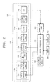
- FIG. 2 is a block diagram illustrating the structure of a geomagnetic sensor according to another exemplary embodiment of the present invention.
- the geomagnetic sensor 200 includes a geomagnetic detection module 210, a tilt detection module 220, a central processing unit 230, a memory 240, a display 250 and a normalizing part 260.
- the geomagnetic detection module 210 operates to output an electric signal corresponding to the geomagnetism.
- the geomagnetic detection module 210 includes a driving signal generating part 210a, a two-axis fluxgate 213, and a signal processing part 210b.
- the driving signal generating part 210a operates to supply driving signals to the driving coils wound on the X and Y fluxgates 213, respectively.
- the driving signal generating part 210a includes a pulse generating part 211 which generates pulse signal, and a pulse amplifying part 212 which amplifies the generated pulse signal and then inverse-amplifies so as to output pulse waves and inverse pulse waves.
- the two-axis fluxgate 213 includes X and Y-axis fluxgates which are in perpendicular relation with each other, and each fluxgate outputs an electromotive force which is transduced from the magnetism of the driving signal.
- the electromotive force may be adjusted to a predetermined output range of values.
- the signal processing part 210b processes, to therefore convert and output such induced electromotive force of the two-axis fluxgate 213 as digital values.
- the digital values may be adjusted to fit within a certain range of output values.
- the signal processing part 210b includes a chopping circuit part 214 which chops the induced electromotive force by using several switches, a first amplifying part 215 which differentially amplifies the chopped electric signal, a filter 216 which filters the amplified electric signal to a range, a second amplifying part 217 which secondly amplifies the filtered signal, and an A/D converter 218 which converts the secondly-amplified signal into a digital value.
- the electric signal which is converted and output by the signal processing part 210b as values, may exceed the range that can be processed by the central processing unit 230.
- a normalizing process is performed to map the electric signal values from the geomagnetic detection module 210 to a predetermined range.
- the normalizing part 260 performs the normalizing job.
- the normalizing part 260 may perform the normalizing process using the following equation: [ Equation 1 ]
- X f norm ( X f ⁇ X f bias )
- X f sf X f max ⁇ X f min 2
- Y f bias Y f max + Y f min 2
- Y f sf Y f max ⁇ Y f min 2
- Xf and Yf refer to output values from the X and Y-axis fluxgates
- Xf norm and Yf norm refer to the output values from the X and Y-axis fluxgates after the normalizing process
- Alpha ( ⁇ ) is set to be smaller than '1' so that the output values of the X and Y-axis fluxgates can be mapped within the range of ⁇ 1. It is advantageous if ⁇ may be set by using a representative dip angle of a local area where the geomagnetic sensor 200 is currently used. For example, in South Korea where the dip angle is approximately 53°, ⁇ may be set to cos 53° ⁇ 0.6.
- Xf max and Xf min and Yf max and Yf min may be obtained by measuring the output values of the geomagnetic sensor 200, while rotating the geomagnetic sensor 200 several times, and selecting the maximum and minimum of the measured values.
- the tilt detection module 220 computes pitch angle and roll angle by measuring the gravity acceleration speed of the geomagnetic sensor 200, and outputs the tilt angle. To this end, the tilt detection module 220 has a two-axis acceleration sensor which is formed in the same axis direction as the two-axis fluxgate sensor 213.
- FIG. 3 shows X and Y axes, which are the reference for the measurement of the pitch and roll angles.
- the X-axis fluxgate and the X-axis acceleration sensor are installed in the X-axis direction, while the Y-axis fluxgate and the Y-axis acceleration sensor are installed in the Y-axis direction.
- the geomagnetic sensor 200 is rotated with reference to the Y-axis which is the reference directional axis of the Y-axis fluxgate and the Y-axis acceleration sensor, the angle between the reference plane and X-Y plane after rotation becomes the pitch angle.
- the angle between the reference plane and X-Y plane after rotation becomes the roll angle.
- the term 'reference plane' refers to a plane formed by the X and Y axes before the rotation, and it is in parallel relation with the ground surface.
- FIG. 4 shows one example of a tilt detection module to measure pitch and roll angles.
- the tilt detection module includes a two-axis acceleration sensor 221, a tilt normalizing part 222 and a tilt computation part 223.
- the two-axis acceleration sensor 221 includes X and Y-axis acceleration sensors which are in perpendicular relation with each other. According to the sloping degree of the geomagnetic sensor 200, the X and Y-axis acceleration sensors output varying electric signals.
- the tilt normalizing part 222 performs a normalizing process so as to map the electric signals from the two-axis acceleration sensor 221 to a predetermined value.
- the tilt computation part 223 operates to compute pitch and roll angles, using the output values of the two-axis acceleration sensor 212 which are normalized by the tilt normalizing part 222.
- the central processing unit 230 first computes azimuth angle when output values are detected at the geomagnetic detection module 210 and the tilt detection module 220, respectively.
- the output values of the geomagnetic detection module 210 may be used by normalizing with the normalizing part 260.
- an azimuth angle is a three-dimensional space value which can be represented by three axes
- a Z-axis output value which is perpendicular to the plane made by the X and Y axes, is also necessary for the azimuth computation. Accordingly, the central processing unit 230 is first required to compute the normalized output value of the Z-axis fluxgate, before performing the first azimuth computation. The following equations may be used.
- Z f norm ( ⁇ ⁇ X f norm ⁇ sin ⁇ ⁇ Y f norm ⁇ cos ⁇ ⁇ sin ⁇ ) cos ⁇ [ Equation 5 ]
- Z f norm ⁇ ⁇ X f norm ⁇ sin ⁇ ⁇ Y f norm ⁇ cos ⁇ ⁇ sin ⁇ [ Equation 6 ]
- Z f norm ⁇ ⁇ X f norm ⁇ sin ⁇
- Zf norm refers to normalized output value (hereinbelow, Z-axis output value) of an imaginary Z-axis fluxgate
- ⁇ refers to a constant value
- ⁇ refers to pitch angle
- ⁇ refers to roll angle
- Xf norm and Yf norm refer to the normalized output values of the X and Y-axis fluxgates, respectively.
- Equations 4 and 5 set the roll angle to '0°'.
- the roll angle can be regarded as '0°'.
- the central processing unit 230 may use one of these Equations depending on the exemplary embodiment being adopted. It is advantageous to use Equation 6 to compute Z-axis output and thus to minimize the computational requirements.
- Beta ( ⁇ ) of the Equations 4 and 5 denotes a constant value which is adopted to compensate for the influence of dip angle.
- sin ⁇ was computed and reflected in the computation of the Z-axis output in order to take the influence of the dip angle into account.
- This method was not so efficient to measure the dip angle accurately. Because the influence by the dip angle in the horizontal position appears as a fixed constant, and this value varies in constant degrees even in the case of tilting, an adequate constant can be estimated by experimentation. Accordingly, by varying the inclination of the geomagnetic sensor 200 in a regular manner, a manufacturer of the geomagnetic sensor 200 can measure and make a database with detected azimuth angles and the values ⁇ . Such a database may then be stored in the memory 240.
- FIG. 5 shows one example of the database stored in the memory 240.
- values ⁇ are set to correspond to the azimuth angles from 0° to 360°.
- the azimuth angles can be divided into 5° or 10° increments.
- the central processing unit 230 uses the initial ⁇ which is determined in advance.
- the initial ⁇ may be set by using sin ⁇ .
- the central processing unit 230 substitutes the normalized X and Y-axis outputs, the pitch angle, and the roll angle in the following Equation, to thus perform a first computation of the azimuth angle.
- the central processing unit 230 looks up the result of the first computation in a database, such as the one shown in FIG. 5, and therefore reads out a corresponding value ⁇ .
- the central processing unit 230 substitutes the new value ⁇ in one of the Equations 4 to 6, and thus re-computes the Z-axis output.
- the other variables except the value ⁇ are fixed, and are the same as the values used for the first computation. Accordingly, the central processing unit 230 re-computes azimuth angle by substituting the re-computed Z-axis output in the Equation 7. Likewise, the other variables, except for the Z-axis output, are fixed as used in the first computation.
- the central processing unit 230 iterates computations of Z-axis output and azimuth angle a certain number of times. Accordingly, if the number of iterations is set to two times, the central processing unit 230 indicates twice-computed azimuth angle, and if the number of iterations is set to three times, the central processing unit 230 reads out value ⁇ corresponding to the twice-computed azimuth angle from the database and thirdly computes the Z-axis output, thirdly computes azimuth angle, and indicates the result.
- the central processing unit 230 controls the display 250 so that the finalized computation result is displayed on the display screen.
- the display 250 indicates azimuth angle through a liquid crystal display (LCD) panel, a light emitting diode (LED), or other such display device known in the art.
- LCD liquid crystal display
- LED light emitting diode
- the central processing unit 230 updates the initial ⁇ to ⁇ which was previously used. Accordingly, the value ⁇ which was used in the previous azimuth detection process is substituted in the first computation of the Z-axis output. Because a more optimum ⁇ value can be used as the azimuth computation repeats, more accurate azimuth angle can be measured.
- FIG 6 is a flowchart provided for explaining the method of measuring azimuth angle according to an exemplary embodiment of the present invention. Referring to FIG 6, first, an electric signal value corresponding to the geomagnetism is detected at the geomagnetic detection module 210 (S610).
- the normalizing part 260 performs a normalizing process and thus maps into values of a predetermined range (S615).
- the normalizing process can be performed by using the Equation 1.
- the tilt detection module 220 detects pitch and roll angles (S620). In order to detect the pitch and roll angles, the tilt detection module 220 normalizes the outputs from the X and Y-axis acceleration sensors using the Equation 2, and then computes pitch and roll angles using the Equation 3.
- Equation 6 the first computation of the normalized output from the imaginary Z-axis fluxgate is performed using the outputs from the normalized X and Y-axis fluxgates, the pitch angle and the roll angle (S625).
- One of the Equations 4 to 6 may be used in the computation, but it is advantageous if Equation 6 is used in order to reduce computational requirements as much as possible.
- an initial value is used as for the value ⁇ in the Z-axis output computation.
- the initial value can be obtained from the sin-function of the dip angle of the local area, and for example, approximately 0.8 can be used as the initial value ⁇ in South Korea.
- the first azimuth computation is performed using the computed Z-axis output (S630).
- the Equation 7 can be used for the azimuth angle computation.
- the central processing unit 230 substitutes the resultant azimuth angle of the first computation in the stored database and thus reads out corresponding value ⁇ (S635).
- a manufacturer of the geomagnetic sensor 200 builds a database of optimum values ⁇ for each of the azimuth angles and stores the database in the memory 240.
- the central processing unit 230 secondly computes the Z-axis output by using the read value ⁇ (S640). In this case, other variables except for the value ⁇ are fixed.
- the second azimuth computation is performed using the secondly-computed Z-axis output (S645). Likewise, the other variables except for the Z-axis output, are fixed.
- the number of iterations of the azimuth computations have been met, as determined by the manufacturer or the user (S650), and if so, the final result of the computations is indicated on the display screen (S655). For example, if the number of computation iterations is set to three times, the value ⁇ corresponding to the secondly-computed azimuth angle is read out from the memory 240 (S635), and the Z-axis output and the azimuth angle are computed a third time (S640, S645).
- the central processing unit 230 updates the initial value ⁇ to the last-used value ⁇ (S665). Accordingly, in the first computation of the Z-axis output using the next outputs from the geomagnetic detection module 210 and the tilt detection module 220, the updated value ⁇ is used as the initial value. As the azimuth measurement repeats, a more accurate value of the constant ⁇ can be used, and therefore, a more accurate azimuth can be obtained.
- an accurate azimuth angle can be computed in consideration of the influence by the dip angle. Therefore, a similar effect as using the three-axis fluxgate can be obtained from the two-axis fluxgate sensor, and a high quality and ultra compact geomagnetic sensor can be provided.
Landscapes
- Engineering & Computer Science (AREA)
- Radar, Positioning & Navigation (AREA)
- Remote Sensing (AREA)
- Physics & Mathematics (AREA)
- General Physics & Mathematics (AREA)
- Life Sciences & Earth Sciences (AREA)
- Environmental & Geological Engineering (AREA)
- General Life Sciences & Earth Sciences (AREA)
- Geology (AREA)
- Electromagnetism (AREA)
- Measuring Magnetic Variables (AREA)
- Navigation (AREA)
Applications Claiming Priority (1)
| Application Number | Priority Date | Filing Date | Title |
|---|---|---|---|
| KR1020040104770A KR100620957B1 (ko) | 2004-12-13 | 2004-12-13 | 방위각을 측정하는 지자기센서 및 그 방법 |
Publications (1)
| Publication Number | Publication Date |
|---|---|
| EP1669718A1 true EP1669718A1 (de) | 2006-06-14 |
Family
ID=36062882
Family Applications (1)
| Application Number | Title | Priority Date | Filing Date |
|---|---|---|---|
| EP05257578A Withdrawn EP1669718A1 (de) | 2004-12-13 | 2005-12-09 | Geomagnetischer Sensor zur Detektion eines Azimuthwinkels und Verfahren dafür |
Country Status (4)
| Country | Link |
|---|---|
| US (1) | US7200948B2 (de) |
| EP (1) | EP1669718A1 (de) |
| JP (1) | JP2006170997A (de) |
| KR (1) | KR100620957B1 (de) |
Cited By (2)
| Publication number | Priority date | Publication date | Assignee | Title |
|---|---|---|---|---|
| EP3926298A1 (de) | 2020-06-17 | 2021-12-22 | ETA SA Manufacture Horlogère Suisse | Navigationsinstrument mit neigungskompensation und entsprechende methode |
| CN119572213A (zh) * | 2025-02-08 | 2025-03-07 | 青岛智腾微电子有限公司 | 基于高精度磁通门传感器的井斜与地磁场强度测量系统 |
Families Citing this family (11)
| Publication number | Priority date | Publication date | Assignee | Title |
|---|---|---|---|---|
| KR100594971B1 (ko) * | 2004-01-09 | 2006-06-30 | 삼성전자주식회사 | 지자기 센서를 이용한 입력장치 및 이를 이용한 입력신호생성방법 |
| JP4176040B2 (ja) * | 2004-03-31 | 2008-11-05 | 京セラ株式会社 | 携帯通信端末とその地磁気センサの誤差補正方法 |
| CH697492B1 (de) * | 2004-04-17 | 2008-11-14 | Vectronix Ag | Verfahren zum Schätzen der Genauigkeit azimutaler Ausrichtungen, Verfahren zum Bereitstellen einer azimutalen Ausrichtung eines tragbaren Zielgeräts und eines geschätzten Wertes deren Genauigkeit und tragbares Zielgerät. |
| US20070006472A1 (en) * | 2005-05-16 | 2007-01-11 | Aaron Bauch | Independent personal underwater navigation system for scuba divers |
| CN1892179A (zh) * | 2005-07-01 | 2007-01-10 | 雅马哈株式会社 | 用于检测方位角和倾角的设备和方法、程序、及便携式终端装置 |
| KR100799536B1 (ko) * | 2005-11-08 | 2008-01-31 | 한국전자통신연구원 | 2축 지자계 센서의 경사각 오차를 보상하기 위한 가상축 지자계 데이터 추정 장치 및 그 방법과, 그를 이용한 방위각 산출 시스템 |
| KR100655937B1 (ko) * | 2005-11-25 | 2006-12-11 | 삼성전자주식회사 | 방위각을 산출하는 지자기 센서 및 그 방법 |
| JP5299054B2 (ja) * | 2009-04-21 | 2013-09-25 | ソニー株式会社 | 電子機器、表示制御方法およびプログラム |
| DE102009057258A1 (de) * | 2009-12-08 | 2011-06-09 | Embex Gmbh | Magnetfeldsensor und Verfahren zur Messung der horizontalen Komponente eines Magnetfelds |
| EP2578992B1 (de) * | 2011-10-06 | 2017-01-25 | Vectronix AG | Geographisch nordreferenzierte Azimutbestimmung |
| JP6215277B2 (ja) * | 2015-09-07 | 2017-10-18 | 京セラ株式会社 | 携帯機器、制御方法及び制御プログラム |
Citations (4)
| Publication number | Priority date | Publication date | Assignee | Title |
|---|---|---|---|---|
| US4725957A (en) * | 1984-06-16 | 1988-02-16 | Robert Bosch Gmbh | Process for correcting angle errors in an electronic compass in vehicles |
| US4995165A (en) * | 1987-04-14 | 1991-02-26 | The Secretary Of State For Defence In Her Britannic Majesty's Government Of The United Kingdom Of Great Britain And Northern Ireland | Roll-independent magneto meter system |
| DE3937160A1 (de) * | 1989-11-08 | 1991-05-16 | Bosch Gmbh Robert | Elektronischer kompass mit neigungswinkelkorrektur |
| EP1553384A2 (de) * | 2003-12-30 | 2005-07-13 | Samsung Electronics Co., Ltd. | Geomagnetischer Sensor mit Azimutkalibirierung durch Neigungskompensation und zugehöriges Verfahren |
Family Cites Families (13)
| Publication number | Priority date | Publication date | Assignee | Title |
|---|---|---|---|---|
| JPS5985910A (ja) | 1982-11-09 | 1984-05-18 | Nippon Telegr & Teleph Corp <Ntt> | 磁界ベクトル検出方式 |
| JPH07119612B2 (ja) * | 1989-01-13 | 1995-12-20 | 日産自動車株式会社 | 車両用走行方位検出装置 |
| US5345382A (en) * | 1992-05-15 | 1994-09-06 | Zexel Corporation | Calibration method for a relative heading sensor |
| JP3008813B2 (ja) * | 1995-04-07 | 2000-02-14 | ソニー株式会社 | 方位出力装置 |
| JPH1123298A (ja) | 1997-07-01 | 1999-01-29 | Unisia Jecs Corp | 車両の変位角計測装置 |
| JP4026937B2 (ja) | 1998-06-29 | 2007-12-26 | 古野電気株式会社 | 電子磁気コンパス |
| KR100533106B1 (ko) * | 2002-08-06 | 2005-12-05 | 삼성전자주식회사 | 지자계 센서의 자세 오차 보상장치 및 방법 |
| US6860023B2 (en) * | 2002-12-30 | 2005-03-01 | Honeywell International Inc. | Methods and apparatus for automatic magnetic compensation |
| JP4381162B2 (ja) * | 2003-03-27 | 2009-12-09 | シチズンホールディングス株式会社 | 方位測定装置、方位測定方法、および方位測定プログラム |
| KR100555656B1 (ko) * | 2003-08-27 | 2006-03-03 | 삼성전자주식회사 | 복각 검출 기능을 지원하는 지자기 센서 및 그 검출 방법 |
| KR100568285B1 (ko) * | 2003-12-13 | 2006-04-05 | 삼성전기주식회사 | 틸트 보상형 전자 나침반의 복각 탐색 방법 |
| KR100594971B1 (ko) * | 2004-01-09 | 2006-06-30 | 삼성전자주식회사 | 지자기 센서를 이용한 입력장치 및 이를 이용한 입력신호생성방법 |
| KR100574506B1 (ko) * | 2004-02-26 | 2006-04-27 | 삼성전자주식회사 | 연산된 방위각의 오류여부를 표시하는 지자기센서 및 그방위각측정방법 |
-
2004
- 2004-12-13 KR KR1020040104770A patent/KR100620957B1/ko not_active Expired - Fee Related
-
2005
- 2005-12-08 US US11/296,345 patent/US7200948B2/en not_active Expired - Fee Related
- 2005-12-09 EP EP05257578A patent/EP1669718A1/de not_active Withdrawn
- 2005-12-13 JP JP2005359610A patent/JP2006170997A/ja not_active Ceased
Patent Citations (4)
| Publication number | Priority date | Publication date | Assignee | Title |
|---|---|---|---|---|
| US4725957A (en) * | 1984-06-16 | 1988-02-16 | Robert Bosch Gmbh | Process for correcting angle errors in an electronic compass in vehicles |
| US4995165A (en) * | 1987-04-14 | 1991-02-26 | The Secretary Of State For Defence In Her Britannic Majesty's Government Of The United Kingdom Of Great Britain And Northern Ireland | Roll-independent magneto meter system |
| DE3937160A1 (de) * | 1989-11-08 | 1991-05-16 | Bosch Gmbh Robert | Elektronischer kompass mit neigungswinkelkorrektur |
| EP1553384A2 (de) * | 2003-12-30 | 2005-07-13 | Samsung Electronics Co., Ltd. | Geomagnetischer Sensor mit Azimutkalibirierung durch Neigungskompensation und zugehöriges Verfahren |
Cited By (4)
| Publication number | Priority date | Publication date | Assignee | Title |
|---|---|---|---|---|
| EP3926298A1 (de) | 2020-06-17 | 2021-12-22 | ETA SA Manufacture Horlogère Suisse | Navigationsinstrument mit neigungskompensation und entsprechende methode |
| US20210397133A1 (en) * | 2020-06-17 | 2021-12-23 | Eta Sa Manufacture Horlogère Suisse | Navigation instrument with tilt compensation and associated method |
| US12241742B2 (en) * | 2020-06-17 | 2025-03-04 | Eta Sa Manufacture Horlogère Suisse | Navigation instrument with tilt compensation and associated method |
| CN119572213A (zh) * | 2025-02-08 | 2025-03-07 | 青岛智腾微电子有限公司 | 基于高精度磁通门传感器的井斜与地磁场强度测量系统 |
Also Published As
| Publication number | Publication date |
|---|---|
| KR20060066239A (ko) | 2006-06-16 |
| JP2006170997A (ja) | 2006-06-29 |
| US20060123642A1 (en) | 2006-06-15 |
| US7200948B2 (en) | 2007-04-10 |
| KR100620957B1 (ko) | 2006-09-19 |
Similar Documents
| Publication | Publication Date | Title |
|---|---|---|
| US6536123B2 (en) | Three-axis magnetic sensor, an omnidirectional magnetic sensor and an azimuth measuring method using the same | |
| US6836971B1 (en) | System for using a 2-axis magnetic sensor for a 3-axis compass solution | |
| KR100894171B1 (ko) | 3축 자기 센서 및 전방위 자기 센서 | |
| EP1388727B1 (de) | Vorrichtung und Verfahren zur Azimutwinkelberechnung | |
| US7486323B2 (en) | Portable electronic device for changing menu display state according to rotating degree and method thereof | |
| EP1519148B1 (de) | Azimuthmesseinrichtung und azimuthmessverfahren | |
| US7826999B1 (en) | Magnetic tilt compensated heading compass with adaptive zoffset | |
| EP1669718A1 (de) | Geomagnetischer Sensor zur Detektion eines Azimuthwinkels und Verfahren dafür | |
| EP1553384B1 (de) | Geomagnetischer Sensor mit Azimutkalibirierung durch Neigungskompensation und zugehöriges Verfahren | |
| US7168176B2 (en) | Geomagnetic sensor for informing users whether detected azimuth angle is acceptable, and a method thereof | |
| US20070250262A1 (en) | Device, method and medium detecting errors generated by distortion in a magnetic field | |
| US7162807B2 (en) | Geomagnetic sensor having a dip angle detection function and dip angle detection method therefor | |
| KR100571795B1 (ko) | 복각 검출 기능을 지원하는 지자기 센서 및 그 방법 | |
| KR100568285B1 (ko) | 틸트 보상형 전자 나침반의 복각 탐색 방법 | |
| KR100655936B1 (ko) | 방위각 측정 장치 및 방법 | |
| JPH0772689B2 (ja) | 方位標定装置 | |
| JP2002168629A (ja) | 携帯端末機器用磁気方位検出装置の取り付け方法 | |
| JP2002158750A (ja) | 携帯端末機器用姿勢角度検出装置および携帯端末機器用磁気方位検出装置 |
Legal Events
| Date | Code | Title | Description |
|---|---|---|---|
| PUAI | Public reference made under article 153(3) epc to a published international application that has entered the european phase |
Free format text: ORIGINAL CODE: 0009012 |
|
| AK | Designated contracting states |
Kind code of ref document: A1 Designated state(s): AT BE BG CH CY CZ DE DK EE ES FI FR GB GR HU IE IS IT LI LT LU LV MC NL PL PT RO SE SI SK TR |
|
| AX | Request for extension of the european patent |
Extension state: AL BA HR MK YU |
|
| 17P | Request for examination filed |
Effective date: 20060726 |
|
| AKX | Designation fees paid |
Designated state(s): DE FR GB |
|
| 17Q | First examination report despatched |
Effective date: 20070709 |
|
| STAA | Information on the status of an ep patent application or granted ep patent |
Free format text: STATUS: THE APPLICATION IS DEEMED TO BE WITHDRAWN |
|
| 18D | Application deemed to be withdrawn |
Effective date: 20100701 |