EP1670013A2 - Elektrisches Schaltgerät, bei welchem Gehäuse und Auslöse-Schaltung eine zusammengesetzte Einheit bilden - Google Patents
Elektrisches Schaltgerät, bei welchem Gehäuse und Auslöse-Schaltung eine zusammengesetzte Einheit bilden Download PDFInfo
- Publication number
- EP1670013A2 EP1670013A2 EP05026827A EP05026827A EP1670013A2 EP 1670013 A2 EP1670013 A2 EP 1670013A2 EP 05026827 A EP05026827 A EP 05026827A EP 05026827 A EP05026827 A EP 05026827A EP 1670013 A2 EP1670013 A2 EP 1670013A2
- Authority
- EP
- European Patent Office
- Prior art keywords
- printed circuit
- housing
- operating mechanism
- separable contacts
- circuit board
- Prior art date
- Legal status (The legal status is an assumption and is not a legal conclusion. Google has not performed a legal analysis and makes no representation as to the accuracy of the status listed.)
- Granted
Links
Images


Classifications
-
- H—ELECTRICITY
- H01—ELECTRIC ELEMENTS
- H01H—ELECTRIC SWITCHES; RELAYS; SELECTORS; EMERGENCY PROTECTIVE DEVICES
- H01H71/00—Details of the protective switches or relays covered by groups H01H73/00 - H01H83/00
- H01H71/10—Operating or release mechanisms
- H01H71/12—Automatic release mechanisms with or without manual release
- H01H71/123—Automatic release mechanisms with or without manual release using a solid-state trip unit
-
- H—ELECTRICITY
- H01—ELECTRIC ELEMENTS
- H01H—ELECTRIC SWITCHES; RELAYS; SELECTORS; EMERGENCY PROTECTIVE DEVICES
- H01H71/00—Details of the protective switches or relays covered by groups H01H73/00 - H01H83/00
- H01H71/02—Housings; Casings; Bases; Mountings
- H01H71/0264—Mountings or coverplates for complete assembled circuit breakers, e.g. snap mounting in panel
- H01H71/0271—Mounting several complete assembled circuit breakers together
- H01H2071/0278—Mounting several complete assembled circuit breakers together with at least one of juxtaposed casings dedicated to an auxiliary device, e.g. for undervoltage or shunt trip
-
- H—ELECTRICITY
- H01—ELECTRIC ELEMENTS
- H01H—ELECTRIC SWITCHES; RELAYS; SELECTORS; EMERGENCY PROTECTIVE DEVICES
- H01H71/00—Details of the protective switches or relays covered by groups H01H73/00 - H01H83/00
- H01H71/10—Operating or release mechanisms
- H01H71/12—Automatic release mechanisms with or without manual release
- H01H71/123—Automatic release mechanisms with or without manual release using a solid-state trip unit
- H01H2071/124—Automatic release mechanisms with or without manual release using a solid-state trip unit with a hybrid structure, the solid state trip device being combined with a thermal or a electromagnetic trip
-
- H—ELECTRICITY
- H01—ELECTRIC ELEMENTS
- H01H—ELECTRIC SWITCHES; RELAYS; SELECTORS; EMERGENCY PROTECTIVE DEVICES
- H01H83/00—Protective switches, e.g. circuit-breaking switches, or protective relays operated by abnormal electrical conditions otherwise than solely by excess current
- H01H83/20—Protective switches, e.g. circuit-breaking switches, or protective relays operated by abnormal electrical conditions otherwise than solely by excess current operated by excess current as well as by some other abnormal electrical condition
- H01H2083/201—Protective switches, e.g. circuit-breaking switches, or protective relays operated by abnormal electrical conditions otherwise than solely by excess current operated by excess current as well as by some other abnormal electrical condition the other abnormal electrical condition being an arc fault
-
- H—ELECTRICITY
- H01—ELECTRIC ELEMENTS
- H01H—ELECTRIC SWITCHES; RELAYS; SELECTORS; EMERGENCY PROTECTIVE DEVICES
- H01H71/00—Details of the protective switches or relays covered by groups H01H73/00 - H01H83/00
- H01H71/02—Housings; Casings; Bases; Mountings
- H01H71/0264—Mountings or coverplates for complete assembled circuit breakers, e.g. snap mounting in panel
- H01H71/0271—Mounting several complete assembled circuit breakers together
Definitions
- This invention relates to electrical switching apparatus and, more particularly, to circuit interrupters, such as, for example, aircraft or aerospace circuit breakers providing arc fault protection.
- Circuit breakers are used to protect electrical circuitry from damage due to an overcurrent condition, such as an overload condition or a relatively high level short circuit or fault condition.
- an overcurrent condition such as an overload condition or a relatively high level short circuit or fault condition.
- small circuit breakers commonly referred to as miniature circuit breakers, used for residential and light commercial applications, such protection is typically provided by a thermal-magnetic trip device.
- This trip device includes a bimetal, which heats and bends in response to a persistent overcurrent condition. The bimetal, in turn, unlatches a spring powered operating mechanism, which opens the separable contacts of the circuit breaker to interrupt current flow in the protected power system.
- subminiature circuit breakers have provided protection against persistent overcurrents implemented by a latch triggered by a bimetal responsive to I 2 R heating resulting from the overcurrent.
- I 2 R heating resulting from the overcurrent.
- a housing and a trip circuit cooperate to form a composite structure which comprises at least one printed circuit board and an over-molding material disposed thereon.
- the invention employs molded housing halves that electrically and thermally insulate arc fault detection (AFD) electronics from a current carrying operating mechanism.
- the AFD electronics are over-molded to the molded housing halves using an over-molding material, such as, for example, a thermally conductive epoxy coating. Over-molding the AFD electronics to the molded housing halves eliminates the additional space required to package such electronics while providing superior strength, dielectric isolation and thermal heat transfer surface area.
- an electrical switching apparatus comprises: a housing; separable contacts; an operating mechanism adapted to open and close the separable contacts; and a trip circuit cooperating with the operating mechanism to trip open the separable contacts, wherein the housing and the trip circuit cooperate to form a composite structure which comprises at least one printed circuit board and an over-molding material disposed thereon.
- the housing may include a first housing portion and a second housing portion cooperating with the first housing portion to house the separable contacts and the operating mechanism therein.
- a circuit breaker comprises: a housing; separable contacts; an operating mechanism adapted to open and close the separable contacts; and a trip circuit cooperating with the operating mechanism to trip open the separable contacts, wherein the housing and the trip circuit cooperate to form an external composite structure which comprises at least one printed circuit board and an over-molding material disposed thereon.
- the trip circuit may include the at least one printed circuit board.
- the first and second housing portions may form a first surface disposed toward the separable contacts and the operating mechanism and a second surface opposite from the first surface.
- the at least one printed circuit board may be coupled to the second surface.
- the housing may further include the over-molding material coupling the at least one printed circuit board to the second surface.
- the over-molding material may be a thermally conductive encapsulating material, such as thermally conductive epoxy coating.
- composite means a generally solid material which comprises two or more substances and/or structures (e.g., without limitation, one or more printed circuit boards; an over-molding material) having different physical characteristics and in which each of such substances and/or structures retains its identity while contributing desirable properties to the whole.
- substances and/or structures e.g., without limitation, one or more printed circuit boards; an over-molding material
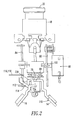
- a circuit breaker 10 comprises an enclosure 12 having a pair of terminals 14 and 16 thereon which extend exteriorly of the enclosure 12 for electrical connection to an electrical source and load, respectively.
- a threaded, conductive ferrule 18 extends exteriorly of the enclosure 12 for the guidance of a manual operator 20 of a plunger assembly 21.
- the ferrule 18, in conjunction with a nut (not shown), provides a mounting and electrically conductive connection mechanism for the circuit breaker 10 on a panelboard (not shown).
- the manual operator 20 is provided with a trip indicator 22.
- the manual operator 20 and trip indicator 22 are capable of sliding axial movement with respect to the ferrule 18.
- the manual operator 20 is provided with a central portion 24 having a central slot 26 extending approximately half the length thereof.
- a clevis or thermal latch element 36 is provided with a latch surface 38 and a depending portion 40.
- the clevis 36 is pivotally supported by a pin 42 which is movable relative to the manual operator 20 in a slot (not shown).
- the end portions of the pin 42 are retained within grooves (not shown) in the central housing 12 which guide axial movement thereof.
- the mechanical latch elements 46 have camming apertures 51 (only one aperture 51 is shown) therein defining camming surfaces 52 (only one camming surface 52 is shown) which are disposed at an acute angle with respect to the axis of reciprocation of the manual operator 20 thereby to effect manual opening of the circuit breaker 10.
- Two lower camming surfaces 54 (only one camming surface 54 is shown) are disposed at substantially a right angle with respect to the axis of reciprocation of the manual operator 20 to provide positive locking of the circuit breaker 10.
- the central stem portion 24 carries a camming pin 56 which extends across the slot 26 therein and through the camming apertures 51 of the mechanical latch elements 46, in order to be in operative engagement therewith.
- a spring 62 is provided to resiliently bias the manual operator 20, clevis 36 and latch elements 46 upwardly with respect to the ferrule 18.
- a movable contact carrier or plunger 64 of a contact plunger assembly 65 has a central opening 66 therein for acceptance of the clevis 36.
- the contact carrier 64 carries a contact bridge 68 (shown in Figure 2) having a pair of movable contacts 70 (only one contact 70 is shown in Figure 2) positioned thereon.
- the movable contacts 70 are engageable with fixed contacts 72 ( Figure 2) to complete a circuit from terminal 14 to terminal 16 through a current responsive bimetal 84 of the circuit breaker 10, as will be described.
- a helical coil plunger return spring 74 abuts against a spring retainer portion 75 of the housing 12 at one end and the movable contact carrier 64 at its other end, in order to normally bias the contact carrier 64 upwardly relative to the housing 12.
- a clevis guide assembly (e.g., made of ceramic) 86 couples the overload slide 80 to and insulates it from the bimetal 84.
- the overload slide 80 is provided with a slot 88 which accepts and closely cooperates with the clevis 36 to effect pivoting thereof in response to lateral movement of the slide 80.
- the ambient temperature slide 82 underlies the overload slide 80 and is movable internally of the contact carrier 64 under the influence of an elongated ambient temperature compensating bimetal 90, which is part of an ambient compensator assembly 92 including an adjustable screw guide 93, a calibrate screw 94 and a compensator spring 95.
- the ambient temperature compensating bimetal 90 is interlocked to the ambient temperature slide 82, whereby lateral movement of such slide 82 is controlled, in part, by such bimetal 90.
- the ambient temperature slide 82 is provided with a slot 96, which, when the circuit breaker 10 is in the contacts closed position, as shown, accepts the hooked end 40 of the clevis 36. In the contacts closed position, the latch surface 38 of the clevis 36 engages the upper surface of the ambient temperature slide 82 adjacent the periphery of the slot 96 with a pressure determined by the upward resilient bias provided by spring 74.
- a miniature coil assembly 98 includes a coil 100 controlled by AFD PCB2 120 ( Figure 7) and a plunger 102.
- the plunger 102 is coupled to the ambient temperature slide 82, in order to effect an arc fault trip function therewith.
- Figure 2 shows the current path through the circuit breaker 10 of Figure 1.
- the current path is established by a contact assembly 110 including the line terminal 14 and a first fixed contact 72A, the first movable contact 70 to the contact bridge 68 to the second movable contact 70 (not shown), the second movable contact 70 to a second fixed contact 72B, the second fixed contact 72B to a first leg (not shown) of the bimetal 84 by a first flexible conductor 112, through the bimetal 84 to a second leg (not shown) thereof to a second flexible conductor 114, and to the load terminal 16.
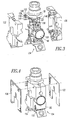
- the internal mechanism including, for example, the operating mechanism 134
- the PCBs 120,122 are coupled to the respective case halves 132,130 by employing the screws 146,148 and the nuts 150,152 as shown in Figure 5.
- all electrical connections such as, for example, solder, pin and wire connections, are made prior to over-molding.
- a suitable gap filler (not shown) is employed to prevent the over-molding material from entering the internal operating mechanism 134.
- the assembled device is inserted into suitable mold tooling (not shown) using the screws 146,148 and rivet 154 for proper location and orientation.
- suitable over-molding material is injected into the mold tooling.
- the case halves 130,132 and PCBs 120,122 are inserted into a suitable mold tooling (not shown) as individual entities. Locating holes on the case halves 130,132 and PCBs 120,122 are employed for location within the mold tooling.
- over-molding material is injected into the mold tooling. Vacuum assist or pressurized injection methods may be employed. The over-molding material fills all open voids, thus, encapsulating the PCBs 120,122 and providing a method of joining and sealing the PCBs 120,122 to the respective case halves 132,130. This method also employs via/holes thru the PCBs 120,122 to assist in mechanical coupling.
- the internal operating mechanism 134 is built into the sub-assembly formed by the PCBs 120,122 and case halves 130,132. Then, all solder, pin and wire electrical connections are made. Finally, a secondary cover (not shown) is applied to protect the side opening ( Figure 13).
- Figure 6 shows the assembled circuit breaker 10 with the AFD electronics 120,122 ( Figure 5) being chemically and mechanically linked to the base structure of the respective housing halves 132,130, thereby providing an overall compact and robust electro/mechanical package.
- Figures 7 and 8 show the two AFD printed circuit board assemblies 120 and 122, respectively, of Figure 4.
- the neutral (or, more accurately, the aircraft frame from the bezel 18 of Figure 1) is electrically connected by the two screws 146,148 ( Figure 3) to both of the PCBs 120,122 at pads E5,E6,E7,E8.
- the PCBs 120,122 derive power from voltage between the neutral or frame at pads E5,E6,E7,E8 ( Figures 7 and 8) and the local ground, which is the same potential as the load terminal 16 ( Figure 1).
- the composite structure formed by bonding the AFD printed circuit boards 120,122 (e.g., made of FR4; glass base epoxy binder) and the over-molding material 156 (e.g., made of thermally conductive epoxy coating; a suitable over-molding compound; a suitable potting material) provides improvements in thermal conductivity of the heat of the AFD electronics to the surrounding air through the thermally conductive epoxy coating.
- Over-molding the two AFD printed circuit boards 120,122 to the molded housing halves 130,132 also eliminates the additional space required to package the AFD electronics while providing superior strength, dielectric isolation and thermal heat transfer surface area.
- the housing halves 130,132 provide thermal isolation of the AFD electronics 120,122 from the internal operating mechanism 134 ( Figure 2), such as, for example, in particular, the bimetal 84 and the associated electrical power conductors.
- a suitable trip circuit may implement, for example, the AFD electronics 120,122 in a combination of one or more of analog, digital and/or processor-based circuits, and/or in combination with one or more printed circuit boards (PCBs).
- PCBs printed circuit boards
- an example operating mechanism 134 is disclosed, a wide range of suitable operating mechanisms for electrical switching apparatus may be employed.
Landscapes
- Breakers (AREA)
- Switch Cases, Indication, And Locking (AREA)
Applications Claiming Priority (1)
| Application Number | Priority Date | Filing Date | Title |
|---|---|---|---|
| US11/008,463 US7170376B2 (en) | 2004-12-09 | 2004-12-09 | Electrical switching apparatus including a housing and a trip circuit forming a composite structure |
Publications (3)
| Publication Number | Publication Date |
|---|---|
| EP1670013A2 true EP1670013A2 (de) | 2006-06-14 |
| EP1670013A3 EP1670013A3 (de) | 2007-08-22 |
| EP1670013B1 EP1670013B1 (de) | 2009-09-23 |
Family
ID=35954892
Family Applications (1)
| Application Number | Title | Priority Date | Filing Date |
|---|---|---|---|
| EP05026827A Expired - Lifetime EP1670013B1 (de) | 2004-12-09 | 2005-12-08 | Elektrisches Schaltgerät, bei welchem Gehäuse und Auslöse-Schaltung eine zusammengesetzte Einheit bilden |
Country Status (3)
| Country | Link |
|---|---|
| US (1) | US7170376B2 (de) |
| EP (1) | EP1670013B1 (de) |
| DE (1) | DE602005016766D1 (de) |
Cited By (3)
| Publication number | Priority date | Publication date | Assignee | Title |
|---|---|---|---|---|
| WO2009153644A1 (en) * | 2008-06-16 | 2009-12-23 | Eaton Corporation | Method of electrically grounding an electrical switching apparatus and electrical switching apparatus including the same |
| WO2012080828A3 (en) * | 2010-12-17 | 2012-11-15 | Eaton Corporation | Electrical system, and circuit protection module and electrical switching apparatus therefor |
| CN103996575A (zh) * | 2014-05-09 | 2014-08-20 | 安庆天瑞新材料科技股份有限公司 | 一种具有电流检测及通讯功能的热磁式断路器 |
Families Citing this family (16)
| Publication number | Priority date | Publication date | Assignee | Title |
|---|---|---|---|---|
| US7518475B2 (en) * | 2007-07-24 | 2009-04-14 | Eaton Corporation | Electrical switching apparatus, circuit interrupter and method of interrupting overcurrents of a power circuit |
| US7570146B2 (en) * | 2007-07-25 | 2009-08-04 | Eaton Corporation | Circuit breaker including ambient compensation bimetal holding and releasing arc fault indicator |
| US7576471B1 (en) * | 2007-09-28 | 2009-08-18 | Triquint Semiconductor, Inc. | SAW filter operable in a piston mode |
| US8971055B2 (en) * | 2008-12-16 | 2015-03-03 | Schneider Electric USA, Inc. | Residential circuit breaker with flexible printed circuit boards |
| US7994882B2 (en) * | 2009-04-18 | 2011-08-09 | General Electric Company | Space allocation within a circuit breaker |
| US8138864B2 (en) * | 2009-06-01 | 2012-03-20 | Eaton Corporation | Circuit interrupter including a molded case made of liquid crystal polymer |
| US8514552B2 (en) | 2010-12-17 | 2013-08-20 | Eaton Corporation | Electrical system and matrix assembly therefor |
| BR112013031432B1 (pt) * | 2011-06-21 | 2021-03-02 | Eaton Corporation | painel de disjuntor de encaixe selado |
| BR112013031733B1 (pt) * | 2011-06-27 | 2021-10-26 | Eaton Corporation | Módulo de disjuntor e método para aterrar eletricamente um disjuntor em um painel |
| DE102013008128A1 (de) * | 2012-05-15 | 2013-11-21 | Marquardt Mechatronik Gmbh | Elektrischer Schalter |
| WO2015047820A1 (en) * | 2013-09-26 | 2015-04-02 | Labinal, Llc | Circuit breaker module with plug-in circuit breakers |
| WO2015084768A1 (en) | 2013-12-03 | 2015-06-11 | Labinal, Llc | Electrical switching apparatus including a remotely controllable actuator structured to move a push/pull operating handle |
| KR101869724B1 (ko) * | 2017-01-05 | 2018-06-21 | 엘에스산전 주식회사 | 회로차단기의 전자 트립 장치 |
| KR102299858B1 (ko) * | 2017-03-15 | 2021-09-08 | 엘에스일렉트릭 (주) | 회로차단기의 전자 트립 장치 |
| WO2018217883A2 (en) | 2017-05-23 | 2018-11-29 | Pass & Seymour, Inc. | Arc fault circuit interrupter |
| US10468219B2 (en) * | 2017-09-07 | 2019-11-05 | Carling Technologies, Inc. | Circuit interrupter with status indication |
Family Cites Families (22)
| Publication number | Priority date | Publication date | Assignee | Title |
|---|---|---|---|---|
| US4092623A (en) | 1976-07-21 | 1978-05-30 | Mechanical Products | Circuit breaker |
| US4110719A (en) | 1977-04-11 | 1978-08-29 | Mechanical Products | Three phase circuit breaker |
| US4415875A (en) | 1982-05-18 | 1983-11-15 | Mechanical Products, Inc. | Circuit breaker |
| US4568899A (en) * | 1984-03-27 | 1986-02-04 | Siemens Aktiengesellschaft | Ground fault accessory for a molded case circuit breaker |
| US4667263A (en) * | 1985-04-22 | 1987-05-19 | General Electric Company | Ground fault module for ground fault circuit breaker |
| US4652975A (en) * | 1986-04-28 | 1987-03-24 | General Electric Company | Mounting arrangement for circuit breaker current sensing transformers |
| US4725799A (en) * | 1986-09-30 | 1988-02-16 | Westinghouse Electric Corp. | Circuit breaker with remote control |
| JP2925402B2 (ja) * | 1991-09-11 | 1999-07-28 | 三菱電機株式会社 | 高熱伝導性低収縮湿式不飽和ポリエステル系樹脂組成物を成形してなる筐体を有する回路遮断器 |
| US5224006A (en) | 1991-09-26 | 1993-06-29 | Westinghouse Electric Corp. | Electronic circuit breaker with protection against sputtering arc faults and ground faults |
| US5691869A (en) | 1995-06-06 | 1997-11-25 | Eaton Corporation | Low cost apparatus for detecting arcing faults and circuit breaker incorporating same |
| US6522509B1 (en) | 2000-07-21 | 2003-02-18 | Eaton Corporation | Arc fault detection in ac electric power systems |
| US6633222B2 (en) * | 2000-08-08 | 2003-10-14 | Furukawa Precision Engineering Co., Ltd. | Battery breaker |
| US6307749B1 (en) * | 2000-10-23 | 2001-10-23 | Delphi Technologies, Inc. | Overmolded electronic module with underfilled surface-mount components |
| US6542056B2 (en) | 2001-04-30 | 2003-04-01 | Eaton Corporation | Circuit breaker having a movable and illuminable arc fault indicator |
| US6710688B2 (en) | 2001-04-30 | 2004-03-23 | Eaton Corporation | Circuit breaker |
| US6522228B2 (en) * | 2001-04-30 | 2003-02-18 | Eaton Corporation | Circuit breaker including an arc fault trip actuator having an indicator latch and a trip latch |
| US6842325B2 (en) * | 2001-09-19 | 2005-01-11 | Square D Company | Flexible circuit adhered to metal frame of device |
| US6538862B1 (en) * | 2001-11-26 | 2003-03-25 | General Electric Company | Circuit breaker with a single test button mechanism |
| US6545574B1 (en) * | 2001-12-17 | 2003-04-08 | General Electric Company | Arc fault circuit breaker |
| US6700138B2 (en) * | 2002-02-25 | 2004-03-02 | Silicon Bandwidth, Inc. | Modular semiconductor die package and method of manufacturing thereof |
| ES2294279T3 (es) * | 2002-03-08 | 2008-04-01 | Kearney-National, Inc. | Rele moldeado de montaje superficial y el metodo de fabricacion del mismo. |
| US7038337B2 (en) * | 2003-05-20 | 2006-05-02 | Siemens Vdo Automotive Corporation | EMI suppression in permanent magnet DC motors having PCB outside motor in connector and overmolded |
-
2004
- 2004-12-09 US US11/008,463 patent/US7170376B2/en not_active Expired - Lifetime
-
2005
- 2005-12-08 EP EP05026827A patent/EP1670013B1/de not_active Expired - Lifetime
- 2005-12-08 DE DE602005016766T patent/DE602005016766D1/de not_active Expired - Lifetime
Cited By (6)
| Publication number | Priority date | Publication date | Assignee | Title |
|---|---|---|---|---|
| WO2009153644A1 (en) * | 2008-06-16 | 2009-12-23 | Eaton Corporation | Method of electrically grounding an electrical switching apparatus and electrical switching apparatus including the same |
| WO2012080828A3 (en) * | 2010-12-17 | 2012-11-15 | Eaton Corporation | Electrical system, and circuit protection module and electrical switching apparatus therefor |
| US8445800B2 (en) | 2010-12-17 | 2013-05-21 | Eaton Corporation | Electrical system, and circuit protection module and electrical switching apparatus therefor |
| CN103262196A (zh) * | 2010-12-17 | 2013-08-21 | 伊顿公司 | 电气系统及其电路保护模块和电气切换装置 |
| CN103262196B (zh) * | 2010-12-17 | 2015-11-25 | 雷比诺有限责任公司 | 电气系统及其电路保护模块和电气切换装置 |
| CN103996575A (zh) * | 2014-05-09 | 2014-08-20 | 安庆天瑞新材料科技股份有限公司 | 一种具有电流检测及通讯功能的热磁式断路器 |
Also Published As
| Publication number | Publication date |
|---|---|
| DE602005016766D1 (de) | 2009-11-05 |
| EP1670013A3 (de) | 2007-08-22 |
| US7170376B2 (en) | 2007-01-30 |
| EP1670013B1 (de) | 2009-09-23 |
| US20060125583A1 (en) | 2006-06-15 |
Similar Documents
| Publication | Publication Date | Title |
|---|---|---|
| EP1670013B1 (de) | Elektrisches Schaltgerät, bei welchem Gehäuse und Auslöse-Schaltung eine zusammengesetzte Einheit bilden | |
| EP3078090B1 (de) | Verfahren und vorrichtung zur erfassung des zustandes eines schutzschalters | |
| EP0706712B1 (de) | Leiter und sockel für fehlerstrom-modul | |
| CN101211728B (zh) | 漏电断路器 | |
| US9362075B2 (en) | Cover assembly for circuit breaker, circuit breaker having the same, and method | |
| JPH02230629A (ja) | 配線用遮断器の補助スイッチ・ユニット | |
| US9852851B2 (en) | Molded case circuit breaker with current sensing unit | |
| EP2259282B1 (de) | Leistungstrenner, der ein Formgehäuse beinhaltet, das aus Flüssigkristallpolymer hergestellt ist | |
| US5252937A (en) | Molded case circuit breaker modular bell alarm unit | |
| CN100446149C (zh) | 漏电断路器 | |
| CN101483121B (zh) | 用于断路器的电子跳闸装置及其壳体以及装配方法 | |
| US7948724B2 (en) | Current transformer support bracket and circuit interrupter including the same | |
| US9754753B2 (en) | Breaker secondary terminal block isolation chamber | |
| KR100763648B1 (ko) | 과열 감시 기능을 가지는 수/배전반 | |
| JP4012098B2 (ja) | 漏電遮断器 | |
| JP3318583B2 (ja) | 漏電遮断器 | |
| WO2007125410A2 (en) | Arc fault circuit interrupter with plug-on neutral contact clip spring | |
| US4415875A (en) | Circuit breaker | |
| JPH0785768A (ja) | 漏電遮断器 | |
| WO2009153644A1 (en) | Method of electrically grounding an electrical switching apparatus and electrical switching apparatus including the same | |
| JPH06267395A (ja) | 漏電遮断器 | |
| JP2000173438A (ja) | 漏電遮断器 | |
| CN116913736A (zh) | 具有较宽工作范围的用于低电流应用的状态指示装置 |
Legal Events
| Date | Code | Title | Description |
|---|---|---|---|
| PUAI | Public reference made under article 153(3) epc to a published international application that has entered the european phase |
Free format text: ORIGINAL CODE: 0009012 |
|
| AK | Designated contracting states |
Kind code of ref document: A2 Designated state(s): AT BE BG CH CY CZ DE DK EE ES FI FR GB GR HU IE IS IT LI LT LU LV MC NL PL PT RO SE SI SK TR |
|
| AX | Request for extension of the european patent |
Extension state: AL BA HR MK YU |
|
| PUAL | Search report despatched |
Free format text: ORIGINAL CODE: 0009013 |
|
| AK | Designated contracting states |
Kind code of ref document: A3 Designated state(s): AT BE BG CH CY CZ DE DK EE ES FI FR GB GR HU IE IS IT LI LT LU LV MC NL PL PT RO SE SI SK TR |
|
| AX | Request for extension of the european patent |
Extension state: AL BA HR MK YU |
|
| AKX | Designation fees paid | ||
| 17P | Request for examination filed |
Effective date: 20071102 |
|
| RBV | Designated contracting states (corrected) |
Designated state(s): DE FR GB |
|
| GRAJ | Information related to disapproval of communication of intention to grant by the applicant or resumption of examination proceedings by the epo deleted |
Free format text: ORIGINAL CODE: EPIDOSDIGR1 |
|
| GRAP | Despatch of communication of intention to grant a patent |
Free format text: ORIGINAL CODE: EPIDOSNIGR1 |
|
| GRAS | Grant fee paid |
Free format text: ORIGINAL CODE: EPIDOSNIGR3 |
|
| GRAA | (expected) grant |
Free format text: ORIGINAL CODE: 0009210 |
|
| AK | Designated contracting states |
Kind code of ref document: B1 Designated state(s): DE FR GB |
|
| REG | Reference to a national code |
Ref country code: GB Ref legal event code: FG4D |
|
| REF | Corresponds to: |
Ref document number: 602005016766 Country of ref document: DE Date of ref document: 20091105 Kind code of ref document: P |
|
| PLBE | No opposition filed within time limit |
Free format text: ORIGINAL CODE: 0009261 |
|
| STAA | Information on the status of an ep patent application or granted ep patent |
Free format text: STATUS: NO OPPOSITION FILED WITHIN TIME LIMIT |
|
| 26N | No opposition filed |
Effective date: 20100624 |
|
| REG | Reference to a national code |
Ref country code: FR Ref legal event code: PLFP Year of fee payment: 11 |
|
| REG | Reference to a national code |
Ref country code: FR Ref legal event code: PLFP Year of fee payment: 12 |
|
| REG | Reference to a national code |
Ref country code: FR Ref legal event code: PLFP Year of fee payment: 13 |
|
| REG | Reference to a national code |
Ref country code: GB Ref legal event code: 732E Free format text: REGISTERED BETWEEN 20181115 AND 20181130 |
|
| REG | Reference to a national code |
Ref country code: DE Ref legal event code: R082 Ref document number: 602005016766 Country of ref document: DE Ref country code: DE Ref legal event code: R081 Ref document number: 602005016766 Country of ref document: DE Owner name: EATON INTELLIGENT POWER LIMITED, IE Free format text: FORMER OWNER: EATON CORP., CLEVELAND, OHIO, US |
|
| P01 | Opt-out of the competence of the unified patent court (upc) registered |
Effective date: 20230521 |
|
| PGFP | Annual fee paid to national office [announced via postgrant information from national office to epo] |
Ref country code: DE Payment date: 20241121 Year of fee payment: 20 |
|
| PGFP | Annual fee paid to national office [announced via postgrant information from national office to epo] |
Ref country code: GB Payment date: 20241122 Year of fee payment: 20 |
|
| PGFP | Annual fee paid to national office [announced via postgrant information from national office to epo] |
Ref country code: FR Payment date: 20241121 Year of fee payment: 20 |
|
| REG | Reference to a national code |
Ref country code: DE Ref legal event code: R071 Ref document number: 602005016766 Country of ref document: DE |
|
| REG | Reference to a national code |
Ref country code: GB Ref legal event code: PE20 Expiry date: 20251207 |