EP1670132B1 - Méthode et dispositif pour contrôler la synchronisation d'un pluralité de moteurs à commutation électronique - Google Patents
Méthode et dispositif pour contrôler la synchronisation d'un pluralité de moteurs à commutation électronique Download PDFInfo
- Publication number
- EP1670132B1 EP1670132B1 EP05021462A EP05021462A EP1670132B1 EP 1670132 B1 EP1670132 B1 EP 1670132B1 EP 05021462 A EP05021462 A EP 05021462A EP 05021462 A EP05021462 A EP 05021462A EP 1670132 B1 EP1670132 B1 EP 1670132B1
- Authority
- EP
- European Patent Office
- Prior art keywords
- motors
- rotor position
- arrangement
- stator
- windings
- Prior art date
- Legal status (The legal status is an assumption and is not a legal conclusion. Google has not performed a legal analysis and makes no representation as to the accuracy of the status listed.)
- Expired - Lifetime
Links
Images



Classifications
-
- H—ELECTRICITY
- H02—GENERATION; CONVERSION OR DISTRIBUTION OF ELECTRIC POWER
- H02P—CONTROL OR REGULATION OF ELECTRIC MOTORS, ELECTRIC GENERATORS OR DYNAMO-ELECTRIC CONVERTERS; CONTROLLING TRANSFORMERS, REACTORS OR CHOKE COILS
- H02P6/00—Arrangements for controlling synchronous motors or other dynamo-electric motors using electronic commutation dependent on the rotor position; Electronic commutators therefor
- H02P6/20—Arrangements for starting
-
- H—ELECTRICITY
- H02—GENERATION; CONVERSION OR DISTRIBUTION OF ELECTRIC POWER
- H02P—CONTROL OR REGULATION OF ELECTRIC MOTORS, ELECTRIC GENERATORS OR DYNAMO-ELECTRIC CONVERTERS; CONTROLLING TRANSFORMERS, REACTORS OR CHOKE COILS
- H02P5/00—Arrangements specially adapted for regulating or controlling the speed or torque of two or more electric motors
- H02P5/46—Arrangements specially adapted for regulating or controlling the speed or torque of two or more electric motors for speed regulation of two or more dynamo-electric motors in relation to one another
- H02P5/52—Arrangements specially adapted for regulating or controlling the speed or torque of two or more electric motors for speed regulation of two or more dynamo-electric motors in relation to one another additionally providing control of relative angular displacement
- H02P5/56—Speed and position comparison between the motors by electrical means
Definitions
- the invention relates to a method and an arrangement for controlling the synchronous operation of a plurality of electronically commutated motors.
- a plurality means that at least two motors are synchronized with each other.
- each motor has its own electronics, eg to control the currents in its stator winding assembly, and a computer is provided which centrally controls these various electronics and suppresses speed deviations.
- a computer is provided which centrally controls these various electronics and suppresses speed deviations.
- This involves high costs for a corresponding hardware, and if the motors are not exactly synchronous, resulting interference noise, especially if these motors drive gearbox.
- the document JP 2003116294 describes a cost-effective circuit for synchronizing parallel-operated electronically commutated motors, which are controlled by a converter.
- this object is achieved by a method according to claim 1. It is also solved by an arrangement according to claim 2. Synchronous is understood here a synchronization, possibly with a predetermined relation between the speeds of individual motors, e.g. a relation 1: 1, 1: 2, 1: 3 or others.
- Fig. 1 shows on the left a ⁇ C 20, which serves to control the common energization of three electronically commutated motors (ECMs) 22, 24, 26.
- ECMs electronically commutated motors
- the invention is also suitable for controlling a different number of motors, wherein naturally the power unit must be designed differently depending on the number of motors.
- Each motor has a permanent magnet rotor 28, 30 and 32 associated with a rotor position sensor 34, 36 and 38, respectively, which is shown as a Hall sensor since Hall sensors are most commonly used in ECMs.
- any sensors can be used, these preferably of the same Construction should be to simplify the arrangement. A detection of the rotational position via the so-called sensorless principle is possible.
- each ECM 22, 24, 26 has a stator winding assembly 40, 42 and 44, respectively, shown here as a single-strand winding. These three windings are connected in parallel in this example and connected to the output of an H-bridge 46, which has two p-channel MOSFETs 48, 50 as upper transistors and two n-channel MOSFETs 52, 54 as lower transistors.
- the windings 40, 42, 44 could also be connected in series, and in the version after Fig. 4 For example, you can connect two windings in series and switch the two series circuits parallel to each other.
- the gates G of the upper transistors 48, 50 are connected to two outputs 56 and 58 of the ⁇ C 20, and the gates G of the lower transistors 52, 54 at two outputs 60 and 62, respectively.
- the drains D of the left transistors 48, 52 are with each other and with the upper terminals of the windings 40, 42, 44 connected.
- the source terminals S of the upper transistors 48, 50 are connected to a positive terminal 64, e.g. as shown with + 13.5 V.
- the drains D of the right transistors 50, 54 are connected to each other and to the lower terminals of the windings 40, 42, 44.
- the source terminals S of the lower transistors 52, 54 are connected to ground 66.
- a positive current + iMOT flows to the three windings 40, 42, 44, and when the transistors 50, 52 are turned off and instead the transistors 48 and 54 are conductive a stream -IMOT.
- the motors 22, 24, 26 are shown as two-pulse motors, i. For example, during a rotor rotation of 0 ° el. to 180 ° el., a current + iMOT flows, and during the subsequent rotation of about 180 to 360 ° el., a current -iMOT flows, as is familiar to those skilled in the art. Naturally, the invention is not limited to this two-pulse motor design, but is suitable in principle for all types of electronically commutated motors.
- the Hall sensors 34, 36, 38 receive their operating current in each case via a Resistors 68, 70 and 72, respectively, from a source 74 with a regulated voltage of + 5V.
- the outputs of sensor 34 are connected via two resistors 76, 78 and a filter capacitor 80 to the inputs of an OPV 82, at the output thereof in operation receives a rectangular signal H, which in Fig. 3 is shown and the ⁇ C 20 is supplied.
- the senor 36 is connected via two resistors 84, 86 and a capacitor 88 to an operational amplifier 90, at whose output one receives a signal H2 which is supplied to the ⁇ C 20.
- the senor 38 is connected via two resistors 92, 94 and a capacitor 96 to an OPV 98, at whose output one receives a signal H3 which is supplied to the ⁇ C 20.
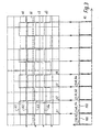
- Fig. 3 shows the signals H1 to H3 and their evaluation.
- the last signal change of one of the three sensor signals causes a commutation.
- the signal H3 changes last at the point t1 and therefore causes a commutation from -iMOT to + iMoT. In this way, a synchronous running of the three motors 22, 24, 26 is produced in a very simple manner.
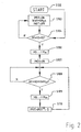
- Fig. 2 shows the corresponding flowchart.
- H3 H is stored as old in S106, and in S107, the energization of the windings 40, 42, 44 is turned on with a current of right direction, that is either + or Imot -iMOT.
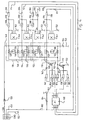
- Fig. 4 shows an example with four electronically commutated motors 110, 112, 114, 116.
- the motors 110 to 116 in contrast, two-stranded, two-pulse engines, which opposite Fig. 1 the electronics are simplified and cheaper, but the copper fill factor is reduced. None changes in the mode of operation of the motor, ie the same forces act on a rotor as on Fig. 1 ,
- the motor 110 has a two-pole permanent magnet rotor 118 and two winding strands 120, 122.
- the motor 112 has a rotor 124 and two winding strands 126, 128.
- the motor 114 has a rotor 130 and two winding strands 132, 134.
- the motor 116 has a rotor 136 and two winding strands 138, 140.
- each motor has a Hall IC 141, 142, 144 and 146, respectively.
- the Hall sensor 141 is controlled by the magnetic field of the rotor 118, the sensor 142 by the rotor 124, the sensor 144 by the rotor 130, and the sensor 146 from the rotor 136th
- the right terminals of all eight winding strands 120, 122, 126, 128, 132, 134, 138, 140 are connected via a line 148 and a diode 150 to a voltage UB, eg with +24 V.
- the diode 150 prevents a connection of the motor with wrong polarity.
- a capacitor 154 which provides reactive power to the four motors 110 through 116 during operation.
- the left terminals of the four upper strings 120, 126, 132, 138 are connected via a line 156 to the drain terminal D of an n-channel MOSFET 158 whose source S is connected to ground 152. Its gate G is connected to the drain D via the series connection of a resistor 160 and a capacitor 162. Furthermore, the gate G is connected to ground 152 via a resistor 164 and to an output 7 of a microcontroller ( ⁇ C) 168 via a resistor 166. The MOSFET 158 is thus controlled by the ⁇ C 168.
- the left terminals of the lower strings 122, 128, 134 and 140 are connected via a line 170 to the drain D of an n-channel MOSFET 172 whose source S is connected to ground 152. Between the gate and drain is an RC combination 174, 176. Also, the gate G is connected via a resistor 178 to the output 8 of the ⁇ C 168, and a resistor 180 to ground 152. Also, the MOSFET 172 is controlled by the ⁇ C 168 ,
- the ⁇ C 168 receives via a line 182 a regulated DC voltage of + 5V at its input 1, and its input 8 is connected to ground (GND) 152. Between ground 152 and the line 182 is a filter capacitor 184th
- the circuits of the Hall ICs 141, 142, 144, 146 are largely identical. These are each connected to a terminal 3A to ground 152, and to a terminal 1A they are connected to the line 148, that is to + UB. Terminal 2A is an open collector output, and therefore has a collector resistor 188 associated therewith.
- the terminal 2A is connected to a node 186, which is connected via a resistor 188 to the terminal 1A of the Hall sensor 142 and the line 148. Further, the node 186 is connected via a diode 190 to a regulated voltage of eg +5 V, and via a resistor 192 with an input 3 of ⁇ C 168.
- Diode 190 is provided in this case to limit the voltage at point 186 because input 4 of ⁇ C 168 is the so-called master pin, which lacks an internal protection diode, while processor inputs 2, 3, and 6 have internal protection diodes. (The input 4 also serves to program the processor 168.)
- the Hall sensor 141 has a node 194 which is connected via a resistor 196 to the line 148 and a resistor 198 to the input 5 of the ⁇ C 168.
- the Hall sensor 144 has a node 200 which is connected via a resistor 202 to the line 148 and via a resistor 204 to the input 3 of the ⁇ C 168.
- the Hall sensor 146 has a node 206 which is connected via a resistor 208 to the line 148 and via a resistor 210 to the input 2 of the ⁇ C 168.
- a current flows through the four strands 120, 126, 132 and 138, and during the other half turn, a current flows through the four other strands 122, 128, 134 and 140, whereby the four motors 110, 112, 114 and 116 run synchronously.
- the strands possibly also connect in series, or combined in series and in parallel.
- a speed control can be provided in addition, as well as a so-called ignition angle shift, a blocking fuse which shuts off the motors when one of them is blocked, a current limit, etc., as is known in the art for electronically commutated motors.
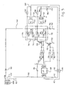
- Fig. 5 shows a variant which, so to speak, a lean version of Fig. 4 represents. Same or equivalent parts as in Fig. 4 are therefore denoted by the same reference numerals as there and not described again.
- Fig. 4 uses four motors 110, 112, 114, 116 running synchronously. at Fig. 5 Only two motors 112, 114 are used, which also run synchronously. The circuit agrees with the rest Fig. 4 which is why it will not be described again.
- the RC elements 160, 162 and 174, 176) are the Fig. 4 not shown, but can also be used. Since the inductances to be switched are smaller here, these RC elements can be omitted in many cases.
- Fig. 6 shows a circuit analog Fig. 5 in which the motors 112, 114 are constructed the same as in FIG Fig. 5 , as well as the two FETs 158 and 172 and their control, which is why the same reference numerals are used for these parts as in Fig. 5 and these matching parts and their function will not be described again for the sake of brevity.
- the position of the rotors 124, 130 is detected without a separate sensor, would be a circuit of the windings as in Fig. 5 not possible (in Fig. 5 the windings 126 and 132 are connected in parallel, as are the windings 128 and 134). That is why in Fig. 6 the terminal 126A of the winding 126 of the motor 112 is connected to the anode of a diode 220, the cathode of which is connected to the drain of the FET 158. In the same way, the terminal 132A of the winding 132 of the motor 114 is connected to the drain of the FET 158 via a diode 222.
- terminal 128A of the winding 128 of the motor 112 is connected to the drain of the FET 172 via a diode 224
- terminal 134A of the winding 134 of the motor 114 is connected to the drain of the FET 172 via a diode 226.
- the windings are at Fig. 5 connected in parallel by the diodes 220 to 226 electrically decoupled from each other, so that the voltages that occur in operation on these windings can be detected separately and used for the control of the relevant motor.
- the circuits differ from the FETs 158, 172 side Fig. 5 and 6 not, ie, when FET 158 becomes conductive, both windings 126 and 132 receive power simultaneously, and when FET 172 becomes conductive, both windings 128 and 134 receive power simultaneously.
- the FETs 158 and 172 are - via the ⁇ C 168 - controlled by a combination of the signals H2 and H3, which are supplied via the resistors 192 and 204 to the inputs 4 and 3 of the ⁇ C 168.
- the signals H2 are supplied from the output 232 of a sensorless box 234, the two inputs of which are connected to the terminals 126A, 128A of the motor 112.
- the signals H3 are supplied from the output 236 of a sensorless box 238, both of whose inputs are connected to the terminals 132A, 134A of the motor 114.
- the sensorless boxes 234, 238 are identical, which is why only the box 234 is described. They are also identical to the ones at Fig. 7 used sensorless boxes 234, 238.
- the terminal 232 is formed by the output of a comparator 242, whose non-inverting input is denoted by 244 and whose inverting input is denoted by 246. Between these inputs is a filter capacitor 248. Further, the input 244 is connected through a resistor 250, a node 252 and a capacitor 254 to the terminal 126 A, and the node 252 is connected via a resistor 256 to ground 152.
- the inverting input 246 is connected through a resistor 258, a node 260 and a capacitor 262 to the terminal 128A, and the node 260 is connected via a resistor 264 to ground 152.
- u_126A is the induced voltage in phase 126 when it is de-energized and u_128A (not shown) is analogous to the voltage on de-energized phase 128.
- the potential u_126A at the terminal 126A of the phase 126 is supplied to the differentiator formed by the capacitor 254 and the resistor 256.
- a differentiated voltage du_126A / dt is obtained, and it can be adjusted by suitable selection of the components so that their zero crossing 276 is located before the zero crossing 278 of the voltage u_126A, cf. Fig. 8 ,
- the zero crossing 276 can be evaluated in ⁇ C 168 and used as a rotor position signal.
- the time Tk is also measured from the preceding zero crossing 280 of the induced voltage u_126A and may optionally control the subsequent commutation as the time Tk '.
- the potential u_128A at terminal 128A of phase 128 is differentiated by the two components 262, 264, thereby obtaining the voltage du_128A / dt, that is, the induced voltage differential at terminal 128A, and this becomes the input 246 of comparator 242 supplied while the voltage du_126A / dt the input 244 is supplied.
- the comparator 242 changes its output. This is in Fig. 8 eg, at location 282, and this location is thus a period of time 284 before zero crossing 278 'of potential u_126A, and may serve to control commutation.
- the two resistors 250, 258 and the capacitor 248 act as two filters for the two inputs 244, 246 of the comparator 242 and prevent high-frequency interference from causing a false measurement.
- the basic principle with this type of generation of rotor position signals is therefore that the differential of a voltage induced in a currentless voltage is used as the commutation criterion, and that this commutation criterion is evaluated as a rotor position signal.
- the sensorless box 234 thus generates a signal H2, which could also be referred to as a synthetic Hall signal, ie in operation it acts as such.
- the signal H2 is also evaluated in the same way as a reverb signal and as the in Fig. 2 and 3 has been described. The same applies to the signal H3 at the output 236.
- Fig. 7 differs from Fig. 6 in that the diodes 220 to 226 of the Fig. 6 accounted for and instead of their four FETs are provided.
- a FET 250 controls the current in the winding 128. This FET is controlled via the resistor 178 from the output 6 of the ⁇ C 168.
- An FET 252 which controls the current in the winding 126 is controlled by the resistor 166 from the output 7 of the ⁇ C 168th
- An FET 254 is controlled by a resistor 166 'from the output 7 of the ⁇ C 168, i. the two FETs 252 and 254 are turned off and on synchronously.
- a FET 256 which controls the current in the winding 132 is driven by a resistor 178 'from the output 6 of the ⁇ C 168, i. the two FETs 250 and 256 are switched on and off synchronously.
Landscapes
- Engineering & Computer Science (AREA)
- Power Engineering (AREA)
- Control Of Motors That Do Not Use Commutators (AREA)
- Control Of Multiple Motors (AREA)
- Permanent Magnet Type Synchronous Machine (AREA)
Claims (8)
- Procédé pour commander le fonctionnement synchrone d'une pluralité de moteurs à commutation électronique (22, 24, 26 ; 110, 112, 114, 116) qui présentent chacun un stator avec au moins un enroulement statorique (40, 42, 44 ; 120, 122 ; 126, 128 ; 132, 134 ; 138, 140), un rotor à aimant permanent (28, 30, 32 ; 118, 124, 130, 136) et au moins un dispositif associé au moteur respectif pour saisir la position de son rotor et générer un signal de position de rotor (H1, H2, H3, H4),
et avec un dispositif d'application de courant (46 ; 158, 172) auquel les enroulements statoriques des moteurs sont connectés,
comportant les étapes suivantes :les signaux de position de rotor (H1, H2, H3, H4) sont analysés en continu pendant le fonctionnement des moteurs ;lors de l'analyse, il est déterminé quel signal de position de rotor (H1, H2, H3, H4) a changé en dernier ;s'il résulte de l'analyse que tous les rotors ont passé par une position de rotor prédéfinie, le courant est commuté en même temps dans tous les enroulements statoriques (40, 42, 44 ; 120, 122, 126, 128, 132, 134, 138, 140). - Dispositif comportant une pluralité de moteurs à commutation électronique (22, 24, 26 ; 110, 112, 114, 116) qui présentent chacun un stator avec un enroulement statorique (40, 42, 44 ; 120, 122, 126, 128, 132, 134, 138, 140), un rotor à aimant permanent (28, 30, 32 ; 118, 124, 130, 136) et au moins un dispositif associé au moteur respectif pour saisir la position de son rotor et générer un signal de position de rotor (H1, H2, H3, H4) correspondant,
et avec un dispositif d'application de courant (46 ; 158, 172) auquel les enroulements statoriques des moteurs sont connectés, le dispositif d'application de courant (46 ; 158, 172) étant conçu pour exécuter les étapes suivantes :les signaux de position de rotor (H1, H2, H3, H4) des moteurs sont analysés en continu pendant le fonctionnement des moteurs ;lors de l'analyse, il est déterminé quel signal de position de rotor (H1, H2, H3, H4) a changé en dernier ;s'il résulte de l'analyse que les rotors (28, 30, 32 ; 118, 124, 130, 136) de tous les moteurs ont passé par une position de rotor prédéfinie, le courant est commuté dans tous les enroulements statoriques. - Dispositif selon la revendication 2, dans lequel on utilise comme signaux de position de rotor des signaux qui sont prélevés sur les différents enroulements de moteur (126, 128, 132, 134) selon le principe sensorless ou sans capteur.
- Dispositif selon la revendication 3, dans lequel les différents enroulements (126, 128, 132, 134) des moteurs (112, 114) sont découplés les uns des autres au moins partiellement.
- Dispositif selon la revendication 4, dans lequel une diode (220, 222, 224, 226) est prévue dans chacune des lignes d'amenée vers les différents enroulements (126, 128, 132, 134) des moteurs (112, 114).
- Dispositif selon la revendication 4, dans lequel les différents enroulements (126, 128, 132, 134) des moteurs (112, 114) sont découplés par le fait que le courant est amené à chaque enroulement par l'intermédiaire d'un commutateur à semi-conducteurs (250, 252, 254, 256) séparé.
- Dispositif selon l'une des revendications 2 à 6 avec au moins un moteur à commutation électronique (112, 114) qui présente un stator à deux phases (126, 128) et un rotor à aimant permanent (124), lequel dernier induit lors de sa rotation des tensions dans ces phases (126, 128) du stator, la tension induite étant différentiée dans une phase sans courant du moteur et un signal de position de rotor étant généré avec la tension différentiée.
- Dispositif selon la revendication 7, dans lequel le signal généré par la différentiation est filtré avant son évaluation.
Applications Claiming Priority (2)
| Application Number | Priority Date | Filing Date | Title |
|---|---|---|---|
| DE102004059752 | 2004-12-11 | ||
| DE102005026673 | 2005-06-01 |
Publications (3)
| Publication Number | Publication Date |
|---|---|
| EP1670132A2 EP1670132A2 (fr) | 2006-06-14 |
| EP1670132A3 EP1670132A3 (fr) | 2006-11-02 |
| EP1670132B1 true EP1670132B1 (fr) | 2008-09-24 |
Family
ID=36096364
Family Applications (1)
| Application Number | Title | Priority Date | Filing Date |
|---|---|---|---|
| EP05021462A Expired - Lifetime EP1670132B1 (fr) | 2004-12-11 | 2005-09-30 | Méthode et dispositif pour contrôler la synchronisation d'un pluralité de moteurs à commutation électronique |
Country Status (3)
| Country | Link |
|---|---|
| EP (1) | EP1670132B1 (fr) |
| AT (1) | ATE409364T1 (fr) |
| DE (1) | DE502005005460D1 (fr) |
Families Citing this family (1)
| Publication number | Priority date | Publication date | Assignee | Title |
|---|---|---|---|---|
| DE202017103984U1 (de) * | 2017-07-04 | 2018-10-05 | Gebr. Bode Gmbh & Co. Kg | Schwenkschiebetür |
Family Cites Families (2)
| Publication number | Priority date | Publication date | Assignee | Title |
|---|---|---|---|---|
| JP3376477B2 (ja) * | 2000-08-01 | 2003-02-10 | 伊東電機株式会社 | 昇降装置における複数のブラシレスモータの同期方法 |
| JP4066228B2 (ja) * | 2001-10-05 | 2008-03-26 | 富士電機機器制御株式会社 | 同期運転装置 |
-
2005
- 2005-09-30 AT AT05021462T patent/ATE409364T1/de not_active IP Right Cessation
- 2005-09-30 DE DE502005005460T patent/DE502005005460D1/de not_active Expired - Lifetime
- 2005-09-30 EP EP05021462A patent/EP1670132B1/fr not_active Expired - Lifetime
Also Published As
| Publication number | Publication date |
|---|---|
| DE502005005460D1 (de) | 2008-11-06 |
| ATE409364T1 (de) | 2008-10-15 |
| EP1670132A2 (fr) | 2006-06-14 |
| EP1670132A3 (fr) | 2006-11-02 |
Similar Documents
| Publication | Publication Date | Title |
|---|---|---|
| EP0744807B1 (fr) | Procédé de limitation du courant d'un moteur à courant continu, et moteur à courant continu pour mettre en oeuvre un tel procédé | |
| DE10326606A1 (de) | Verfahren zur Kommutierung eines bürstenlosen Gleichstrommotors | |
| DE60035126T2 (de) | Verfahren zur messung der winkellage eines rotors für mehrphasige dauermagnetmotoren | |
| DE10023370A1 (de) | System zur elektronischen Kommutierung eines bürstenlosen Gleichstrommotors | |
| EP1727268A2 (fr) | Procédé pour faire fonctionner un moteur à commutation électronique et moteur pour la mise en oeuvre dudit procédé | |
| DE102009036274A1 (de) | Drehungserfassungsvorrichtung und Gleichstrommotor | |
| DE112009000209T5 (de) | Bürstenlose Vorrichtung und Steuervorrichtung | |
| DE19846831A1 (de) | Verfahren und Vorrichtung zur Ermittlung der Rotorstellung von Synchronmotoren | |
| DE102011105913A1 (de) | Elektronisch kommutierter Motor | |
| WO2005076456A1 (fr) | Moteur a commutation electronique, et procede pour le commander | |
| DE102013218041A1 (de) | Verfahren zum Betreiben eines Elektromotors | |
| DE10316539A1 (de) | Schaltungsanordnung und Verfahren zur Ansteuerung eines bürstenlosen permanenterregten Gleichstrommotors | |
| DE102015106428A1 (de) | Schaltkreis zum Bestimmen einer Position eines Bewegungselements | |
| EP1071200B1 (fr) | Moteur électroniquement commutable | |
| EP2343797A2 (fr) | Moteur monophasé commuté de manière électronique | |
| DE69803885T2 (de) | Steuerungsvorrichtung für elektrische motoren | |
| DE102016222015A1 (de) | Elektrischer Antrieb und Verfahren zum Betrieb eines Elektromotors | |
| EP1670132B1 (fr) | Méthode et dispositif pour contrôler la synchronisation d'un pluralité de moteurs à commutation électronique | |
| DE112016003094T5 (de) | Elektrowerkzeug und Verfahren zum Antreiben eines bürstenlosen Motors des Elektrowerkzeuges | |
| EP1734648A1 (fr) | Excitation asymétrique d'un moteur électrique sans capteur et sans balai | |
| DE19650908A1 (de) | Elektronisch kommutierter Motor | |
| DE102005018570A1 (de) | Kommutator für einen Elektromotor | |
| DE19519248A1 (de) | Verfahren zur Strombegrenzung bei einem Gleichstrommotor, und Gleichstrommotor zur Durchführung eines solchen Verfahrens | |
| DE102004062821A1 (de) | Verfahren und Schaltungsanordnung zur geberlosen Ermittlung der Rotorposition eines bürstenlosen Gleichstrommotors | |
| DE102004055156A1 (de) | Vorrichtung und Verfahren zur Bestimmung der Drehstellung, zum Starten, zur weiteren Kommutierung und zur Überstromerkennung eines bürstenlosen Gleichstrommotos |
Legal Events
| Date | Code | Title | Description |
|---|---|---|---|
| PUAI | Public reference made under article 153(3) epc to a published international application that has entered the european phase |
Free format text: ORIGINAL CODE: 0009012 |
|
| AK | Designated contracting states |
Kind code of ref document: A2 Designated state(s): AT BE BG CH CY CZ DE DK EE ES FI FR GB GR HU IE IS IT LI LT LU LV MC NL PL PT RO SE SI SK TR |
|
| AX | Request for extension of the european patent |
Extension state: AL BA HR MK YU |
|
| PUAL | Search report despatched |
Free format text: ORIGINAL CODE: 0009013 |
|
| AK | Designated contracting states |
Kind code of ref document: A3 Designated state(s): AT BE BG CH CY CZ DE DK EE ES FI FR GB GR HU IE IS IT LI LT LU LV MC NL PL PT RO SE SI SK TR |
|
| AX | Request for extension of the european patent |
Extension state: AL BA HR MK YU |
|
| 17P | Request for examination filed |
Effective date: 20061014 |
|
| AKX | Designation fees paid |
Designated state(s): AT BE BG CH CY CZ DE DK EE ES FI FR GB GR HU IE IS IT LI LT LU LV MC NL PL PT RO SE SI SK TR |
|
| GRAP | Despatch of communication of intention to grant a patent |
Free format text: ORIGINAL CODE: EPIDOSNIGR1 |
|
| GRAS | Grant fee paid |
Free format text: ORIGINAL CODE: EPIDOSNIGR3 |
|
| GRAA | (expected) grant |
Free format text: ORIGINAL CODE: 0009210 |
|
| AK | Designated contracting states |
Kind code of ref document: B1 Designated state(s): AT BE BG CH CY CZ DE DK EE ES FI FR GB GR HU IE IS IT LI LT LU LV MC NL PL PT RO SE SI SK TR |
|
| REG | Reference to a national code |
Ref country code: GB Ref legal event code: FG4D Free format text: NOT ENGLISH |
|
| REG | Reference to a national code |
Ref country code: CH Ref legal event code: EP |
|
| REG | Reference to a national code |
Ref country code: IE Ref legal event code: FG4D Free format text: LANGUAGE OF EP DOCUMENT: GERMAN |
|
| REF | Corresponds to: |
Ref document number: 502005005460 Country of ref document: DE Date of ref document: 20081106 Kind code of ref document: P |
|
| PG25 | Lapsed in a contracting state [announced via postgrant information from national office to epo] |
Ref country code: LT Free format text: LAPSE BECAUSE OF FAILURE TO SUBMIT A TRANSLATION OF THE DESCRIPTION OR TO PAY THE FEE WITHIN THE PRESCRIBED TIME-LIMIT Effective date: 20080924 |
|
| PG25 | Lapsed in a contracting state [announced via postgrant information from national office to epo] |
Ref country code: SI Free format text: LAPSE BECAUSE OF FAILURE TO SUBMIT A TRANSLATION OF THE DESCRIPTION OR TO PAY THE FEE WITHIN THE PRESCRIBED TIME-LIMIT Effective date: 20080924 Ref country code: LV Free format text: LAPSE BECAUSE OF FAILURE TO SUBMIT A TRANSLATION OF THE DESCRIPTION OR TO PAY THE FEE WITHIN THE PRESCRIBED TIME-LIMIT Effective date: 20080924 Ref country code: FI Free format text: LAPSE BECAUSE OF FAILURE TO SUBMIT A TRANSLATION OF THE DESCRIPTION OR TO PAY THE FEE WITHIN THE PRESCRIBED TIME-LIMIT Effective date: 20080924 |
|
| NLV1 | Nl: lapsed or annulled due to failure to fulfill the requirements of art. 29p and 29m of the patents act | ||
| BERE | Be: lapsed |
Owner name: EBM-PAPST ST. GEORGEN G.M.B.H. & CO. KG Effective date: 20080930 |
|
| REG | Reference to a national code |
Ref country code: IE Ref legal event code: FD4D |
|
| PG25 | Lapsed in a contracting state [announced via postgrant information from national office to epo] |
Ref country code: MC Free format text: LAPSE BECAUSE OF NON-PAYMENT OF DUE FEES Effective date: 20080930 Ref country code: BG Free format text: LAPSE BECAUSE OF FAILURE TO SUBMIT A TRANSLATION OF THE DESCRIPTION OR TO PAY THE FEE WITHIN THE PRESCRIBED TIME-LIMIT Effective date: 20081224 Ref country code: ES Free format text: LAPSE BECAUSE OF FAILURE TO SUBMIT A TRANSLATION OF THE DESCRIPTION OR TO PAY THE FEE WITHIN THE PRESCRIBED TIME-LIMIT Effective date: 20090104 |
|
| PG25 | Lapsed in a contracting state [announced via postgrant information from national office to epo] |
Ref country code: SK Free format text: LAPSE BECAUSE OF FAILURE TO SUBMIT A TRANSLATION OF THE DESCRIPTION OR TO PAY THE FEE WITHIN THE PRESCRIBED TIME-LIMIT Effective date: 20080924 Ref country code: NL Free format text: LAPSE BECAUSE OF FAILURE TO SUBMIT A TRANSLATION OF THE DESCRIPTION OR TO PAY THE FEE WITHIN THE PRESCRIBED TIME-LIMIT Effective date: 20080924 Ref country code: CZ Free format text: LAPSE BECAUSE OF FAILURE TO SUBMIT A TRANSLATION OF THE DESCRIPTION OR TO PAY THE FEE WITHIN THE PRESCRIBED TIME-LIMIT Effective date: 20080924 Ref country code: RO Free format text: LAPSE BECAUSE OF FAILURE TO SUBMIT A TRANSLATION OF THE DESCRIPTION OR TO PAY THE FEE WITHIN THE PRESCRIBED TIME-LIMIT Effective date: 20080924 Ref country code: IS Free format text: LAPSE BECAUSE OF FAILURE TO SUBMIT A TRANSLATION OF THE DESCRIPTION OR TO PAY THE FEE WITHIN THE PRESCRIBED TIME-LIMIT Effective date: 20090124 |
|
| PG25 | Lapsed in a contracting state [announced via postgrant information from national office to epo] |
Ref country code: IE Free format text: LAPSE BECAUSE OF FAILURE TO SUBMIT A TRANSLATION OF THE DESCRIPTION OR TO PAY THE FEE WITHIN THE PRESCRIBED TIME-LIMIT Effective date: 20080924 Ref country code: EE Free format text: LAPSE BECAUSE OF FAILURE TO SUBMIT A TRANSLATION OF THE DESCRIPTION OR TO PAY THE FEE WITHIN THE PRESCRIBED TIME-LIMIT Effective date: 20080924 Ref country code: BE Free format text: LAPSE BECAUSE OF NON-PAYMENT OF DUE FEES Effective date: 20080930 Ref country code: DK Free format text: LAPSE BECAUSE OF FAILURE TO SUBMIT A TRANSLATION OF THE DESCRIPTION OR TO PAY THE FEE WITHIN THE PRESCRIBED TIME-LIMIT Effective date: 20080924 |
|
| PLBE | No opposition filed within time limit |
Free format text: ORIGINAL CODE: 0009261 |
|
| STAA | Information on the status of an ep patent application or granted ep patent |
Free format text: STATUS: NO OPPOSITION FILED WITHIN TIME LIMIT |
|
| PG25 | Lapsed in a contracting state [announced via postgrant information from national office to epo] |
Ref country code: IT Free format text: LAPSE BECAUSE OF FAILURE TO SUBMIT A TRANSLATION OF THE DESCRIPTION OR TO PAY THE FEE WITHIN THE PRESCRIBED TIME-LIMIT Effective date: 20080924 |
|
| 26N | No opposition filed |
Effective date: 20090625 |
|
| PG25 | Lapsed in a contracting state [announced via postgrant information from national office to epo] |
Ref country code: AT Free format text: LAPSE BECAUSE OF NON-PAYMENT OF DUE FEES Effective date: 20080930 |
|
| PG25 | Lapsed in a contracting state [announced via postgrant information from national office to epo] |
Ref country code: SE Free format text: LAPSE BECAUSE OF FAILURE TO SUBMIT A TRANSLATION OF THE DESCRIPTION OR TO PAY THE FEE WITHIN THE PRESCRIBED TIME-LIMIT Effective date: 20081224 |
|
| REG | Reference to a national code |
Ref country code: CH Ref legal event code: PL |
|
| PG25 | Lapsed in a contracting state [announced via postgrant information from national office to epo] |
Ref country code: PL Free format text: LAPSE BECAUSE OF FAILURE TO SUBMIT A TRANSLATION OF THE DESCRIPTION OR TO PAY THE FEE WITHIN THE PRESCRIBED TIME-LIMIT Effective date: 20080924 |
|
| PG25 | Lapsed in a contracting state [announced via postgrant information from national office to epo] |
Ref country code: HU Free format text: LAPSE BECAUSE OF FAILURE TO SUBMIT A TRANSLATION OF THE DESCRIPTION OR TO PAY THE FEE WITHIN THE PRESCRIBED TIME-LIMIT Effective date: 20090325 Ref country code: CY Free format text: LAPSE BECAUSE OF FAILURE TO SUBMIT A TRANSLATION OF THE DESCRIPTION OR TO PAY THE FEE WITHIN THE PRESCRIBED TIME-LIMIT Effective date: 20080924 Ref country code: LU Free format text: LAPSE BECAUSE OF NON-PAYMENT OF DUE FEES Effective date: 20080930 |
|
| PG25 | Lapsed in a contracting state [announced via postgrant information from national office to epo] |
Ref country code: TR Free format text: LAPSE BECAUSE OF FAILURE TO SUBMIT A TRANSLATION OF THE DESCRIPTION OR TO PAY THE FEE WITHIN THE PRESCRIBED TIME-LIMIT Effective date: 20080924 |
|
| PG25 | Lapsed in a contracting state [announced via postgrant information from national office to epo] |
Ref country code: GR Free format text: LAPSE BECAUSE OF FAILURE TO SUBMIT A TRANSLATION OF THE DESCRIPTION OR TO PAY THE FEE WITHIN THE PRESCRIBED TIME-LIMIT Effective date: 20081225 Ref country code: CH Free format text: LAPSE BECAUSE OF NON-PAYMENT OF DUE FEES Effective date: 20090930 Ref country code: LI Free format text: LAPSE BECAUSE OF NON-PAYMENT OF DUE FEES Effective date: 20090930 |
|
| PG25 | Lapsed in a contracting state [announced via postgrant information from national office to epo] |
Ref country code: PT Free format text: LAPSE BECAUSE OF FAILURE TO SUBMIT A TRANSLATION OF THE DESCRIPTION OR TO PAY THE FEE WITHIN THE PRESCRIBED TIME-LIMIT Effective date: 20080924 |
|
| PGFP | Annual fee paid to national office [announced via postgrant information from national office to epo] |
Ref country code: FR Payment date: 20140728 Year of fee payment: 10 |
|
| REG | Reference to a national code |
Ref country code: DE Ref legal event code: R084 Ref document number: 502005005460 Country of ref document: DE |
|
| PGFP | Annual fee paid to national office [announced via postgrant information from national office to epo] |
Ref country code: GB Payment date: 20150904 Year of fee payment: 11 |
|
| REG | Reference to a national code |
Ref country code: FR Ref legal event code: ST Effective date: 20160531 |
|
| PG25 | Lapsed in a contracting state [announced via postgrant information from national office to epo] |
Ref country code: FR Free format text: LAPSE BECAUSE OF NON-PAYMENT OF DUE FEES Effective date: 20150930 |
|
| PGFP | Annual fee paid to national office [announced via postgrant information from national office to epo] |
Ref country code: DE Payment date: 20160901 Year of fee payment: 12 |
|
| GBPC | Gb: european patent ceased through non-payment of renewal fee |
Effective date: 20160930 |
|
| PG25 | Lapsed in a contracting state [announced via postgrant information from national office to epo] |
Ref country code: GB Free format text: LAPSE BECAUSE OF NON-PAYMENT OF DUE FEES Effective date: 20160930 |
|
| REG | Reference to a national code |
Ref country code: DE Ref legal event code: R119 Ref document number: 502005005460 Country of ref document: DE |
|
| PG25 | Lapsed in a contracting state [announced via postgrant information from national office to epo] |
Ref country code: DE Free format text: LAPSE BECAUSE OF NON-PAYMENT OF DUE FEES Effective date: 20180404 |