EP1670290A1 - Appareil de cuisson muni d'un dispositf générateur de micro-ondes - Google Patents
Appareil de cuisson muni d'un dispositf générateur de micro-ondes Download PDFInfo
- Publication number
- EP1670290A1 EP1670290A1 EP05026912A EP05026912A EP1670290A1 EP 1670290 A1 EP1670290 A1 EP 1670290A1 EP 05026912 A EP05026912 A EP 05026912A EP 05026912 A EP05026912 A EP 05026912A EP 1670290 A1 EP1670290 A1 EP 1670290A1
- Authority
- EP
- European Patent Office
- Prior art keywords
- cooking appliance
- cooking
- coaxial
- appliance according
- cooking chamber
- Prior art date
- Legal status (The legal status is an assumption and is not a legal conclusion. Google has not performed a legal analysis and makes no representation as to the accuracy of the status listed.)
- Granted
Links
- 238000010411 cooking Methods 0.000 title claims abstract description 152
- 230000008878 coupling Effects 0.000 claims abstract description 35
- 238000010168 coupling process Methods 0.000 claims abstract description 35
- 238000005859 coupling reaction Methods 0.000 claims abstract description 35
- 239000004020 conductor Substances 0.000 claims description 62
- 230000005855 radiation Effects 0.000 claims description 28
- 239000011810 insulating material Substances 0.000 claims description 15
- 238000003780 insertion Methods 0.000 claims description 14
- 230000037431 insertion Effects 0.000 claims description 14
- 239000000969 carrier Substances 0.000 claims description 10
- 239000011521 glass Substances 0.000 claims description 6
- 238000001816 cooling Methods 0.000 claims description 4
- 239000003990 capacitor Substances 0.000 claims description 3
- 239000000919 ceramic Substances 0.000 claims description 3
- 239000012774 insulation material Substances 0.000 claims description 3
- 239000007787 solid Substances 0.000 claims description 3
- 230000005540 biological transmission Effects 0.000 abstract 2
- 238000000605 extraction Methods 0.000 description 10
- 238000010438 heat treatment Methods 0.000 description 6
- 230000001105 regulatory effect Effects 0.000 description 4
- 238000001514 detection method Methods 0.000 description 3
- 230000005670 electromagnetic radiation Effects 0.000 description 3
- 239000000463 material Substances 0.000 description 3
- 238000005259 measurement Methods 0.000 description 2
- 230000032258 transport Effects 0.000 description 2
- 206010041662 Splinter Diseases 0.000 description 1
- 230000006978 adaptation Effects 0.000 description 1
- 238000013461 design Methods 0.000 description 1
- 239000003989 dielectric material Substances 0.000 description 1
- 238000001035 drying Methods 0.000 description 1
- 238000005516 engineering process Methods 0.000 description 1
- 238000011156 evaluation Methods 0.000 description 1
- 238000000265 homogenisation Methods 0.000 description 1
- 238000009434 installation Methods 0.000 description 1
- 238000009413 insulation Methods 0.000 description 1
- 238000002955 isolation Methods 0.000 description 1
- 239000007788 liquid Substances 0.000 description 1
- 238000002844 melting Methods 0.000 description 1
- 230000008018 melting Effects 0.000 description 1
- 239000002184 metal Substances 0.000 description 1
- 238000000034 method Methods 0.000 description 1
- 238000003303 reheating Methods 0.000 description 1
- 238000010257 thawing Methods 0.000 description 1
- 238000012795 verification Methods 0.000 description 1
Images


Classifications
-
- H—ELECTRICITY
- H05—ELECTRIC TECHNIQUES NOT OTHERWISE PROVIDED FOR
- H05B—ELECTRIC HEATING; ELECTRIC LIGHT SOURCES NOT OTHERWISE PROVIDED FOR; CIRCUIT ARRANGEMENTS FOR ELECTRIC LIGHT SOURCES, IN GENERAL
- H05B6/00—Heating by electric, magnetic or electromagnetic fields
- H05B6/64—Heating using microwaves
- H05B6/6402—Aspects relating to the microwave cavity
-
- H—ELECTRICITY
- H05—ELECTRIC TECHNIQUES NOT OTHERWISE PROVIDED FOR
- H05B—ELECTRIC HEATING; ELECTRIC LIGHT SOURCES NOT OTHERWISE PROVIDED FOR; CIRCUIT ARRANGEMENTS FOR ELECTRIC LIGHT SOURCES, IN GENERAL
- H05B6/00—Heating by electric, magnetic or electromagnetic fields
- H05B6/64—Heating using microwaves
- H05B6/6408—Supports or covers specially adapted for use in microwave heating apparatus
-
- H—ELECTRICITY
- H05—ELECTRIC TECHNIQUES NOT OTHERWISE PROVIDED FOR
- H05B—ELECTRIC HEATING; ELECTRIC LIGHT SOURCES NOT OTHERWISE PROVIDED FOR; CIRCUIT ARRANGEMENTS FOR ELECTRIC LIGHT SOURCES, IN GENERAL
- H05B6/00—Heating by electric, magnetic or electromagnetic fields
- H05B6/64—Heating using microwaves
- H05B6/66—Circuits
- H05B6/68—Circuits for monitoring or control
- H05B6/688—Circuits for monitoring or control for thawing
-
- H—ELECTRICITY
- H05—ELECTRIC TECHNIQUES NOT OTHERWISE PROVIDED FOR
- H05B—ELECTRIC HEATING; ELECTRIC LIGHT SOURCES NOT OTHERWISE PROVIDED FOR; CIRCUIT ARRANGEMENTS FOR ELECTRIC LIGHT SOURCES, IN GENERAL
- H05B6/00—Heating by electric, magnetic or electromagnetic fields
- H05B6/64—Heating using microwaves
- H05B6/70—Feed lines
- H05B6/702—Feed lines using coaxial cables
-
- H—ELECTRICITY
- H05—ELECTRIC TECHNIQUES NOT OTHERWISE PROVIDED FOR
- H05B—ELECTRIC HEATING; ELECTRIC LIGHT SOURCES NOT OTHERWISE PROVIDED FOR; CIRCUIT ARRANGEMENTS FOR ELECTRIC LIGHT SOURCES, IN GENERAL
- H05B6/00—Heating by electric, magnetic or electromagnetic fields
- H05B6/64—Heating using microwaves
- H05B6/70—Feed lines
- H05B6/705—Feed lines using microwave tuning
-
- Y—GENERAL TAGGING OF NEW TECHNOLOGICAL DEVELOPMENTS; GENERAL TAGGING OF CROSS-SECTIONAL TECHNOLOGIES SPANNING OVER SEVERAL SECTIONS OF THE IPC; TECHNICAL SUBJECTS COVERED BY FORMER USPC CROSS-REFERENCE ART COLLECTIONS [XRACs] AND DIGESTS
- Y02—TECHNOLOGIES OR APPLICATIONS FOR MITIGATION OR ADAPTATION AGAINST CLIMATE CHANGE
- Y02B—CLIMATE CHANGE MITIGATION TECHNOLOGIES RELATED TO BUILDINGS, e.g. HOUSING, HOUSE APPLIANCES OR RELATED END-USER APPLICATIONS
- Y02B40/00—Technologies aiming at improving the efficiency of home appliances, e.g. induction cooking or efficient technologies for refrigerators, freezers or dish washers
Definitions
- the present invention relates to a cooking appliance having a cooking chamber, a microwave generating device and at least one coaxial or strip conductor within the cooking chamber, which is connected to the microwave generating device and can be coupled out via the microwave radiation generated by the microwave generating device within the cooking chamber.
- microwave generating devices may be integrated in a conventional circulating air cooking appliance, or cooking appliances are known with which only cooking based on microwave radiation is possible.
- a particular problem for Mikrowellengarella is the uniform energy input over several treatment or insertion levels for food. Often it is only possible to use only one or two insertion levels for heating the food with the aid of microwave energy, usually for each usable shelf level own microwave generating device (for example, comprising a magnetron) is used. Conventionally, the microwave radiation is transported from the microwave generating device to the cooking chamber via waveguides, which require a relatively large amount of space. In particular, when several insertion levels are to be applied in a cooking chamber of a cooking appliance with microwave power, the required space for these waveguide is disadvantageous.
- WO 01/82653 A1 discloses a microwave cooking appliance having a plurality of levels, each of which can be irradiated with microwaves.
- the Mikrowellengar réelle on each level on a waveguide with a plurality of openings, the microwave radiation radiate horizontally on introduced into the levels of food.
- Each level has a separate microwave generator.
- US 4,329,557 describes a microwave cooking appliance which may have multiple levels. Microwave radiation enters via an opening in a cooking chamber, is deflected by a metal sheet and can be passed via laterally arranged waveguide from an upper portion of the cooking chamber to a lower portion of the cooking chamber.
- the waveguides may have slots into which a board for receiving a food can be inserted. Through the waveguide is to be achieved, that even in the lower portion of the microwave cooking appliance introduced food can be heated evenly.
- a Mikrowellengarêt with a cooking chamber in which microwave radiation can be introduced via a plurality of openings.
- waveguides can be closed by a microwave source to the openings by means of closure means.
- a Mikrowellengarêt is known in which a food can be detected in a cooking chamber characterized in that over a small opening of the cooking chamber reflected microwave radiation can be directed to the outside and detected by a sensor. About the energy of the exiting microwave radiation can be concluded whether and what is a food inside the cooking chamber.
- US Pat. No. 4,507,531 discloses a microwave cooking appliance with a cooking chamber in which an output power of a magnetron is regulated via an anode current as a controlled variable so that a cooking process can always be carried out in the same way since the power of the magnetron can be precisely controlled.
- a cooking appliance with a microwave generating device is also known from US 2004/0004074 A1, wherein this Mikrowellengarmeld a special microwave decoupling for Homogenization of the energy input in food to be cooked in the cooking uses. More precisely, the cooking chamber of this cooking appliance is equipped with a plurality of microwave discharge openings, wherein, for example, a first discharge opening forwards electromagnetic radiation via reflection to a second discharge opening in the cooking space. Reflected electromagnetic radiation can also be forwarded via the second emission opening to a third emission opening. Finally, electromagnetic radiation reflected via the third emission opening can be forwarded to a load whose temperature can be measured.
- the various radiation openings of the microwave cooking appliance are in operative connection with a strip conductor which is arranged outside the cooking chamber. The decoupling of the radiation takes place at the cooking chamber walls.
- a generic cooking appliance is known for example from US 4,600,822, although a microstrip line for microwave heating, but without details of the arrangement thereof are disclosed in the cooking appliance.
- a generic cooking appliance is also known from US 2004/0188429 A1, but only the transport of microwaves to the cooking space via a coaxial cable is disclosed.
- US 5,334,403 relates to an apparatus for thawing, reheating and drying products in a sealed treatment room by moving a microwave source above a product layer.
- No. 6,323,471 B1 relates inter alia to microwave heating under reduced pressure of an object to be dried, to be concentrated, to be defrosted, to be roasted or sterilized using reflector plates for uniform heating.
- U1 relates to a microwave oven with a multi-storey and rotatably designed tray rack for receiving food to be treated with the microwaves.
- the present invention has for its object to further develop the generic cooking appliance such that microwave radiation can be passed in a space-saving manner from the microwave generating device to be irradiated food. Also, the positioning of the microwave generating device should be as flexible as possible without causing leaks or stability problems. Furthermore, the decoupling of the microwave radiation in the oven should be as close as possible to the food.
- the at least one coaxial or strip conductor is integrated in at least one member of the cooking appliance in the form of a support or a solid support within the cooking chamber or in at least one insertable into the cooking accessory, the carrier for carrying retractable Gar variouser, plates, sheets and / or trays is used and / or the accessory includes a Einitatigestell, a cellar trolley or a Tellerregeneriergestell.
- At least one contact and / or coupling device for connecting the coaxial or strip conductor, directly or indirectly, with the microwave generating device in the region of a cooking chamber wall.
- connection between the contact and / or coupling device and the coaxial or strip conductor in particular automatically, can be produced by introducing the Zuber Anlagenteils in the oven.
- the contact and / or coupling device comprises a passage through the cooking chamber wall, preferably in the region of the bottom surface of the cooking appliance, and / or a splitter.
- the invention also proposes that the contact and / or coupling device for coupling at least one coaxial conductor, in particular a first coaxial cable, in the cooking chamber with a coaxial conductor of a second coaxial cable outside the cooking chamber is designed via a plug connection.
- a connecting element preferably in conjunction with the coaxial conductor of the first coaxial cable
- a Koaxialpin preferably in conjunction with the coaxial conductor of the second coaxial cable, at least partially guided by an insulating material and a cooking chamber wall.
- connection element can be connected or connected to the accessory.
- the invention also proposes that the coaxial pin runs at least partially in the connecting element, which preferably has the shape of a bolt.
- the insulating material has a recess into which the connecting element can be inserted.
- the invention proposes that in the bottom region of the insulating material of Koaxialpin is arranged.
- the insulation material comprises a ceramic, such as steatite or glass.
- Preferred cooking devices according to the invention are characterized in that the coaxial conductor in the cooking chamber is at least partially provided by a conductor, preferably in the form of a circular conductor, in a part of the member representing a mass, preferably in the form of a U-shaped profile.
- the microwave generating device comprising at least one magnetron, at least one high-voltage transformer, at least one heating transformer, at least one capacitor, at least one diode, at least one switched-mode power supply and / or a cooling device outside the cooking chamber, in particular outside the appliance body of the cooking appliance, preferably in a lower cabinet, at least partially arranged.
- embodiments are also proposed, which are characterized by at least one antenna in operative connection with the coaxial or strip conductor, in particular welded to the circular conductor, for the radiation of microwaves in the cooking chamber.
- the member, in particular the accessory, with at least one insertion strip for at least one food support and at least one decoupling point on the microwave radiation from the coaxial or strip conductor in the cooking chamber, in particular via an antenna, is decoupled, is in operative connection, wherein preferably a plurality of coupling-out points and a plurality of insertion strips are arranged within the cooking chamber, and aligned with each other.
- the extraction points are aligned for coupling out of microwave radiation substantially parallel to treatment levels for food and / or food supports.
- each insertion strip between two carriers in particular in the form of Horwerkgestell GmbH runs, which are connectable to at least one contact and / or coupling device, preferably with the interposition of a splitter.
- the member, in particular the accessory is disposed adjacent to a provided inside the cooking fan impeller, is detachable and / or movable.
- the invention is therefore based on the surprising finding that it is possible with the cooking appliance according to the invention to reduce the space requirements for directing microwave radiation into a cooking space in that coaxial or strip conductors are used within the cooking chamber, which is used to decouple microwave radiation in the oven are integrated in a solid support within the cooking chamber or in an insertable into a cooking accessory. It is particularly advantageous if the coaxial conductors are formed by round conductors which run in grounded U-shaped profiles of the carrier or accessory, in particular in the form of a tray rack. The use of such coaxial or strip conductors within the cooking chamber allows flexible adaptation to the cooking product introduced into the cooking chamber, in particular its placement, so that the coupling of the microwave radiation can be as close as possible to the food.
- the carrier or the accessory may preferably have one or more extraction points which can be arranged at different heights within the cooking chamber in order to optimize the extraction of microwave radiation with respect to treatment levels for food to be cooked.
- an antenna can be directly welded to a round conductor, which antenna can pass through an opening in a profile of the oven rack.
- coaxial or strip conductors are integrated in several carriers or accessories, the individual outcoupling points can be adjusted so that they face each other, for example diagonally.
- Coaxial or strip conductors may also be integrated in all carriers or supports of accessories. Will the beam direction of the microwave rays turn off led out of the extraction point parallel to the treatment levels, a particularly good energy input can be achieved in the food to be heated.
- a contact and / or coupling device is provided, via which the accessory is connected to a microwave generating device arranged outside the cooking chamber.
- a contact and / or coupling device is preferably arranged in the region of a housing wall of the cooking chamber, which is followed by the coaxial or strip conductor within the cooking chamber. Outside the cooking chamber can be used as a connecting line between the microwave generating device and the contact and / or coupling a coaxial cable.
- the contact and / or coupling device can advantageously electrically and / or magnetically shielded, vapor-tight and / or up to a temperature of at least 250 ° C, preferably 300 ° C, temperature stable. It is also preferred that the coaxial or strip conductor is temperature-resistant up to a temperature of at least 250 ° C., preferably 300 ° C., and / or transports a power of about 1KW.
- microwave energy from a microwave generating device to a housing wall of a cooking chamber, for example via coaxial cable can be passed, which have not been used in cooking appliances and at powers of about 1 kW.
- Coaxial cable routing allows for flexible design and positioning of the microwave generating components which, in addition to a magnetron, may also include a high voltage transformer, a heating transformer, capacitors, diodes, and a switched mode power supply. Also, the use of coaxial cables allows flexible cooling of these components, e.g. also outside of the actual Garellakorpus in a dedicated cabinet or the like.
- the coupling and / or coupling device can be used to couple a coaxial pin of a coaxial cable with a coaxial conductor, for example, also interchangeable, arranged in the cooking chamber through a housing wall.
- the coaxial conductor within the cooking chamber is used for this purpose via a connecting element in insulating material and can at any time by any other coaxial conductor with corresponding connection elements be replaced. Due to this interchangeability, the cooking appliance can be used more flexibly.
- the contact and / or coupling device according to the invention also makes it possible to check the microwave compatibility of, for example, an accessory of the cooking appliance. Is a plugged into the recess of the insulating material connecting element of the accessory is not microwave compatible, can be switched off via a control or regulating device, which is in operative connection with a verification device, the microwave generating device. This can prevent damage to the cooking appliance and accessories. In other words, the cooking appliance according to the invention is also safe to operate with standard accessories, ie without coupling of microwaves.
- the number of carriers or accessories in which coaxial or strip conductors are integrated can be adjusted depending on the size of the cooking appliance or the size of drawer containers in which food is to be heated.
- a cooking appliance according to the invention can be provided with a load recognition device, wherein the load recognition device can preferably carry out an evaluation of absorbed and / or reflected microwave radiation, an anode current measurement at the microwave generation device or a measurement of an electromagnetic interference, in particular using the Bluetooth technology.
- the load recognition device can preferably carry out an evaluation of absorbed and / or reflected microwave radiation, an anode current measurement at the microwave generation device or a measurement of an electromagnetic interference, in particular using the Bluetooth technology.
- the different areas of the cooking chamber eg. The different treatment levels for food to be controlled separately.
- the power control device for particularly individual regulation of the power of microwave radiation at each output point thereof in the cooking chamber increases the cooking precision.
- the power control device may comprise at least one closure means for the extraction points for partially or completely closing the same.
- the coaxial or strip conductor can even be arranged in a space-saving manner, similar to or around a gas heat exchanger, on a fan wheel.
- a control or regulating device in operative connection with the microwave generating device, the load detection device, the contact and / or coupling device, the checking device, the power control device, at least one extraction point, at least one closure means and / or at least one sensor, preferably for determining the temperature within the cooking chamber, be provided at a cooking appliance according to the invention.
- FIG. 1 shows a cooking chamber 1 of a cooking appliance 2 according to the invention, which is bounded by a bottom surface 3, side walls 4 and a cover 5, wherein an opening 6 is defined, which can be closed for example by a cooking appliance door, not shown.
- an opening 6 is defined, which can be closed for example by a cooking appliance door, not shown.
- Within the cooking chamber 1 four carriers 7 are arranged, of which three can be recognized in FIG.
- On the straps 7 slide-8 are arranged in the example, sheets for supporting Gar organizationsern (not shown) or the like inserted and thus can be placed in the oven.
- At least one carrier 7 is designed with a coaxial conductor, ie, a coaxial conductor is integrated in the carrier 7.
- the executed as a coaxial conductor carrier 7 has a plurality of extraction points 9, which pass into antennas, can be discharged via the microwave radiation from the coaxial into the cooking chamber 1.
- the arrangement of each extraction point 9 or antenna corresponds to an insertion strip 8, so that at least one extraction point 9 is present along the support 7 for each cooking container inserted on an insertion strip 8.
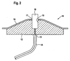
- FIG. 2 shows a contact and / or coupling device 10 for connecting the carrier 7 together with its coaxial conductor, in the region of the bottom surface 3 of the cooking device 2 of Figure 1, with a microwave generating device, not shown, by a coaxial pin 13 of a coaxial cable in an insulating material 2 14 is inserted.
- the coaxial cable 14 may be attached to the insulating material 12 via any attachment device (not shown).
- a recess 15 is provided, in the bottom region of which the tip of the coaxial pin 13 rests.
- the insulating material 12, which may be, for example, a ceramic, such as steatite or glass, is arranged in a bulge of the cooking chamber wall 16 of the bottom surface 3 of the cooking appliance shown in FIG.
- This cooking chamber wall 16 has an opening 17 which lies over the recess 15 of the insulating material 12.
- the connecting element can be a bolt 18. If the bolt 18 is inserted into the recess 15 of the insulating material 12, a contact connection between the tip of the coaxial pin 13 and the connecting element 18 of the coaxial conductor of the carrier 7 is made possible.
- the supplied via the coaxial cable 14 microwave radiation can be transmitted through the contact and / or coupling device to the connection element 18 of the coaxial conductor to be finally decoupled within the cooking chamber 1 to the extraction point 9 via antennas.
- the decoupling can take place regulated via a power control device, not shown.
- coaxial conductors may be attached to the contact and / or coupling means with respective terminal members to enable coupling via the coaxial pin 13 and coaxial cable 14 to the microwave generating means.
- the coupling interchangeable coaxial conductor (accessories) to the microwave generating device and on the other hand a flexible connection between two conductors (coaxial pin and coaxial conductor) provided in the interior of the insulating material 2.
- a coaxial conductor for transporting microwaves into a cooking space can also be integrated into a tray rack, which in turn has two carriers 7'a, 7'b running substantially vertically in the cooking space and a plurality of substantially horizontally extending insert bars 8 ', only one of which is shown. Both the carriers 7'a, 7'b and the insertion strips 8 'are formed substantially U-shaped for this purpose, accommodate in their interior round conductors 103'a, 103'b, 103'c and are grounded.
- coaxial conductors are provided by the tray rack 7'a, 7'b, 8 'together with the round conductors 103'a, 103'b, 103'c, in a particularly cost-saving and space-saving manner.
- the U-configuration of the tray rack profile also allows drainage of liquid.
- microwave energy can be fed via a microwave generating device, not shown, into a contact and / or coupling device 100 'which is arranged in the bottom of a cooking appliance (not shown) and in turn not only a feedthrough 101'. for microwave but also a T-shaped splitter 102 'to microwave energy to the round conductor 103'a, 103'b in the two carriers 7'a, 7'b of the oven rack to come, so that the tray rack to the contact and / Coupling 100 'rotatably installed in a cooking chamber.
- the feedthroughs 101 'as well as the splitter 102' must be conducted in isolation through the cooking chamber bottom, without a corresponding insulation being shown in detail in FIG.
- antennas 103'a, 103'b, 103'c antennas not shown are attachable, in particular weldable.
- the antennas can be provided either in the region of the two carriers 7'a and 7'b or the insertion strips 8 '.
Landscapes
- Physics & Mathematics (AREA)
- Electromagnetism (AREA)
- Electric Ovens (AREA)
- Constitution Of High-Frequency Heating (AREA)
- Cookers (AREA)
Applications Claiming Priority (1)
| Application Number | Priority Date | Filing Date | Title |
|---|---|---|---|
| DE102004059900A DE102004059900B3 (de) | 2004-12-13 | 2004-12-13 | Gargerät mit Mikrowellenerzeugungseinrichtung |
Publications (2)
| Publication Number | Publication Date |
|---|---|
| EP1670290A1 true EP1670290A1 (fr) | 2006-06-14 |
| EP1670290B1 EP1670290B1 (fr) | 2007-11-21 |
Family
ID=35976616
Family Applications (1)
| Application Number | Title | Priority Date | Filing Date |
|---|---|---|---|
| EP05026912A Expired - Lifetime EP1670290B1 (fr) | 2004-12-13 | 2005-12-09 | Appareil de cuisson muni d'un dispositf générateur de micro-ondes |
Country Status (3)
| Country | Link |
|---|---|
| EP (1) | EP1670290B1 (fr) |
| JP (1) | JP4237178B2 (fr) |
| DE (2) | DE102004059900B3 (fr) |
Cited By (5)
| Publication number | Priority date | Publication date | Assignee | Title |
|---|---|---|---|---|
| DE102007035357A1 (de) | 2007-07-27 | 2009-02-05 | Rational Ag | Antennenstruktur für ein Gargerät und Gargerät mit solch einer Antennenstruktur |
| DE102007035359A1 (de) | 2007-07-27 | 2009-02-05 | Rational Ag | Kopplungsvorrichtung zur Mikrowellenübertragung in einem Nahrungsmittelbehandlungsgerät sowie Nahrungsmittelbehandlungsgerät und Zubehörteil mit solch einer Kopplungsvorrichtung |
| EP3177109A1 (fr) * | 2015-12-04 | 2017-06-07 | Electrolux Appliances Aktiebolag | Four à micro-ondes |
| DE102017127172A1 (de) | 2017-11-17 | 2019-05-23 | Fricke Und Mallah Microwave Technology Gmbh | Erhitzungshomogener Kombigarofen |
| WO2020001967A1 (fr) * | 2018-06-28 | 2020-01-02 | BSH Hausgeräte GmbH | Four à micro-ondes électro-ménager et procédé pour la fabrication d'un guide de micro-ondes |
Families Citing this family (6)
| Publication number | Priority date | Publication date | Assignee | Title |
|---|---|---|---|---|
| DE102006012041A1 (de) * | 2006-03-16 | 2007-09-20 | Fraunhofer-Gesellschaft zur Förderung der angewandten Forschung e.V. | Mikrowellenofen |
| DE102006046422B4 (de) * | 2006-09-22 | 2021-01-14 | Wiesheu Gmbh | Ofen zur Wärmebehandlung von Lebensmitteln |
| DE102007051638B8 (de) | 2007-10-26 | 2010-06-10 | Rational Ag | Verfahren zur Erkennung des Beladungszustandes eines Gargerätes mit Mikrowellengaren und Gargerät zur Durchführung solch eines Verfahrens |
| EP2148553B1 (fr) | 2008-07-21 | 2011-03-02 | Topinox Sarl | Procédé et dispositif de surveillance de fuites de micro-ondes dans un appareil de cuisson |
| EP2152047A1 (fr) | 2008-08-04 | 2010-02-10 | Topinox Sarl | Dispositif de sécurité destiné à la détection de rayonnement de fuite |
| DE102013114066A1 (de) * | 2013-12-16 | 2015-06-18 | Topinox Sarl. | Gebläserad, Gargerät und Garverfahren |
Citations (5)
| Publication number | Priority date | Publication date | Assignee | Title |
|---|---|---|---|---|
| FR1545143A (fr) * | 1966-11-21 | 1968-11-08 | Technology Instr Corp Of Calif | Appareil de chauffage à hyperfréquences |
| US4329557A (en) * | 1979-12-07 | 1982-05-11 | General Electric Company | Microwave oven with improved energy distribution |
| EP0373608A2 (fr) * | 1988-12-14 | 1990-06-20 | Mitsubishi Denki Kabushiki Kaisha | Appareil de chauffage à micro-ondes |
| EP0429822A1 (fr) * | 1989-11-29 | 1991-06-05 | ZANUSSI GRANDI IMPIANTI S.p.A. | Four combiné à micro-ondes et a convection forcée |
| US6002120A (en) * | 1995-08-25 | 1999-12-14 | Moulinex S.A. | Electric microwave oven with improved energy distribution |
Family Cites Families (10)
| Publication number | Priority date | Publication date | Assignee | Title |
|---|---|---|---|---|
| DE1937470U (de) * | 1965-12-10 | 1966-04-28 | Fritz Hellige & Co G M B H Fab | Mikrowellenherd mit mherstockiger drehhorde. |
| US4507531A (en) * | 1981-10-30 | 1985-03-26 | Raytheon Company | Regulated microwave oven and method, using uniformly spaced, integral cycle control |
| JPS6023990A (ja) * | 1983-07-19 | 1985-02-06 | 三洋電機株式会社 | 加熱用マイクロストリツプ線路 |
| US5170142A (en) * | 1991-09-09 | 1992-12-08 | Watkins-Johnson Company | Radio frequency feedthrough seal and method |
| FR2682848B1 (fr) * | 1991-10-16 | 1993-12-24 | Maillard Etienne De | Procede et dispositif d'application de micro-ondes a des produits a des fins notamment de decongelation, rechauffage, sechage. |
| GB9523568D0 (en) * | 1995-11-17 | 1996-01-17 | Andrews Gordon T | Microwave cooking apparatus |
| AU2001257112A1 (en) * | 2000-04-19 | 2001-11-07 | Enersyst Development Center, L.L.C. | Microwave oven |
| SE0003873L (sv) * | 2000-10-25 | 2001-10-29 | Whirlpool Co | Förfarande för matning av mikrovågor samt mikrovågsugn |
| FR2837658B1 (fr) * | 2002-03-20 | 2004-08-06 | Rimm Technologies Corp N V | Procede de detection de la presence ou de la nature d'un produit dans un four micro-ondes |
| EP1458219A3 (fr) * | 2003-03-11 | 2004-11-24 | Whirlpool Corporation | Système à micro-ondes distribué |
-
2004
- 2004-12-13 DE DE102004059900A patent/DE102004059900B3/de not_active Expired - Fee Related
-
2005
- 2005-12-09 DE DE502005002037T patent/DE502005002037D1/de not_active Expired - Lifetime
- 2005-12-09 EP EP05026912A patent/EP1670290B1/fr not_active Expired - Lifetime
- 2005-12-13 JP JP2005359004A patent/JP4237178B2/ja not_active Expired - Fee Related
Patent Citations (5)
| Publication number | Priority date | Publication date | Assignee | Title |
|---|---|---|---|---|
| FR1545143A (fr) * | 1966-11-21 | 1968-11-08 | Technology Instr Corp Of Calif | Appareil de chauffage à hyperfréquences |
| US4329557A (en) * | 1979-12-07 | 1982-05-11 | General Electric Company | Microwave oven with improved energy distribution |
| EP0373608A2 (fr) * | 1988-12-14 | 1990-06-20 | Mitsubishi Denki Kabushiki Kaisha | Appareil de chauffage à micro-ondes |
| EP0429822A1 (fr) * | 1989-11-29 | 1991-06-05 | ZANUSSI GRANDI IMPIANTI S.p.A. | Four combiné à micro-ondes et a convection forcée |
| US6002120A (en) * | 1995-08-25 | 1999-12-14 | Moulinex S.A. | Electric microwave oven with improved energy distribution |
Cited By (9)
| Publication number | Priority date | Publication date | Assignee | Title |
|---|---|---|---|---|
| DE102007035357A1 (de) | 2007-07-27 | 2009-02-05 | Rational Ag | Antennenstruktur für ein Gargerät und Gargerät mit solch einer Antennenstruktur |
| DE102007035359A1 (de) | 2007-07-27 | 2009-02-05 | Rational Ag | Kopplungsvorrichtung zur Mikrowellenübertragung in einem Nahrungsmittelbehandlungsgerät sowie Nahrungsmittelbehandlungsgerät und Zubehörteil mit solch einer Kopplungsvorrichtung |
| DE102007035357B4 (de) * | 2007-07-27 | 2012-08-30 | Rational Ag | Antennenstruktur für ein Gargerät und Gargerät mit solch einer Antennenstruktur |
| DE102007035359B4 (de) * | 2007-07-27 | 2012-09-20 | Rational Ag | Kopplungsvorrichtung zur Mikrowellenübertragung in einem Nahrungsmittelbehandlungsgerät |
| EP3177109A1 (fr) * | 2015-12-04 | 2017-06-07 | Electrolux Appliances Aktiebolag | Four à micro-ondes |
| WO2017093154A1 (fr) * | 2015-12-04 | 2017-06-08 | Electrolux Appliances Aktiebolag | Four à micro-ondes |
| US10841986B2 (en) | 2015-12-04 | 2020-11-17 | Electrolux Appliances Aktiebolag | Microwave oven |
| DE102017127172A1 (de) | 2017-11-17 | 2019-05-23 | Fricke Und Mallah Microwave Technology Gmbh | Erhitzungshomogener Kombigarofen |
| WO2020001967A1 (fr) * | 2018-06-28 | 2020-01-02 | BSH Hausgeräte GmbH | Four à micro-ondes électro-ménager et procédé pour la fabrication d'un guide de micro-ondes |
Also Published As
| Publication number | Publication date |
|---|---|
| DE502005002037D1 (de) | 2008-01-03 |
| DE102004059900B3 (de) | 2006-08-03 |
| JP2006173116A (ja) | 2006-06-29 |
| JP4237178B2 (ja) | 2009-03-11 |
| EP1670290B1 (fr) | 2007-11-21 |
Similar Documents
| Publication | Publication Date | Title |
|---|---|---|
| DE69322017T2 (de) | Wellenleitersystem von einem Mikrowellenofen | |
| DE69730571T2 (de) | Dielektrische heizvorrichtung | |
| EP1670290B1 (fr) | Appareil de cuisson muni d'un dispositf générateur de micro-ondes | |
| DE2650681C3 (de) | Mikrowellenofen | |
| DE4006290C2 (fr) | ||
| DE3333957C2 (de) | Mikrowellenherd mit Festkörper-Schwingeinheit | |
| DE102007035357A1 (de) | Antennenstruktur für ein Gargerät und Gargerät mit solch einer Antennenstruktur | |
| DE102014226280B4 (de) | Mikrowellengenerator und Mikrowellenofen | |
| DE2504860A1 (de) | Mikrowellenofen | |
| DE2443173A1 (de) | Mikrowellengeraet | |
| DE102007035359B4 (de) | Kopplungsvorrichtung zur Mikrowellenübertragung in einem Nahrungsmittelbehandlungsgerät | |
| DE2616015B2 (de) | Backherd mit Umluftheizung und Mikrowellengenerator | |
| DE3050813C2 (fr) | ||
| EP3258741A1 (fr) | Générateur de micro-ondes pour un appareil à micro-ondes et appareil à micro-ondes | |
| DE3308732A1 (de) | Hochfrequnezheizgeraet mit einer rotierenden antenne | |
| EP2621246A1 (fr) | Agencement et procédé de réchauffement d'un milieu à l'aide d'un rayonnement à micro-ondes | |
| DE7830898U1 (de) | Mikrowellenofen | |
| DE68928898T2 (de) | Hochfrequenz-elektrodenofen mit leistungsregelung | |
| DE102006007734B3 (de) | Mikrowellenantennenstruktur für ein Gargerät und Gargerät mit solch einer Mikrowellenantennenstruktur | |
| DE69933944T2 (de) | Auftauenverfahren bei einem mikrowellenofen | |
| EP2187699B1 (fr) | Appareil de cuisson et son procédé d'alimentation en micro-ondes au sein de l'enceinte de l'appareil de cuisson. | |
| EP1853094B1 (fr) | Configuration d'antennes de micro-onde, accessoire avec une telle configuration d'antennes de micro-onde et appareil avec au moins un tel accessoire | |
| DE2921990C3 (de) | Mikrowellenofen | |
| DE1615463C3 (de) | Ofen mit Abstrahlung von Mikrowellenenergie und mit einem widerstandsbeheizten Metallelement | |
| EP4053454A1 (fr) | Appareil de cuisson et procédé de fonctionnement d'un appareil de cuisson |
Legal Events
| Date | Code | Title | Description |
|---|---|---|---|
| PUAI | Public reference made under article 153(3) epc to a published international application that has entered the european phase |
Free format text: ORIGINAL CODE: 0009012 |
|
| AK | Designated contracting states |
Kind code of ref document: A1 Designated state(s): AT BE BG CH CY CZ DE DK EE ES FI FR GB GR HU IE IS IT LI LT LU LV MC NL PL PT RO SE SI SK TR |
|
| AX | Request for extension of the european patent |
Extension state: AL BA HR MK YU |
|
| 17P | Request for examination filed |
Effective date: 20060519 |
|
| 17Q | First examination report despatched |
Effective date: 20060724 |
|
| AKX | Designation fees paid |
Designated state(s): AT BE BG CH CY CZ DE DK EE ES FI FR GB GR HU IE IS IT LI LT LU LV MC NL PL PT RO SE SI SK TR |
|
| GRAP | Despatch of communication of intention to grant a patent |
Free format text: ORIGINAL CODE: EPIDOSNIGR1 |
|
| GRAS | Grant fee paid |
Free format text: ORIGINAL CODE: EPIDOSNIGR3 |
|
| GRAA | (expected) grant |
Free format text: ORIGINAL CODE: 0009210 |
|
| AK | Designated contracting states |
Kind code of ref document: B1 Designated state(s): AT BE BG CH CY CZ DE DK EE ES FI FR GB GR HU IE IS IT LI LT LU LV MC NL PL PT RO SE SI SK TR |
|
| REG | Reference to a national code |
Ref country code: GB Ref legal event code: FG4D Free format text: NOT ENGLISH |
|
| REG | Reference to a national code |
Ref country code: IE Ref legal event code: FG4D Free format text: LANGUAGE OF EP DOCUMENT: GERMAN |
|
| REG | Reference to a national code |
Ref country code: CH Ref legal event code: EP |
|
| REF | Corresponds to: |
Ref document number: 502005002037 Country of ref document: DE Date of ref document: 20080103 Kind code of ref document: P |
|
| RAP2 | Party data changed (patent owner data changed or rights of a patent transferred) |
Owner name: TOPINOX SARL |
|
| PG25 | Lapsed in a contracting state [announced via postgrant information from national office to epo] |
Ref country code: SE Free format text: LAPSE BECAUSE OF FAILURE TO SUBMIT A TRANSLATION OF THE DESCRIPTION OR TO PAY THE FEE WITHIN THE PRESCRIBED TIME-LIMIT Effective date: 20080221 Ref country code: ES Free format text: LAPSE BECAUSE OF FAILURE TO SUBMIT A TRANSLATION OF THE DESCRIPTION OR TO PAY THE FEE WITHIN THE PRESCRIBED TIME-LIMIT Effective date: 20080304 Ref country code: NL Free format text: LAPSE BECAUSE OF FAILURE TO SUBMIT A TRANSLATION OF THE DESCRIPTION OR TO PAY THE FEE WITHIN THE PRESCRIBED TIME-LIMIT Effective date: 20071121 |
|
| NLV1 | Nl: lapsed or annulled due to failure to fulfill the requirements of art. 29p and 29m of the patents act | ||
| PG25 | Lapsed in a contracting state [announced via postgrant information from national office to epo] |
Ref country code: SI Free format text: LAPSE BECAUSE OF FAILURE TO SUBMIT A TRANSLATION OF THE DESCRIPTION OR TO PAY THE FEE WITHIN THE PRESCRIBED TIME-LIMIT Effective date: 20071121 Ref country code: PL Free format text: LAPSE BECAUSE OF FAILURE TO SUBMIT A TRANSLATION OF THE DESCRIPTION OR TO PAY THE FEE WITHIN THE PRESCRIBED TIME-LIMIT Effective date: 20071121 Ref country code: LT Free format text: LAPSE BECAUSE OF FAILURE TO SUBMIT A TRANSLATION OF THE DESCRIPTION OR TO PAY THE FEE WITHIN THE PRESCRIBED TIME-LIMIT Effective date: 20071121 Ref country code: FI Free format text: LAPSE BECAUSE OF FAILURE TO SUBMIT A TRANSLATION OF THE DESCRIPTION OR TO PAY THE FEE WITHIN THE PRESCRIBED TIME-LIMIT Effective date: 20071121 Ref country code: IS Free format text: LAPSE BECAUSE OF FAILURE TO SUBMIT A TRANSLATION OF THE DESCRIPTION OR TO PAY THE FEE WITHIN THE PRESCRIBED TIME-LIMIT Effective date: 20080321 Ref country code: BG Free format text: LAPSE BECAUSE OF FAILURE TO SUBMIT A TRANSLATION OF THE DESCRIPTION OR TO PAY THE FEE WITHIN THE PRESCRIBED TIME-LIMIT Effective date: 20080221 Ref country code: LV Free format text: LAPSE BECAUSE OF FAILURE TO SUBMIT A TRANSLATION OF THE DESCRIPTION OR TO PAY THE FEE WITHIN THE PRESCRIBED TIME-LIMIT Effective date: 20071121 |
|
| BERE | Be: lapsed |
Owner name: OPINOX SARL Effective date: 20071231 |
|
| PG25 | Lapsed in a contracting state [announced via postgrant information from national office to epo] |
Ref country code: DK Free format text: LAPSE BECAUSE OF FAILURE TO SUBMIT A TRANSLATION OF THE DESCRIPTION OR TO PAY THE FEE WITHIN THE PRESCRIBED TIME-LIMIT Effective date: 20071121 Ref country code: MC Free format text: LAPSE BECAUSE OF NON-PAYMENT OF DUE FEES Effective date: 20071231 |
|
| ET | Fr: translation filed | ||
| PG25 | Lapsed in a contracting state [announced via postgrant information from national office to epo] |
Ref country code: RO Free format text: LAPSE BECAUSE OF FAILURE TO SUBMIT A TRANSLATION OF THE DESCRIPTION OR TO PAY THE FEE WITHIN THE PRESCRIBED TIME-LIMIT Effective date: 20071121 Ref country code: SK Free format text: LAPSE BECAUSE OF FAILURE TO SUBMIT A TRANSLATION OF THE DESCRIPTION OR TO PAY THE FEE WITHIN THE PRESCRIBED TIME-LIMIT Effective date: 20071121 |
|
| PLBE | No opposition filed within time limit |
Free format text: ORIGINAL CODE: 0009261 |
|
| STAA | Information on the status of an ep patent application or granted ep patent |
Free format text: STATUS: NO OPPOSITION FILED WITHIN TIME LIMIT |
|
| PG25 | Lapsed in a contracting state [announced via postgrant information from national office to epo] |
Ref country code: BE Free format text: LAPSE BECAUSE OF NON-PAYMENT OF DUE FEES Effective date: 20071231 |
|
| 26N | No opposition filed |
Effective date: 20080822 |
|
| PG25 | Lapsed in a contracting state [announced via postgrant information from national office to epo] |
Ref country code: IE Free format text: LAPSE BECAUSE OF NON-PAYMENT OF DUE FEES Effective date: 20071210 |
|
| PG25 | Lapsed in a contracting state [announced via postgrant information from national office to epo] |
Ref country code: EE Free format text: LAPSE BECAUSE OF FAILURE TO SUBMIT A TRANSLATION OF THE DESCRIPTION OR TO PAY THE FEE WITHIN THE PRESCRIBED TIME-LIMIT Effective date: 20071121 |
|
| PG25 | Lapsed in a contracting state [announced via postgrant information from national office to epo] |
Ref country code: AT Free format text: LAPSE BECAUSE OF NON-PAYMENT OF DUE FEES Effective date: 20071209 |
|
| PG25 | Lapsed in a contracting state [announced via postgrant information from national office to epo] |
Ref country code: CY Free format text: LAPSE BECAUSE OF FAILURE TO SUBMIT A TRANSLATION OF THE DESCRIPTION OR TO PAY THE FEE WITHIN THE PRESCRIBED TIME-LIMIT Effective date: 20071121 |
|
| PG25 | Lapsed in a contracting state [announced via postgrant information from national office to epo] |
Ref country code: LU Free format text: LAPSE BECAUSE OF NON-PAYMENT OF DUE FEES Effective date: 20071209 |
|
| PG25 | Lapsed in a contracting state [announced via postgrant information from national office to epo] |
Ref country code: HU Free format text: LAPSE BECAUSE OF FAILURE TO SUBMIT A TRANSLATION OF THE DESCRIPTION OR TO PAY THE FEE WITHIN THE PRESCRIBED TIME-LIMIT Effective date: 20080522 Ref country code: TR Free format text: LAPSE BECAUSE OF FAILURE TO SUBMIT A TRANSLATION OF THE DESCRIPTION OR TO PAY THE FEE WITHIN THE PRESCRIBED TIME-LIMIT Effective date: 20071121 |
|
| PG25 | Lapsed in a contracting state [announced via postgrant information from national office to epo] |
Ref country code: FR Free format text: LAPSE BECAUSE OF NON-PAYMENT OF DUE FEES Effective date: 20091231 |
|
| REG | Reference to a national code |
Ref country code: CH Ref legal event code: PL |
|
| PG25 | Lapsed in a contracting state [announced via postgrant information from national office to epo] |
Ref country code: CH Free format text: LAPSE BECAUSE OF NON-PAYMENT OF DUE FEES Effective date: 20091231 Ref country code: LI Free format text: LAPSE BECAUSE OF NON-PAYMENT OF DUE FEES Effective date: 20091231 |
|
| PG25 | Lapsed in a contracting state [announced via postgrant information from national office to epo] |
Ref country code: GR Free format text: LAPSE BECAUSE OF NON-PAYMENT OF DUE FEES Effective date: 20071231 |
|
| PG25 | Lapsed in a contracting state [announced via postgrant information from national office to epo] |
Ref country code: PT Free format text: LAPSE BECAUSE OF FAILURE TO SUBMIT A TRANSLATION OF THE DESCRIPTION OR TO PAY THE FEE WITHIN THE PRESCRIBED TIME-LIMIT Effective date: 20071121 |
|
| PGFP | Annual fee paid to national office [announced via postgrant information from national office to epo] |
Ref country code: CZ Payment date: 20131127 Year of fee payment: 9 Ref country code: GB Payment date: 20131217 Year of fee payment: 9 |
|
| PGFP | Annual fee paid to national office [announced via postgrant information from national office to epo] |
Ref country code: FR Payment date: 20131213 Year of fee payment: 9 Ref country code: IT Payment date: 20131218 Year of fee payment: 9 |
|
| PG25 | Lapsed in a contracting state [announced via postgrant information from national office to epo] |
Ref country code: CZ Free format text: LAPSE BECAUSE OF NON-PAYMENT OF DUE FEES Effective date: 20141209 |
|
| GBPC | Gb: european patent ceased through non-payment of renewal fee |
Effective date: 20141209 |
|
| REG | Reference to a national code |
Ref country code: FR Ref legal event code: ST Effective date: 20150831 |
|
| PG25 | Lapsed in a contracting state [announced via postgrant information from national office to epo] |
Ref country code: GB Free format text: LAPSE BECAUSE OF NON-PAYMENT OF DUE FEES Effective date: 20141209 |
|
| PG25 | Lapsed in a contracting state [announced via postgrant information from national office to epo] |
Ref country code: FR Free format text: LAPSE BECAUSE OF NON-PAYMENT OF DUE FEES Effective date: 20141231 |
|
| PG25 | Lapsed in a contracting state [announced via postgrant information from national office to epo] |
Ref country code: IT Free format text: LAPSE BECAUSE OF NON-PAYMENT OF DUE FEES Effective date: 20141209 |
|
| PGFP | Annual fee paid to national office [announced via postgrant information from national office to epo] |
Ref country code: DE Payment date: 20171219 Year of fee payment: 13 |
|
| REG | Reference to a national code |
Ref country code: DE Ref legal event code: R119 Ref document number: 502005002037 Country of ref document: DE |
|
| PG25 | Lapsed in a contracting state [announced via postgrant information from national office to epo] |
Ref country code: DE Free format text: LAPSE BECAUSE OF NON-PAYMENT OF DUE FEES Effective date: 20190702 |