EP1670632B1 - Procede et dispositif de soudage par fiction - Google Patents
Procede et dispositif de soudage par fiction Download PDFInfo
- Publication number
- EP1670632B1 EP1670632B1 EP20040789958 EP04789958A EP1670632B1 EP 1670632 B1 EP1670632 B1 EP 1670632B1 EP 20040789958 EP20040789958 EP 20040789958 EP 04789958 A EP04789958 A EP 04789958A EP 1670632 B1 EP1670632 B1 EP 1670632B1
- Authority
- EP
- European Patent Office
- Prior art keywords
- oscillation
- oscillator
- current
- electromagnets
- movement
- Prior art date
- Legal status (The legal status is an assumption and is not a legal conclusion. Google has not performed a legal analysis and makes no representation as to the accuracy of the status listed.)
- Expired - Lifetime
Links
- 238000000034 method Methods 0.000 title claims abstract description 13
- 238000003466 welding Methods 0.000 title claims abstract description 11
- 230000010355 oscillation Effects 0.000 claims abstract description 39
- 239000004065 semiconductor Substances 0.000 claims description 27
- 238000006073 displacement reaction Methods 0.000 claims description 7
- 230000002401 inhibitory effect Effects 0.000 claims description 4
- 230000005415 magnetization Effects 0.000 claims description 2
- 230000000638 stimulation Effects 0.000 abstract 1
- 238000010586 diagram Methods 0.000 description 4
- 239000003990 capacitor Substances 0.000 description 2
- 230000005284 excitation Effects 0.000 description 2
- 230000001276 controlling effect Effects 0.000 description 1
- 230000007423 decrease Effects 0.000 description 1
- 230000006735 deficit Effects 0.000 description 1
- 230000001419 dependent effect Effects 0.000 description 1
- 238000001514 detection method Methods 0.000 description 1
- 238000013017 mechanical damping Methods 0.000 description 1
- 230000010363 phase shift Effects 0.000 description 1
- 238000003825 pressing Methods 0.000 description 1
- 230000001105 regulatory effect Effects 0.000 description 1
- 238000005070 sampling Methods 0.000 description 1
- 230000001360 synchronised effect Effects 0.000 description 1
- 230000007704 transition Effects 0.000 description 1
Images

Classifications
-
- B—PERFORMING OPERATIONS; TRANSPORTING
- B23—MACHINE TOOLS; METAL-WORKING NOT OTHERWISE PROVIDED FOR
- B23K—SOLDERING OR UNSOLDERING; WELDING; CLADDING OR PLATING BY SOLDERING OR WELDING; CUTTING BY APPLYING HEAT LOCALLY, e.g. FLAME CUTTING; WORKING BY LASER BEAM
- B23K20/00—Non-electric welding by applying impact or other pressure, with or without the application of heat, e.g. cladding or plating
- B23K20/10—Non-electric welding by applying impact or other pressure, with or without the application of heat, e.g. cladding or plating making use of vibrations, e.g. ultrasonic welding
-
- B—PERFORMING OPERATIONS; TRANSPORTING
- B23—MACHINE TOOLS; METAL-WORKING NOT OTHERWISE PROVIDED FOR
- B23K—SOLDERING OR UNSOLDERING; WELDING; CLADDING OR PLATING BY SOLDERING OR WELDING; CUTTING BY APPLYING HEAT LOCALLY, e.g. FLAME CUTTING; WORKING BY LASER BEAM
- B23K20/00—Non-electric welding by applying impact or other pressure, with or without the application of heat, e.g. cladding or plating
- B23K20/12—Non-electric welding by applying impact or other pressure, with or without the application of heat, e.g. cladding or plating the heat being generated by friction; Friction welding
-
- B—PERFORMING OPERATIONS; TRANSPORTING
- B23—MACHINE TOOLS; METAL-WORKING NOT OTHERWISE PROVIDED FOR
- B23K—SOLDERING OR UNSOLDERING; WELDING; CLADDING OR PLATING BY SOLDERING OR WELDING; CUTTING BY APPLYING HEAT LOCALLY, e.g. FLAME CUTTING; WORKING BY LASER BEAM
- B23K20/00—Non-electric welding by applying impact or other pressure, with or without the application of heat, e.g. cladding or plating
- B23K20/12—Non-electric welding by applying impact or other pressure, with or without the application of heat, e.g. cladding or plating the heat being generated by friction; Friction welding
- B23K20/121—Control circuits therefor
-
- B—PERFORMING OPERATIONS; TRANSPORTING
- B29—WORKING OF PLASTICS; WORKING OF SUBSTANCES IN A PLASTIC STATE IN GENERAL
- B29C—SHAPING OR JOINING OF PLASTICS; SHAPING OF MATERIAL IN A PLASTIC STATE, NOT OTHERWISE PROVIDED FOR; AFTER-TREATMENT OF THE SHAPED PRODUCTS, e.g. REPAIRING
- B29C65/00—Joining or sealing of preformed parts, e.g. welding of plastics materials; Apparatus therefor
- B29C65/02—Joining or sealing of preformed parts, e.g. welding of plastics materials; Apparatus therefor by heating, with or without pressure
- B29C65/06—Joining or sealing of preformed parts, e.g. welding of plastics materials; Apparatus therefor by heating, with or without pressure using friction, e.g. spin welding
-
- B—PERFORMING OPERATIONS; TRANSPORTING
- B29—WORKING OF PLASTICS; WORKING OF SUBSTANCES IN A PLASTIC STATE IN GENERAL
- B29C—SHAPING OR JOINING OF PLASTICS; SHAPING OF MATERIAL IN A PLASTIC STATE, NOT OTHERWISE PROVIDED FOR; AFTER-TREATMENT OF THE SHAPED PRODUCTS, e.g. REPAIRING
- B29C65/00—Joining or sealing of preformed parts, e.g. welding of plastics materials; Apparatus therefor
- B29C65/02—Joining or sealing of preformed parts, e.g. welding of plastics materials; Apparatus therefor by heating, with or without pressure
- B29C65/06—Joining or sealing of preformed parts, e.g. welding of plastics materials; Apparatus therefor by heating, with or without pressure using friction, e.g. spin welding
- B29C65/0609—Joining or sealing of preformed parts, e.g. welding of plastics materials; Apparatus therefor by heating, with or without pressure using friction, e.g. spin welding characterised by the movement of the parts to be joined
- B29C65/0618—Linear
-
- B—PERFORMING OPERATIONS; TRANSPORTING
- B29—WORKING OF PLASTICS; WORKING OF SUBSTANCES IN A PLASTIC STATE IN GENERAL
- B29C—SHAPING OR JOINING OF PLASTICS; SHAPING OF MATERIAL IN A PLASTIC STATE, NOT OTHERWISE PROVIDED FOR; AFTER-TREATMENT OF THE SHAPED PRODUCTS, e.g. REPAIRING
- B29C66/00—General aspects of processes or apparatus for joining preformed parts
- B29C66/90—Measuring or controlling the joining process
- B29C66/95—Measuring or controlling the joining process by measuring or controlling specific variables not covered by groups B29C66/91 - B29C66/94
- B29C66/951—Measuring or controlling the joining process by measuring or controlling specific variables not covered by groups B29C66/91 - B29C66/94 by measuring or controlling the vibration frequency and/or the vibration amplitude of vibrating joining tools, e.g. of ultrasonic welding tools
- B29C66/9515—Measuring or controlling the joining process by measuring or controlling specific variables not covered by groups B29C66/91 - B29C66/94 by measuring or controlling the vibration frequency and/or the vibration amplitude of vibrating joining tools, e.g. of ultrasonic welding tools by measuring their vibration amplitude
-
- B—PERFORMING OPERATIONS; TRANSPORTING
- B29—WORKING OF PLASTICS; WORKING OF SUBSTANCES IN A PLASTIC STATE IN GENERAL
- B29C—SHAPING OR JOINING OF PLASTICS; SHAPING OF MATERIAL IN A PLASTIC STATE, NOT OTHERWISE PROVIDED FOR; AFTER-TREATMENT OF THE SHAPED PRODUCTS, e.g. REPAIRING
- B29C66/00—General aspects of processes or apparatus for joining preformed parts
- B29C66/90—Measuring or controlling the joining process
- B29C66/95—Measuring or controlling the joining process by measuring or controlling specific variables not covered by groups B29C66/91 - B29C66/94
- B29C66/951—Measuring or controlling the joining process by measuring or controlling specific variables not covered by groups B29C66/91 - B29C66/94 by measuring or controlling the vibration frequency and/or the vibration amplitude of vibrating joining tools, e.g. of ultrasonic welding tools
- B29C66/9516—Measuring or controlling the joining process by measuring or controlling specific variables not covered by groups B29C66/91 - B29C66/94 by measuring or controlling the vibration frequency and/or the vibration amplitude of vibrating joining tools, e.g. of ultrasonic welding tools by controlling their vibration amplitude
-
- B—PERFORMING OPERATIONS; TRANSPORTING
- B29—WORKING OF PLASTICS; WORKING OF SUBSTANCES IN A PLASTIC STATE IN GENERAL
- B29C—SHAPING OR JOINING OF PLASTICS; SHAPING OF MATERIAL IN A PLASTIC STATE, NOT OTHERWISE PROVIDED FOR; AFTER-TREATMENT OF THE SHAPED PRODUCTS, e.g. REPAIRING
- B29C66/00—General aspects of processes or apparatus for joining preformed parts
- B29C66/80—General aspects of machine operations or constructions and parts thereof
- B29C66/83—General aspects of machine operations or constructions and parts thereof characterised by the movement of the joining or pressing tools
- B29C66/832—Reciprocating joining or pressing tools
- B29C66/8322—Joining or pressing tools reciprocating along one axis
-
- B—PERFORMING OPERATIONS; TRANSPORTING
- B29—WORKING OF PLASTICS; WORKING OF SUBSTANCES IN A PLASTIC STATE IN GENERAL
- B29C—SHAPING OR JOINING OF PLASTICS; SHAPING OF MATERIAL IN A PLASTIC STATE, NOT OTHERWISE PROVIDED FOR; AFTER-TREATMENT OF THE SHAPED PRODUCTS, e.g. REPAIRING
- B29C66/00—General aspects of processes or apparatus for joining preformed parts
- B29C66/90—Measuring or controlling the joining process
- B29C66/95—Measuring or controlling the joining process by measuring or controlling specific variables not covered by groups B29C66/91 - B29C66/94
- B29C66/951—Measuring or controlling the joining process by measuring or controlling specific variables not covered by groups B29C66/91 - B29C66/94 by measuring or controlling the vibration frequency and/or the vibration amplitude of vibrating joining tools, e.g. of ultrasonic welding tools
- B29C66/9513—Measuring or controlling the joining process by measuring or controlling specific variables not covered by groups B29C66/91 - B29C66/94 by measuring or controlling the vibration frequency and/or the vibration amplitude of vibrating joining tools, e.g. of ultrasonic welding tools characterised by specific vibration frequency values or ranges
-
- B—PERFORMING OPERATIONS; TRANSPORTING
- B29—WORKING OF PLASTICS; WORKING OF SUBSTANCES IN A PLASTIC STATE IN GENERAL
- B29C—SHAPING OR JOINING OF PLASTICS; SHAPING OF MATERIAL IN A PLASTIC STATE, NOT OTHERWISE PROVIDED FOR; AFTER-TREATMENT OF THE SHAPED PRODUCTS, e.g. REPAIRING
- B29C66/00—General aspects of processes or apparatus for joining preformed parts
- B29C66/90—Measuring or controlling the joining process
- B29C66/95—Measuring or controlling the joining process by measuring or controlling specific variables not covered by groups B29C66/91 - B29C66/94
- B29C66/959—Measuring or controlling the joining process by measuring or controlling specific variables not covered by groups B29C66/91 - B29C66/94 characterised by specific values or ranges of said specific variables
- B29C66/9592—Measuring or controlling the joining process by measuring or controlling specific variables not covered by groups B29C66/91 - B29C66/94 characterised by specific values or ranges of said specific variables in explicit relation to another variable, e.g. X-Y diagrams
Definitions
- the invention relates to a method and an arrangement for friction welding, in which one of the parts to be connected by means of an electromagnetic oscillator is vibrated and controlled by a displacement sensor is a swing by alternately magnetizing two oppositely acting electromagnets.
- an alternating current is generated by a generator whose frequency corresponds to half the resonant frequency of the vibrator. Since this also depends on the workpiece holder on the vibrator, a matching of the frequency is required in known devices after a change of the workpiece holder. This is at one off EP 0 481 825 A2 known device provided that the operating frequency of the generator is changed by a microprocessor until the current at a predetermined oscillation amplitude is minimal. However, time passes in which the device does not work optimally. To improve this, it is further provided in the known device that determines the frequency-dependent current curve for a particular tool and stored as a reference becomes. However, this does not yet achieve the shortest possible oscillation time.
- WO 02/076737 A1 Another arrangement for friction welding has become known, in which a vibrator is provided, with which one of the parts to be connected is vibrated and which is driven by oppositely acting electromagnet, wherein an output of the respective position of the vibrator receiving displacement sensor with an input a controller is connected, the output side is connected to inputs of an analog power amplifier for the electromagnets.
- the electromagnets are supplied with voltage for in each case one half-wave of the oscillation.
- a suitable for excitation of the oscillation phase of the magnetization is to be achieved by a caused by the inductance of the electromagnets phase shift. This leads to an inefficient control behavior of the arrangement.
- the method according to the invention makes possible a short welding process time in that, after a controlled oscillation and a predeterminable oscillation time, the oscillator is decelerated in that, as a function of the respective direction of movement of the oscillator during oscillation, an electromagnet supporting the movement and, during deceleration, an electromagnet inhibiting the respective movement Power is applied and that during braking when reaching a predetermined oscillation amplitude of the power is turned off.
- the inventive method is based on the finding that the vibration is terminated as soon as possible after the joining process, so that an impairment of the already made connection is avoided.
- the Controlled oscillation ensures that the resonance frequency adjusts itself fully automatically.
- the switching off of the current upon reaching a predetermined oscillation amplitude prevents Wiederansahwingen with opposite phase.
- the predetermined oscillation amplitude is selected such that the joint is not overloaded during the decay, which is now determined solely by the mechanical damping.
- the steady state can be maintained for a particular time to be determined.
- Particularly good results have been shown in the method according to the invention, when the oscillation and deceleration are each shorter than 80 ms.
- the controller is designed so that it controls the power output stage such that depending on the respective direction of movement of the vibrator, a movement supporting electromagnet is energized, that for braking a respective movement inhibiting Electromagnet energized and that during braking when reaching a predetermined amplitude of vibration, the power is turned off.
- This arrangement allows in a particularly simple manner a controlled oscillation, without a generator is present, the first oscillates on a possibly wrong frequency and then must be synchronized.
- the transition from the oscillation or the steady state to deceleration can be effected in a simple manner by switching the power output stage.
- the power output stage is formed by a first bridge branch of two series-connected semiconductor switches with parallel freewheeling diodes and two further bridge branches from a series circuit of a semiconductor switch and a diode that the coils of the electromagnets between the connection point the semiconductor switch of the first bridge branch on the one hand and a connecting point of the other bridge branches are connected on the other hand, that the semiconductor switch of the first bridge branch with the oscillation frequency and the semiconductor switches of the other bridge branches with a higher than the oscillation frequency pulse width modulated or tolerance band controlled, depending on the control state higher Frequencies can give as the oscillation frequency.
- Some semiconductor switches are switched at the oscillation frequency, for example 270 Hz, other semiconductor switches are repeated several times per oscillation switched, with their switching frequency remains in the range of a few kHz. As a sampling frequency for the detection of the actual values of current and position another frequency of at most 15 kHz is required.
- the semiconductor switches in the further bridge branches are loaded higher than those in the first bridge branch. In order to reduce this load, it can be provided that the current through the electromagnets is interchanged from duty cycle to duty cycle via the further bridge branches.
- Another advantageous embodiment of the arrangement according to the invention is that means for forming a trigger signal for switching the current through the respective electromagnet are formed such that the trigger signal occurs a pre-definable part, preferably a quarter of a period of oscillation after a zero crossing of the oscillation.
- the arrangement according to the invention can be designed in such a way that the regulator has an integral component which is initially preset with a substantial value.
- a further embodiment of the arrangement according to the invention is that the oscillator including its resilient mounting and the workpiece holder, the displacement sensor, the controller, the power amplifier and the electromagnets form a resonant circuit whose resonant frequency substantially from the natural frequency of the vibrator including its resilient mounting and the Workpiece holder is determined. This also contributes to a quick start, at.
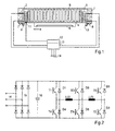
- Fig. 1 shows the necessary parts for explaining the invention of a friction welding device.
- two electromagnets 2, 3 are arranged, which draw a swing frame 4 according to the energization respectively in their direction - in the case of the electromagnet 2 in the direction of the arrow s.
- the swing frame 4 is mounted on the head bridge 1 by means of a spring 5 vibratory.
- the swing frame carries a workpiece holder 6, which is designed depending on the part to be connected and accordingly can be replaced.
- the swing frame 4, the spring 5 and the workpiece holder 6 are also called oscillators for short.
- the head bridge on supports 9, 10 are mounted, which are part of a machine that carries, inter alia, in a manner not shown a receptacle for the other part to be connected, which is pressed for the welding operation to the workpiece holder 6 ,
- a displacement sensor 11 measures the respective position of the oscillating frame and forwards it as a corresponding electrical signal to a controller 12.
- Output signals of the controller 12 are fed to a power output stage 13, which is connected at three-phase to the power grid.
- FIG. 2 An example of the power output stage 13 is in Fig. 2 shown in more detail.
- the supplied at 14 mains voltage is rectified by a three-phase rectifier 15.
- a capacitor 16 serves to smooth the DC voltage and to buffer the pulsating load.
- the arrangement shown is produced in large numbers as a three-phase converter.
- An included in Fig. 2 not shown processor need only be programmed to implement the invention in an appropriate manner.
- the power output stage is provided by two series-connected power transistors T1, T4, T3, T6; T5, T2 formed, each having a freewheeling diode D1, D4; D3, D6; D5, D2 is connected in parallel.
- the middle bridge branch T3, T6 is controlled in each case in dependence on the direction of movement of the vibrator with the oscillation frequency.
- one of the transistors T5 or T4 is in each case connected to a higher one Frequency pulse width modulated or driven according to a tolerance band control of the current.
- the diodes D3 and D6 of the middle bridge branch and the diodes D2 and D1 serve as freewheeling diodes. Details of the conductive phases of the semiconductor switches will be discussed later Fig. 4 explained.
- the diagram a shows the time course of the path s of the oscillator, the diagrams d and c the course of the currents iL (2) and iL (3) of the two electromagnets 2, 3 ( Fig. 1 ).
- the electromagnets are energized in such a way that the oscillation is supported.
- the third half-wave for example, at time t1, a command for braking takes place, whereupon in the following half-wave a waiting pause is formed in that none of the electromagnets is energized.
- each of the electromagnet is energized, which slows the oscillation, so that their amplitude decreases.
- the current is switched off in order to avoid reverse phase excitation.
- Fig. 4 represents a timing diagram of the current i, as well as hatched areas the respective conductive phases of the semiconductor switches.
- the semiconductor switch T6 is largely conductive during the corresponding half-wave of the movement phase.
- the semiconductor switch T5 is clocked, the duty cycle is regulated according to the predetermined oscillation amplitude.
- the current flows through the energy stored in the electromagnet in Freewheel via the diode D2 and the semiconductor switch T6.
- the current flows through the diodes D2 and D3 back into the capacitor and sounds because of its voltage very quickly.
- the electromagnet 3 is energized.
- the conductive phases of the semiconductor switches T3 and T4 and of the diodes D6 and D1 correspond to the conducting phases of the semiconductor switches T6 and T5 as well as the diodes D3 and D2 in the preceding half-cycle.
Landscapes
- Engineering & Computer Science (AREA)
- Mechanical Engineering (AREA)
- Apparatuses For Generation Of Mechanical Vibrations (AREA)
- Pressure Welding/Diffusion-Bonding (AREA)
- Lining Or Joining Of Plastics Or The Like (AREA)
- Arc Welding Control (AREA)
- General Induction Heating (AREA)
Claims (9)
- Procédé de soudage par friction avec lequel l'une des pièces à assembler est mise en oscillation à l'aide d'un oscillateur électromagnétique (4, 5, 6) et un amorçage d'oscillation, commandé par un détecteur de course (11), est effectué par l'application alternée de deux électroaimants (2, 3) agissant en opposition, caractérisé en ce que l'oscillateur (4, 5, 6) est freiné électriquement après un amorçage régulé de l'oscillation et un temps d'oscillation pouvant être prédéfini, qu'en fonction du sens du mouvement correspondant de l'oscillateur (4, 5, 6), un électroaimant (2, 3) qui assiste le mouvement est alimenté électriquement lors de l'amorçage de l'oscillation et un électroaimant (2, 3) qui ralentit le mouvement correspondant est alimenté électriquement lors du freinage et que le courant est déconnecté pendant le freinage lorsqu'une amplitude d'oscillation prédéfinie est atteinte.
- Procédé selon la revendication 1, caractérisé en ce que l'amorçage de l'oscillation et le freinage sont respectivement plus courts que 80 ms.
- Arrangement de soudage par friction avec lequel il est prévu un oscillateur (4, 5, 6) avec lequel l'une des pièces à assembler est mise en oscillation et lequel est entraîné par des électroaimants (2, 3) agissant en opposition, une sortie d'un détecteur de course (11) qui enregistre la position correspondante de l'oscillateur (4, 5, 6) étant reliée avec une entrée d'un régulateur (12) dont la sortie est reliée aux entrées d'un étage final de puissance (13) pour les électroaimants (2, 3), caractérisé en ce que le régulateur (12) est configuré de telle sorte qu'il commande l'étage final de puissance (13) de sorte qu'en fonction du sens du mouvement correspondant de l'oscillateur (4, 5, 6), un électroaimant (2, 3) qui assiste le mouvement est alimenté électriquement, qu'un électroaimant (2, 3) qui ralentit le mouvement correspondant est alimenté électriquement pour le freinage et que le courant est déconnecté pendant le freinage lorsqu'une amplitude d'oscillation prédéfinie est atteinte.
- Arrangement selon la revendication 3, caractérisé en ce que l'étage final de puissance (13) est formé par une première branche de pont constituée de deux commutateurs à semiconducteur (T3, T6) branchés en série en parallèle desquels sont branchées des diodes de roue libre (D3, D6) et par deux branches de pont supplémentaires constituées respectivement d'un circuit série incluant un commutateur à semiconducteur (T1, T2) et une diode (D4, D5), que les bobines des électroaimants (2, 3) sont branchées d'un côté entre le point de connexion des commutateurs à semiconducteur (T3, T6) de la première branche de pont et à chaque fois un point de connexion des autres branches de pont de l'autre côté, que les commutateurs à semiconducteur (T3, T6) de la première branche de pont sont commandés avec la fréquence d'oscillation et les commutateurs à semiconducteur (T1, T2) des autres branches du pont sont modulés en largeur d'impulsion ou régulés en bande de tolérance, des fréquences supérieures à la fréquence d'oscillation pouvant être obtenues en fonction de l'état de la régulation.
- Arrangement selon la revendication 4, caractérisé en ce que les diodes (D4, D5) des commutateurs à semiconducteur (T4, T5) sont formées par des diodes de roue libre (D4, D5) branchées en parallèle.
- Arrangement selon la revendication 5, caractérisé en ce que le courant à travers les électroaimants (2, 3) est permuté sur les branches de pont supplémentaires d'un cycle de travail à l'autre.
- Arrangement selon l'une des revendications 3 à 6, caractérisé en ce que les moyens pour former un signal de déclenchement destiné à faire passer le courant à travers les électroaimants (2, 3) respectifs sont configurés de telle sorte que le signal de déclenchement se produit à une part pouvant être prédéfinie, de préférence un quart de la durée d'une oscillation après un passage par zéro de l'oscillation.
- Arrangement selon l'une des revendications 3 à 7, caractérisé en ce que le régulateur (12) présente une part intégrale qui se voit dotée au début d'une valeur très élevée.
- Arrangement selon l'une des revendications 3 à 8, caractérisé en ce que l'oscillateur (4, 5, 6) ainsi que son support antivibratoire (5) et l'attachement d'outil (6), le détecteur de course (11), le régulateur (12), l'étage final de puissance (13) et les électroaimants (2, 3) forment un circuit oscillant dont la fréquence de résonance est pour l'essentiel déterminée par la fréquence propre de l'oscillateur (4, 5, 6), y compris son support antivibratoire (5) et l'attachement d'outil (6).
Applications Claiming Priority (2)
| Application Number | Priority Date | Filing Date | Title |
|---|---|---|---|
| DE2003147345 DE10347345B4 (de) | 2003-10-11 | 2003-10-11 | Verfahren und Anordnung zum Reibungsschweißen |
| PCT/DE2004/002252 WO2005035227A1 (fr) | 2003-10-11 | 2004-10-11 | Procede et dispositif de soudage par fiction |
Publications (2)
| Publication Number | Publication Date |
|---|---|
| EP1670632A1 EP1670632A1 (fr) | 2006-06-21 |
| EP1670632B1 true EP1670632B1 (fr) | 2010-05-05 |
Family
ID=34428327
Family Applications (1)
| Application Number | Title | Priority Date | Filing Date |
|---|---|---|---|
| EP20040789958 Expired - Lifetime EP1670632B1 (fr) | 2003-10-11 | 2004-10-11 | Procede et dispositif de soudage par fiction |
Country Status (11)
| Country | Link |
|---|---|
| US (1) | US20070131735A1 (fr) |
| EP (1) | EP1670632B1 (fr) |
| JP (1) | JP2007508158A (fr) |
| KR (1) | KR20060120088A (fr) |
| CN (1) | CN1867445A (fr) |
| AT (1) | ATE466719T1 (fr) |
| BR (1) | BRPI0415258A (fr) |
| DE (2) | DE10347345B4 (fr) |
| ES (1) | ES2345890T3 (fr) |
| PT (1) | PT1670632E (fr) |
| WO (1) | WO2005035227A1 (fr) |
Families Citing this family (10)
| Publication number | Priority date | Publication date | Assignee | Title |
|---|---|---|---|---|
| DE10347984A1 (de) * | 2003-10-15 | 2005-05-19 | Branson Ultraschall Niederlassung Der Emerson Technologies Gmbh & Co | Verfahren zum Vibrationsschweißen mit verkürtzter Ausschwingzeit |
| CN100368139C (zh) * | 2006-01-26 | 2008-02-13 | 中南大学 | 超声搅拌焊接方法及其装置 |
| CN100448590C (zh) * | 2006-12-29 | 2009-01-07 | 西北工业大学 | 线性摩擦焊机摩擦压力加载机构 |
| US20120006810A1 (en) * | 2010-07-09 | 2012-01-12 | GM Global Technology Operations LLC | Induction heating-assisted vibration welding method and apparatus |
| US8245748B2 (en) * | 2010-07-14 | 2012-08-21 | Dukane Corporation | Vibration welding system |
| CN102649313A (zh) * | 2012-03-30 | 2012-08-29 | 苏州凯尔博精密机械有限公司 | 一种用于振动摩擦焊接机的振动头 |
| DE102013102322B4 (de) | 2013-03-08 | 2018-05-30 | Osram Opto Semiconductors Gmbh | Verfahren und Vorrichtung zur Vermessung und Optimierung einer optoelektronischen Komponente |
| DE102015122314B3 (de) * | 2015-12-18 | 2016-12-15 | Pewag Austria Gmbh | Linearreibschweißmaschine |
| CN110170737A (zh) * | 2019-05-30 | 2019-08-27 | 苏州英威腾电力电子有限公司 | 一种振动摩擦焊方法、系统及相关装置 |
| CN113478065A (zh) * | 2021-06-30 | 2021-10-08 | 苏州英威腾电力电子有限公司 | 复用h桥电路的控制方法、控制电路以及摩擦焊装置 |
Family Cites Families (7)
| Publication number | Priority date | Publication date | Assignee | Title |
|---|---|---|---|---|
| US4715523A (en) * | 1984-11-12 | 1987-12-29 | Lebedev Vladimir K | Electromagnetic power drive for a friction welding machine |
| DD288338A5 (de) * | 1989-10-06 | 1991-03-28 | Ingenieurhochschule Koethen,De | Vorrichtung zur steuerung der reibzeit von reibschweissmaschinen |
| DE4001367A1 (de) * | 1990-01-18 | 1991-09-19 | Branson Ultraschall | Vorrichtung zum einstellen eines maschinenparameters beim reibungsschweissen |
| DE19512820B4 (de) * | 1995-04-05 | 2005-11-03 | Branson Ultraschall Niederlassung Der Emerson Technologies Gmbh & Co | Verfahren und Vorrichtung zum Einstellen der Arbeitsfrequenz eines Orbitalvibrationsschweißsystems |
| US6404154B2 (en) * | 1998-06-02 | 2002-06-11 | Emerson Electric Co. | Force control system |
| US6091215A (en) * | 1998-06-02 | 2000-07-18 | Switched Reluctance Drives Limited | Trajectory controller |
| WO2002076737A1 (fr) * | 2001-03-21 | 2002-10-03 | Forward Technology Industries, Inc. | Procede et appareil pour soudage par vibration lineaire |
-
2003
- 2003-10-11 DE DE2003147345 patent/DE10347345B4/de not_active Revoked
-
2004
- 2004-10-11 ES ES04789958T patent/ES2345890T3/es not_active Expired - Lifetime
- 2004-10-11 DE DE200450011139 patent/DE502004011139D1/de not_active Expired - Lifetime
- 2004-10-11 CN CNA2004800296931A patent/CN1867445A/zh active Pending
- 2004-10-11 BR BRPI0415258 patent/BRPI0415258A/pt not_active IP Right Cessation
- 2004-10-11 JP JP2006529631A patent/JP2007508158A/ja active Pending
- 2004-10-11 AT AT04789958T patent/ATE466719T1/de not_active IP Right Cessation
- 2004-10-11 WO PCT/DE2004/002252 patent/WO2005035227A1/fr not_active Ceased
- 2004-10-11 EP EP20040789958 patent/EP1670632B1/fr not_active Expired - Lifetime
- 2004-10-11 PT PT04789958T patent/PT1670632E/pt unknown
- 2004-10-11 KR KR1020067008994A patent/KR20060120088A/ko not_active Withdrawn
- 2004-10-11 US US10/573,927 patent/US20070131735A1/en not_active Abandoned
Also Published As
| Publication number | Publication date |
|---|---|
| CN1867445A (zh) | 2006-11-22 |
| ATE466719T1 (de) | 2010-05-15 |
| WO2005035227A1 (fr) | 2005-04-21 |
| DE10347345B4 (de) | 2006-06-14 |
| DE502004011139D1 (fr) | 2010-06-17 |
| BRPI0415258A (pt) | 2006-12-12 |
| PT1670632E (pt) | 2010-07-28 |
| ES2345890T3 (es) | 2010-10-05 |
| DE10347345A1 (de) | 2005-05-12 |
| EP1670632A1 (fr) | 2006-06-21 |
| US20070131735A1 (en) | 2007-06-14 |
| KR20060120088A (ko) | 2006-11-24 |
| JP2007508158A (ja) | 2007-04-05 |
Similar Documents
| Publication | Publication Date | Title |
|---|---|---|
| DE69937587T2 (de) | Aktuator-Treiberschaltkreis | |
| DE3688115T2 (de) | Induktionsmagnetfeldgenerator. | |
| DE69216577T2 (de) | Induktionsheizgeraet | |
| EP1935213B1 (fr) | Procede pour faire fonctionner un systeme de chauffage par induction | |
| EP1251991A1 (fr) | Procede pour la regulation et/ou la commande d'une source de courant de soudage grace a un circuit a resonance | |
| DE10347345B4 (de) | Verfahren und Anordnung zum Reibungsschweißen | |
| DE102009027688A1 (de) | Handgehaltene Elektrowerkzeugmaschine | |
| DE3642634A1 (de) | Eintakt-gleichstromumrichter mit verlustloser umschaltung | |
| DE102007040550A1 (de) | Steuerungsschema für einen Gleichstrom/Wechselstrom-Direktumrichter | |
| EP0136968A2 (fr) | Dispositif de commande pour l'alimentation d'un électro-aimant par un courant d'appel suivi d'un courant de maintien | |
| DE3109073A1 (de) | Stromversorgungsvorrichtung | |
| DE3639075A1 (de) | Einrichtung zum steuern einer hochfrequenz-energieversorgung | |
| DE2417443B2 (de) | Elektrischer Schwingverdichter fur Kältemaschinen | |
| DE69730505T2 (de) | Betätigungs- und regelverfahren und vorrichtung, insbesondere für synchrone, permanentmagnet-motoren | |
| DE3139523C2 (de) | Regeleinrichtung für einen Schwingankermotor | |
| DE3739047C2 (fr) | ||
| DE102004010331B4 (de) | Verfahren und Vorrichtung zum Erzeugen eines elektrischen Heizstroms, insbesondere zum induktiven Erwärmen eines Werkstücks | |
| EP1168626B1 (fr) | Méthode de réduction des temps d' établissement et de montée dans des circuits oscillants | |
| DE2250889C2 (de) | Elektromagnetischer Vibrator | |
| EP1103350B1 (fr) | Machine-outil avec électro-aimant pour la fixation à une pièce ferromagnétique | |
| DE3709250A1 (de) | Wechselrichter zur speisung eines verbrauchers mit einer induktiven komponente | |
| DE2347935B2 (de) | Vorrichtung zum Erzeugen von Zündsignalen für einen steuerbaren Gleichrichter | |
| DE2016198A1 (de) | Schaltungsanordnung zur Steuerung von elektrischen Schrittmotoren bzw Schritt magnetanordnungen | |
| DE1538042C3 (de) | Schaltungsanordnung zur Umwandlung einer Wechselspannung in eine höherfrequente Wechselspannung | |
| DE4330805A1 (de) | Wechselstromquelle für Lichtbogenschweißprozesse |
Legal Events
| Date | Code | Title | Description |
|---|---|---|---|
| PUAI | Public reference made under article 153(3) epc to a published international application that has entered the european phase |
Free format text: ORIGINAL CODE: 0009012 |
|
| 17P | Request for examination filed |
Effective date: 20060112 |
|
| AK | Designated contracting states |
Kind code of ref document: A1 Designated state(s): AT BE BG CH CY CZ DE DK EE ES FI FR GB GR HU IE IT LI LU MC NL PL PT RO SE SI SK TR |
|
| DAX | Request for extension of the european patent (deleted) | ||
| 17Q | First examination report despatched |
Effective date: 20080331 |
|
| GRAP | Despatch of communication of intention to grant a patent |
Free format text: ORIGINAL CODE: EPIDOSNIGR1 |
|
| GRAS | Grant fee paid |
Free format text: ORIGINAL CODE: EPIDOSNIGR3 |
|
| GRAA | (expected) grant |
Free format text: ORIGINAL CODE: 0009210 |
|
| AK | Designated contracting states |
Kind code of ref document: B1 Designated state(s): AT BE BG CH CY CZ DE DK EE ES FI FR GB GR HU IE IT LI LU MC NL PL PT RO SE SI SK TR |
|
| REG | Reference to a national code |
Ref country code: GB Ref legal event code: FG4D Free format text: NOT ENGLISH |
|
| REG | Reference to a national code |
Ref country code: CH Ref legal event code: EP |
|
| REG | Reference to a national code |
Ref country code: IE Ref legal event code: FG4D Free format text: LANGUAGE OF EP DOCUMENT: GERMAN |
|
| REF | Corresponds to: |
Ref document number: 502004011139 Country of ref document: DE Date of ref document: 20100617 Kind code of ref document: P |
|
| RAP2 | Party data changed (patent owner data changed or rights of a patent transferred) |
Owner name: KLN ULTRASCHALL AG |
|
| REG | Reference to a national code |
Ref country code: PT Ref legal event code: SC4A Free format text: AVAILABILITY OF NATIONAL TRANSLATION Effective date: 20100721 |
|
| REG | Reference to a national code |
Ref country code: NL Ref legal event code: VDEP Effective date: 20100505 |
|
| REG | Reference to a national code |
Ref country code: ES Ref legal event code: FG2A Ref document number: 2345890 Country of ref document: ES Kind code of ref document: T3 |
|
| PG25 | Lapsed in a contracting state [announced via postgrant information from national office to epo] |
Ref country code: SE Free format text: LAPSE BECAUSE OF FAILURE TO SUBMIT A TRANSLATION OF THE DESCRIPTION OR TO PAY THE FEE WITHIN THE PRESCRIBED TIME-LIMIT Effective date: 20100505 Ref country code: NL Free format text: LAPSE BECAUSE OF FAILURE TO SUBMIT A TRANSLATION OF THE DESCRIPTION OR TO PAY THE FEE WITHIN THE PRESCRIBED TIME-LIMIT Effective date: 20100505 |
|
| PG25 | Lapsed in a contracting state [announced via postgrant information from national office to epo] |
Ref country code: FI Free format text: LAPSE BECAUSE OF FAILURE TO SUBMIT A TRANSLATION OF THE DESCRIPTION OR TO PAY THE FEE WITHIN THE PRESCRIBED TIME-LIMIT Effective date: 20100505 Ref country code: SI Free format text: LAPSE BECAUSE OF FAILURE TO SUBMIT A TRANSLATION OF THE DESCRIPTION OR TO PAY THE FEE WITHIN THE PRESCRIBED TIME-LIMIT Effective date: 20100505 |
|
| REG | Reference to a national code |
Ref country code: SK Ref legal event code: T3 Ref document number: E 7933 Country of ref document: SK |
|
| REG | Reference to a national code |
Ref country code: IE Ref legal event code: FD4D |
|
| PG25 | Lapsed in a contracting state [announced via postgrant information from national office to epo] |
Ref country code: CY Free format text: LAPSE BECAUSE OF FAILURE TO SUBMIT A TRANSLATION OF THE DESCRIPTION OR TO PAY THE FEE WITHIN THE PRESCRIBED TIME-LIMIT Effective date: 20100505 Ref country code: GR Free format text: LAPSE BECAUSE OF FAILURE TO SUBMIT A TRANSLATION OF THE DESCRIPTION OR TO PAY THE FEE WITHIN THE PRESCRIBED TIME-LIMIT Effective date: 20100806 Ref country code: PL Free format text: LAPSE BECAUSE OF FAILURE TO SUBMIT A TRANSLATION OF THE DESCRIPTION OR TO PAY THE FEE WITHIN THE PRESCRIBED TIME-LIMIT Effective date: 20100505 |
|
| PG25 | Lapsed in a contracting state [announced via postgrant information from national office to epo] |
Ref country code: DK Free format text: LAPSE BECAUSE OF FAILURE TO SUBMIT A TRANSLATION OF THE DESCRIPTION OR TO PAY THE FEE WITHIN THE PRESCRIBED TIME-LIMIT Effective date: 20100505 Ref country code: EE Free format text: LAPSE BECAUSE OF FAILURE TO SUBMIT A TRANSLATION OF THE DESCRIPTION OR TO PAY THE FEE WITHIN THE PRESCRIBED TIME-LIMIT Effective date: 20100505 Ref country code: IE Free format text: LAPSE BECAUSE OF FAILURE TO SUBMIT A TRANSLATION OF THE DESCRIPTION OR TO PAY THE FEE WITHIN THE PRESCRIBED TIME-LIMIT Effective date: 20100505 |
|
| PLBI | Opposition filed |
Free format text: ORIGINAL CODE: 0009260 |
|
| PG25 | Lapsed in a contracting state [announced via postgrant information from national office to epo] |
Ref country code: RO Free format text: LAPSE BECAUSE OF FAILURE TO SUBMIT A TRANSLATION OF THE DESCRIPTION OR TO PAY THE FEE WITHIN THE PRESCRIBED TIME-LIMIT Effective date: 20100505 Ref country code: CZ Free format text: LAPSE BECAUSE OF FAILURE TO SUBMIT A TRANSLATION OF THE DESCRIPTION OR TO PAY THE FEE WITHIN THE PRESCRIBED TIME-LIMIT Effective date: 20100505 |
|
| 26 | Opposition filed |
Opponent name: BRANSON ULTRASCHALL NIEDERLASSUNG DER EMERSON TECH Effective date: 20110207 |
|
| PLAX | Notice of opposition and request to file observation + time limit sent |
Free format text: ORIGINAL CODE: EPIDOSNOBS2 |
|
| REG | Reference to a national code |
Ref country code: DE Ref legal event code: R026 Ref document number: 502004011139 Country of ref document: DE Effective date: 20110207 |
|
| BERE | Be: lapsed |
Owner name: KLN ULTRASCHALL G.M.B.H. Effective date: 20101031 |
|
| PG25 | Lapsed in a contracting state [announced via postgrant information from national office to epo] |
Ref country code: MC Free format text: LAPSE BECAUSE OF NON-PAYMENT OF DUE FEES Effective date: 20101031 |
|
| REG | Reference to a national code |
Ref country code: CH Ref legal event code: PL |
|
| GBPC | Gb: european patent ceased through non-payment of renewal fee |
Effective date: 20101011 |
|
| PLBB | Reply of patent proprietor to notice(s) of opposition received |
Free format text: ORIGINAL CODE: EPIDOSNOBS3 |
|
| PG25 | Lapsed in a contracting state [announced via postgrant information from national office to epo] |
Ref country code: LI Free format text: LAPSE BECAUSE OF NON-PAYMENT OF DUE FEES Effective date: 20101031 Ref country code: CH Free format text: LAPSE BECAUSE OF NON-PAYMENT OF DUE FEES Effective date: 20101031 |
|
| PG25 | Lapsed in a contracting state [announced via postgrant information from national office to epo] |
Ref country code: BE Free format text: LAPSE BECAUSE OF NON-PAYMENT OF DUE FEES Effective date: 20101031 Ref country code: GB Free format text: LAPSE BECAUSE OF NON-PAYMENT OF DUE FEES Effective date: 20101011 |
|
| REG | Reference to a national code |
Ref country code: AT Ref legal event code: MM01 Ref document number: 466719 Country of ref document: AT Kind code of ref document: T Effective date: 20101011 |
|
| PG25 | Lapsed in a contracting state [announced via postgrant information from national office to epo] |
Ref country code: AT Free format text: LAPSE BECAUSE OF NON-PAYMENT OF DUE FEES Effective date: 20101011 |
|
| PLCK | Communication despatched that opposition was rejected |
Free format text: ORIGINAL CODE: EPIDOSNREJ1 |
|
| APAH | Appeal reference modified |
Free format text: ORIGINAL CODE: EPIDOSCREFNO |
|
| APBM | Appeal reference recorded |
Free format text: ORIGINAL CODE: EPIDOSNREFNO |
|
| APBP | Date of receipt of notice of appeal recorded |
Free format text: ORIGINAL CODE: EPIDOSNNOA2O |
|
| PG25 | Lapsed in a contracting state [announced via postgrant information from national office to epo] |
Ref country code: LU Free format text: LAPSE BECAUSE OF NON-PAYMENT OF DUE FEES Effective date: 20101011 Ref country code: HU Free format text: LAPSE BECAUSE OF FAILURE TO SUBMIT A TRANSLATION OF THE DESCRIPTION OR TO PAY THE FEE WITHIN THE PRESCRIBED TIME-LIMIT Effective date: 20101106 Ref country code: BG Free format text: LAPSE BECAUSE OF FAILURE TO SUBMIT A TRANSLATION OF THE DESCRIPTION OR TO PAY THE FEE WITHIN THE PRESCRIBED TIME-LIMIT Effective date: 20100505 |
|
| APBQ | Date of receipt of statement of grounds of appeal recorded |
Free format text: ORIGINAL CODE: EPIDOSNNOA3O |
|
| PG25 | Lapsed in a contracting state [announced via postgrant information from national office to epo] |
Ref country code: TR Free format text: LAPSE BECAUSE OF FAILURE TO SUBMIT A TRANSLATION OF THE DESCRIPTION OR TO PAY THE FEE WITHIN THE PRESCRIBED TIME-LIMIT Effective date: 20100505 |
|
| PG25 | Lapsed in a contracting state [announced via postgrant information from national office to epo] |
Ref country code: BG Free format text: LAPSE BECAUSE OF FAILURE TO SUBMIT A TRANSLATION OF THE DESCRIPTION OR TO PAY THE FEE WITHIN THE PRESCRIBED TIME-LIMIT Effective date: 20100805 |
|
| PLAB | Opposition data, opponent's data or that of the opponent's representative modified |
Free format text: ORIGINAL CODE: 0009299OPPO |
|
| R26 | Opposition filed (corrected) |
Opponent name: BRANSON ULTRASCHALL, NIEDERLASSUNG DER EMERSON TEC Effective date: 20110207 |
|
| REG | Reference to a national code |
Ref country code: FR Ref legal event code: PLFP Year of fee payment: 12 |
|
| REG | Reference to a national code |
Ref country code: DE Ref legal event code: R100 Ref document number: 502004011139 Country of ref document: DE |
|
| APBU | Appeal procedure closed |
Free format text: ORIGINAL CODE: EPIDOSNNOA9O |
|
| REG | Reference to a national code |
Ref country code: FR Ref legal event code: PLFP Year of fee payment: 13 |
|
| REG | Reference to a national code |
Ref country code: FR Ref legal event code: PLFP Year of fee payment: 14 |
|
| PLBN | Opposition rejected |
Free format text: ORIGINAL CODE: 0009273 |
|
| STAA | Information on the status of an ep patent application or granted ep patent |
Free format text: STATUS: OPPOSITION REJECTED |
|
| 27O | Opposition rejected |
Effective date: 20160930 |
|
| REG | Reference to a national code |
Ref country code: FR Ref legal event code: PLFP Year of fee payment: 15 |
|
| PGFP | Annual fee paid to national office [announced via postgrant information from national office to epo] |
Ref country code: SK Payment date: 20231002 Year of fee payment: 20 Ref country code: PT Payment date: 20230928 Year of fee payment: 20 |
|
| PGFP | Annual fee paid to national office [announced via postgrant information from national office to epo] |
Ref country code: ES Payment date: 20231117 Year of fee payment: 20 |
|
| PGFP | Annual fee paid to national office [announced via postgrant information from national office to epo] |
Ref country code: IT Payment date: 20231031 Year of fee payment: 20 Ref country code: FR Payment date: 20231023 Year of fee payment: 20 Ref country code: DE Payment date: 20230808 Year of fee payment: 20 |
|
| REG | Reference to a national code |
Ref country code: DE Ref legal event code: R071 Ref document number: 502004011139 Country of ref document: DE |
|
| REG | Reference to a national code |
Ref country code: ES Ref legal event code: FD2A Effective date: 20241025 |
|
| REG | Reference to a national code |
Ref country code: SK Ref legal event code: MK4A Ref document number: E 7933 Country of ref document: SK Expiry date: 20241011 |
|
| PG25 | Lapsed in a contracting state [announced via postgrant information from national office to epo] |
Ref country code: PT Free format text: LAPSE BECAUSE OF EXPIRATION OF PROTECTION Effective date: 20241022 |
|
| PG25 | Lapsed in a contracting state [announced via postgrant information from national office to epo] |
Ref country code: PT Free format text: LAPSE BECAUSE OF EXPIRATION OF PROTECTION Effective date: 20241022 |
|
| PG25 | Lapsed in a contracting state [announced via postgrant information from national office to epo] |
Ref country code: SK Free format text: LAPSE BECAUSE OF EXPIRATION OF PROTECTION Effective date: 20241011 |
|
| PG25 | Lapsed in a contracting state [announced via postgrant information from national office to epo] |
Ref country code: ES Free format text: LAPSE BECAUSE OF EXPIRATION OF PROTECTION Effective date: 20241012 |
|
| PG25 | Lapsed in a contracting state [announced via postgrant information from national office to epo] |
Ref country code: SK Free format text: LAPSE BECAUSE OF EXPIRATION OF PROTECTION Effective date: 20241011 Ref country code: ES Free format text: LAPSE BECAUSE OF EXPIRATION OF PROTECTION Effective date: 20241012 |