EP1670699B1 - Sprühkopf für fliessfähige medien und verfahren zum herstellen eines derartigen kopfes - Google Patents
Sprühkopf für fliessfähige medien und verfahren zum herstellen eines derartigen kopfes Download PDFInfo
- Publication number
- EP1670699B1 EP1670699B1 EP04805728.5A EP04805728A EP1670699B1 EP 1670699 B1 EP1670699 B1 EP 1670699B1 EP 04805728 A EP04805728 A EP 04805728A EP 1670699 B1 EP1670699 B1 EP 1670699B1
- Authority
- EP
- European Patent Office
- Prior art keywords
- nozzle
- cover
- dispenser
- head according
- overcap
- Prior art date
- Legal status (The legal status is an assumption and is not a legal conclusion. Google has not performed a legal analysis and makes no representation as to the accuracy of the status listed.)
- Expired - Lifetime
Links
Images


Classifications
-
- B—PERFORMING OPERATIONS; TRANSPORTING
- B65—CONVEYING; PACKING; STORING; HANDLING THIN OR FILAMENTARY MATERIAL
- B65D—CONTAINERS FOR STORAGE OR TRANSPORT OF ARTICLES OR MATERIALS, e.g. BAGS, BARRELS, BOTTLES, BOXES, CANS, CARTONS, CRATES, DRUMS, JARS, TANKS, HOPPERS, FORWARDING CONTAINERS; ACCESSORIES, CLOSURES, OR FITTINGS THEREFOR; PACKAGING ELEMENTS; PACKAGES
- B65D83/00—Containers or packages with special means for dispensing contents
- B65D83/14—Containers for dispensing liquid or semi-liquid contents by internal gaseous pressure, i.e. aerosol containers comprising propellant
- B65D83/16—Actuating means
- B65D83/20—Actuator caps
-
- B—PERFORMING OPERATIONS; TRANSPORTING
- B05—SPRAYING OR ATOMISING IN GENERAL; APPLYING FLUENT MATERIALS TO SURFACES, IN GENERAL
- B05B—SPRAYING APPARATUS; ATOMISING APPARATUS; NOZZLES
- B05B1/00—Nozzles, spray heads or other outlets, with or without auxiliary devices such as valves, heating means
- B05B1/34—Nozzles, spray heads or other outlets, with or without auxiliary devices such as valves, heating means designed to influence the nature of flow of the liquid or other fluent material, e.g. to produce swirl
- B05B1/3405—Nozzles, spray heads or other outlets, with or without auxiliary devices such as valves, heating means designed to influence the nature of flow of the liquid or other fluent material, e.g. to produce swirl to produce swirl
- B05B1/341—Nozzles, spray heads or other outlets, with or without auxiliary devices such as valves, heating means designed to influence the nature of flow of the liquid or other fluent material, e.g. to produce swirl to produce swirl before discharging the liquid or other fluent material, e.g. in a swirl chamber upstream the spray outlet
- B05B1/3421—Nozzles, spray heads or other outlets, with or without auxiliary devices such as valves, heating means designed to influence the nature of flow of the liquid or other fluent material, e.g. to produce swirl to produce swirl before discharging the liquid or other fluent material, e.g. in a swirl chamber upstream the spray outlet with channels emerging substantially tangentially in the swirl chamber
- B05B1/3431—Nozzles, spray heads or other outlets, with or without auxiliary devices such as valves, heating means designed to influence the nature of flow of the liquid or other fluent material, e.g. to produce swirl to produce swirl before discharging the liquid or other fluent material, e.g. in a swirl chamber upstream the spray outlet with channels emerging substantially tangentially in the swirl chamber the channels being formed at the interface of cooperating elements, e.g. by means of grooves
- B05B1/3436—Nozzles, spray heads or other outlets, with or without auxiliary devices such as valves, heating means designed to influence the nature of flow of the liquid or other fluent material, e.g. to produce swirl to produce swirl before discharging the liquid or other fluent material, e.g. in a swirl chamber upstream the spray outlet with channels emerging substantially tangentially in the swirl chamber the channels being formed at the interface of cooperating elements, e.g. by means of grooves the interface being a plane perpendicular to the outlet axis
Definitions
- the present invention relates to a fluid dispenser head intended to be associated with or mounted on a fluid dispenser member.
- the invention also relates to a method of manufacturing such a dispensing head.
- the dispensing head comprises within the scope of the present invention a body defining an outlet channel for the fluid, a nozzle defining a dispensing orifice and an overcap mounted on the body so as to mask at least a portion.
- Such a dispensing head can be used in the fields of perfumery, cosmetics or even pharmacy.
- the document FR 2,774,367 discloses such a dispensing head comprising a body, a nozzle, and an overcap.
- the body is fixedly attached inside the overcap.
- the maintenance of the body inside the overcap is ensured by the friction forces between the outer wall of the body and the inner wall of the overcap.
- the overcapsule masks the upper wall and the peripheral wall of the body.
- the nozzle is previously mounted on the body before the engagement of the body in the overcap, or alternatively, the nozzle is inserted into the body once the body is engaged in the overcap.
- the overcap comprises a barrel defining a window at which is positioned the dispensing orifice formed by the nozzle.
- the mounting of the dispensing head is carried out in two separate mounting operations, namely the mounting of the nozzle on the body and mounting the body in the overcap.
- the mounting of the body in the overcapsule requires very low tolerances to ensure a good maintenance of the body in the overcap.
- the engagement of the body in the over-capsule must be able to be carried out with a reasonable bundling force. This is why both the overcap and the body have to be made with great precision, which increases the manufacturing costs. It is the same with regard to the jet and the body.
- the fluid dispensing head of the invention provides that the overcap is overmolded on the body.
- overmoulding it is meant that the body forms a part of the mold of the overcap.
- a portion of the outer surface of the plastic material injected into the mold of the overcap is going to come into direct contact with the body. This contact achieves an adhesion which results in a solid fixation of the over-capsule on the body.
- the over-capsule closely follows all the contours and asperities of the body.
- the body comprises an upper surface and a peripheral surface, the over-capsule is overmolded on the upper surface, and advantageously also on the peripheral surface.
- the overcap comprises a barrel provided with a window for the passage of the nozzle to be mounted on the body by engaging it through the window.
- the dispensing orifice is positioned in the window.
- the dispensing orifice is positioned back from the window substantially at an outer surface of the body.
- the window has a frustoconical shape that flares outwardly.
- the frustoconical surface serves as a diffusion cone that allows the jet of sprayed fluid to be channeled through the dispensing orifice.
- the body comprises a peripheral skirt forming the outer surface peripherally, said skirt being provided with an opening on a receiving housing for the nozzle, said housing advantageously forming a core around which the nozzle is engaged in force.
- an intermediate element is disposed between the body and the overcap, said overcap being made of a material translucent or transparent so that the interlayer is visible through the overcap.
- this intermediate element between the body and the overcap can be implemented without the overcap is overmolded on the body.
- the characteristic related to the intermediate element can therefore be independently protected.
- the nozzle protrudes outwardly from the peripheral surface.
- the dispensing head according to the invention can in particular serve as a pusher.
- the overcap can define a bearing surface for the application of pressure to actuate the dispenser member.
- the invention also defines a method for manufacturing a fluid product dispensing head intended to be associated with a fluid dispenser member, said head comprising a body defining an outlet channel for the fluid product, a nozzle defining a dispensing orifice and an overcap mounted on the body so as to mask at least a portion, said method comprising successively a first overmoulding step of the overcap on the body and a second step of mounting the nozzle on the body.
- the invention may also provide a method for manufacturing a fluid product dispensing head intended to be associated with a fluid dispenser member, said head comprising a body defining an outlet channel for the fluid product, a nozzle defining a dispensing orifice and an overcap mounted on the body so as to mask at least a portion, the method comprising successively a first step of mounting the nozzle on the body and a second step of overmolding the overcap on the body , and possibly on the nozzle.
- an intermediate element may be disposed between the body and the overcap, said overcap being made of a transparent or translucent material. This is valid for both variants of manufacturing processes.
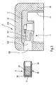
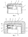
- the dispensing head comprises three constituent elements, namely a body 1, a nozzle 2 or 2 'and an overcap 3. It is however not excluded that the body and the nozzle be made in one piece or in an equivalent manner.
- the body 1 is identical in all the embodiments of the figures. However, one can provide other forms for the body 1. In the case of the figures, it is a body designed to form a pusher-type dispensing head on which is pressed with the help of a finger to actuate the dispensing member which may be a pump or a valve. However, it is conceivable that the body is intended to be associated with a dispensing member (pump or valve) completely disassociated from the actuating pusher. In this case, the body 1 is intended to be fixedly mounted relative to the body of the pump or the valve and the reservoir. Thus, in the figures, the pusher body 1 may be of the standard type made of a molded injected plastic material which is compatible with the fluid product to be dispensed.
- the body comprises an upper plate 11 which defines an outer upper surface 111.
- the body also comprises a peripheral skirt 12 which defines a peripheral outer surface 121.
- the upper surface 111 is connected on its outer peripheral edge advantageously rounded to the substantially cylindrical or perfectly cylindrical peripheral surface 121.
- the plate 11 and the skirt 12 thus define an inverted cup shape.
- the body forms internally below the plate 111 a connecting sleeve 13 and a receiving housing 14.
- the sleeve 13 defines an internal outlet duct 131 through which the fluid product discharged by the pump or valve flows into the housing 14 through a small connecting channel 134.
- the housing 14, more visible on the figure 3 defines an opening 142 at the level of the peripheral skirt 12.
- the housing 14 contains a core 141 integrally formed by the body 1.
- the core defines externally a receiving ring for the nozzle 2 or 2 'as will be seen hereinafter after. This is a quite classic design for a standard push body.
- the nozzle 2 or 2 ' comprises a base sleeve 20 of substantially cylindrical shape and closed at one of its ends by a distribution wall. This distribution wall is traversed by a dispensing orifice 21 which may be of the spray type or not. Part of the bushing 20 defines a fastener ring 24 intended to engage in the annular housing formed around the core 141.
- the nozzle may comprise a filling piece 23. This piece 23 may cooperate with the distribution wall so as to form a swirling system, conventionally constituted by radial swirling channels opening into a chamber of central swirl centered on the dispensing orifice 21.
- the particular design of the nozzle 2 or 2 ' is not critical for the present invention. It is sufficient that the nozzle cooperates with the body to fulfill its function of spraying the fluid product.
- the nozzle protrudes outwardly from the peripheral surface 121 of the body. It can also be said that the dispensing orifice 21 is projected radially outwards with respect to the peripheral surface 121.
- the dispensing orifice 21 is substantially aligned with the peripheral surface 121.
- the nozzle is inscribed in the housing formed by the body.
- Embodiments may also be conceived in which the dispensing orifice is recessed within the housing formed by the body so that the orifice is inwardly offset relative to the peripheral surface 121.
- the nozzle 2 or 2 ' is mounted by lateral or radial engagement in the housing 14 with respect to the X axis shown in FIG. figure 4 .
- the over-capsule 3 is mounted on the body 1 by coming into contact with part or all of the upper surface 111 and the peripheral surface 121. However, the overcap can in some cases come into contact with a part or the entire upper surface 111, leaving the peripheral surface 121 visible or unmasked. The over-capsule 3 thus masks most of the outer surface of the body 1 while leaving however its lower face open and disengaged so as to mount the dispensing head on a dispensing member such as a pump or a valve. Indeed, the connecting sleeve 13 must remain accessible.
- Overcap 3 comprises a bearing wall 31 forming an outer bearing surface 312.
- the overcap 3 comprises a substantially cylindrical peripheral barrel 32 which surrounds the skirt 12 of the body 1.
- the bearing wall 31 comprises an inner surface 311 which comes into intimate contact with the upper surface 111 of the plateau 11.
- the shaft 32 forms an inner surface 321 which advantageously comes into intimate contact with the outer peripheral surface 121 of the skirt 12.
- the hole 32 is also traversed by a window 322 which communicates the outside of the barrel with the inside of the barrel. This window 322 is intended for the passage or reception of the nozzle 2 or 2 ', according to the embodiments, as will be shown below.
- the over-capsule 3 can also come into intimate contact with the nozzle 2 at the level of the window 322, as can be seen in FIG. figure 2 .
- the window 322 can be made with a frustoconical shape 323 which flares outwardly.
- the window 322 must be positioned in line with the housing 14 of the body 1 intended to receive the nozzle 2 or 2 '.
- the over-capsule 3 may be made of an aesthetic plastic material which may possibly be incompatible with the fluid product to be dispensed. It can also be made of transparent material or in a material providing a touch of silky or rubbery feel.
- the over-capsule 3 is overmolded on the body 1, and advantageously also on the nozzle 2. This means that the over-capsule 3 is directly molded on the body and / or the nozzle 2. This technique makes it possible to obtain a contact intimate between the surfaces of the overcap and the body and / or nozzle.
- the nozzle 2 is previously engaged radially in its housing 14 formed by the body 1.
- the dispensing orifice 21 of the nozzle projects outwardly with respect to the skirt 12.
- the overcap 3 is overmolded on the body 1 and on the nozzle 2.
- the overmolding of the overcapsule permanently maintains the nozzle 2 on the body 1.
- the dispensing orifice 21 is located in the window 322 which intimately surrounds the nozzle 2. More specifically, the nozzle 21 is located near the outer surface of the barrel 32 of the overcap 3.
- overcap 3 is first overmolded on the body 1.
- a pin centered on the housing 14 allows the window 322 in the overcap 3 to be made.
- a subsequent mounting operation is to engage the nozzle 2 through the window 322 until it comes into definitive mounting in the housing 14 of the body 1.
- the dispensing head is in the form shown on the figure 2 .
- the nozzle 2 ' is previously mounted on the body 1.
- the dispensing orifice 21 does not project out of the body, but remains aligned with the skirt 12.
- a subsequent molding operation consists of overmolding the overcap 3 on the body 1 with the nozzle 2 'previously mounted.
- a pin centered on the nozzle 2 ' makes it possible to produce a frustoconical window 322 whose frustoconical wall 323 serves as a diffusion cone for the jet of sprayed product.
- the body 1 and the nozzle 2 ' may be identical to those of the figure 4 , that is to say with the nozzle 2 'previously mounted on the body 1.
- an intermediate element 4 is disposed on the upper surface 111 of the body 1.
- This intermediate element 4 can be simply deposited or fixed on the body 1. It can even be overmoulded the body 1 on the intermediate element 4.
- This intermediate element 4 can perform an aesthetic or decorative function.
- the element 4 is represented on the upper surface 111, it can also be imagined that it extends also or only on the peripheral surface 121.
- a subsequent molding operation consists of overmoulding the over-capsule 3 on the body 1 and on the intermediate element 4.
- the intermediate element 4 is thus interposed between the body 1 and the overcap 3.
- the overcap 3 is made of a transparent or translucent material so as to leave the intermediate element 4 visible through the over-capsule 3.
- the over-capsule 3 can be identical to that of the figure 5 that is to say with a frustoconical window 322.
- the interposition of a spacer advantageously aesthetic or decorative element can be implemented with an overcap attached or fixed in any way on the body, without it necessarily being necessary that the overcap 3 is overmolded on the body 1. It is possible to imagine that the over-capsule 3 is only reported in force on the body 1, as the document of the prior art FR 2,774,367 .
- overmolding is an equivalent of the terms "comoulage” or "bi-injection”. It generally means that an element, in this case the overcap, is molded on another element, namely the body and / or the nozzle.
Landscapes
- Chemical & Material Sciences (AREA)
- Dispersion Chemistry (AREA)
- Engineering & Computer Science (AREA)
- Mechanical Engineering (AREA)
- Containers And Packaging Bodies Having A Special Means To Remove Contents (AREA)
- Closures For Containers (AREA)
Claims (14)
- Ausgabekopf für ein fluides Produkt zum Verbinden mit einer Ausgabeeinrichtung für ein fluides Produkt, wobei der Kopf einen Körper (1), der einen Auslasskanal (131) für das fluide Produkt definiert, eine Spritzdüse (2; 2'), die eine Ausgabeöffnung (21) definiert, sowie eine Umhüllung (3) aufweist, die derart auf dem Körper (1) montiert ist, dass sie zumindest einen Teil von diesem verdeckt,
dadurch gekennzeichnet, dass die Umhüllung (3) auf den Körper (1) aufgegossen ist. - Ausgabekopf nach Anspruch 1, wobei der Körper (1) eine obere Fläche (111) und eine Umfangsfläche (121) aufweist und die Umhüllung (3) auf die obere Fläche (111) und vorteilhafterweise auch auf die Umfangsfläche (121) aufgegossen ist.
- Ausgabekopf nach Anspruch 1 oder 2, wobei die Umhüllung (3) auf die Spritzdüse (2) aufgegossen ist, die zuvor auf dem Körper (1) montiert wurde.
- Ausgabekopf nach Anspruch 1 oder 2, wobei die Umhüllung (3) eine mit einem Fenster (322) versehene Hülse (32) für das Hindurchführen der Spritzdüse (2; 2') aufweist, die auf den Körper (1) montiert werden soll, indem sie durch das Fenster (322) eingebunden wird.
- Ausgabekopf nach Anspruch 4, wobei die Ausgabeöffnung (21) in dem Fenster (322) positioniert ist.
- Ausgabekopf nach Anspruch 4, wobei die Ausgabeöffnung (21) im Wesentlichen an einer Außenfläche (121) des Körpers (1) in Bezug auf das Fenster (322) zurückgesetzt ist.
- Ausgabekopf nach Anspruch 6, wobei das Fenster (322) eine kegelstumpfartige Form (323) aufweist, die nach außen aufgeweitet ist.
- Ausgabekopf nach Anspruch 2, wobei der Körper (1) einen Umfangsmantel (12) aufweist, der außen die Umfangsfläche (121) bildet, wobei der Mantel mit einer Öffnung (142) versehen ist, die zu einem Aufnahmesitz (14) für die Spritzdüse weist, wobei der Sitz (14) vorteilhafterweise einen Kern (141) bildet, um welchen die Spritzdüse (2; 2') kraftschlüssig im Eingriff ist.
- Ausgabekopf nach einem der vorhergehenden Ansprüche, wobei ein zwischengeschaltetes Element (4) zwischen dem Körper (1) und der Umhüllung (3) angeordnet ist, wobei die Umhüllung derart aus einem durchscheinenden oder transparenten Material gefertigt ist, dass das zwischengeschaltete Element durch die Umhüllung sichtbar ist.
- Ausgabekopf nach einem der vorhergehenden Ansprüche, wobei die Spritzdüse (2) von der Umfangsfläche (121) nach außen vorsteht.
- Ausgabekopf nach einem der vorhergehenden Ansprüche, wobei die Umhüllung (3) eine Stützfläche (312) definiert, die dazu geeignet ist, einen Druck auszuüben, um die Ausgabeeinrichtung zu betätigen.
- Verfahren zur Herstellung eines Ausgabekopfes für ein fluides Produkt zum Verbinden mit einer Ausgabeeinrichtung für ein fluides Produkt, wobei der Kopf einen Körper (1), der einen Auslasskanal (131) für das fluide Produkt definiert, eine Spritzdüse (2; 2'), die eine Ausgabeöffnung (21) definiert, sowie eine Umhüllung (3) aufweist, die derart auf dem Körper (1) montiert ist, dass zumindest ein Teil von diesem verdeckt wird, wobei das Verfahren nacheinander einen ersten Schritt des Aufgießens der Umhüllung auf den Körper und einen zweiten Schritt des Montierens der Spritzdüse auf dem Körper aufweist.
- Verfahren zur Herstellung eines Ausgabekopfes für ein fluides Produkt zum Verbinden mit einer Ausgabeeinrichtung für ein fluides Produkt, wobei der Kopf einen Körper (1), der einen Auslasskanal (131) für das fluide Produkt definiert, eine Spritzdüse (2; 2'), die eine Ausgabeöffnung (21) definiert, und eine Umhüllung (3) aufweist, die derart auf dem Körper (1) montiert ist, dass zumindest ein Teil von diesem verdeckt ist, wobei das Verfahren nacheinander einen ersten Schritt der Montage der Spritzdüse auf dem Körper und einen zweiten Schritt des Aufgießens der Umhüllung auf den Körper und gegebenenfalls auf die Spritzdüse aufweist.
- Verfahren zur Herstellung nach Anspruch 12 oder 13, wobei ein zwischengeschaltetes Element (4) zwischen dem Körper (1) und der Umhüllung (3) angeordnet ist, wobei die Umhüllung aus einem transparenten oder durchscheinenden Material gefertigt ist.
Applications Claiming Priority (2)
| Application Number | Priority Date | Filing Date | Title |
|---|---|---|---|
| FR0311823A FR2860771B1 (fr) | 2003-10-09 | 2003-10-09 | Tete de distribution de produit fluide et procede de fabrication d'une telle tete |
| PCT/FR2004/050485 WO2005032972A2 (fr) | 2003-10-09 | 2004-10-05 | Tete de distribution de produit fluide et procede de fabrication d'une telle tete. |
Publications (2)
| Publication Number | Publication Date |
|---|---|
| EP1670699A2 EP1670699A2 (de) | 2006-06-21 |
| EP1670699B1 true EP1670699B1 (de) | 2015-04-01 |
Family
ID=34355354
Family Applications (1)
| Application Number | Title | Priority Date | Filing Date |
|---|---|---|---|
| EP04805728.5A Expired - Lifetime EP1670699B1 (de) | 2003-10-09 | 2004-10-05 | Sprühkopf für fliessfähige medien und verfahren zum herstellen eines derartigen kopfes |
Country Status (7)
| Country | Link |
|---|---|
| US (1) | US20070119872A1 (de) |
| EP (1) | EP1670699B1 (de) |
| JP (1) | JP2007509819A (de) |
| CN (1) | CN1882483A (de) |
| BR (1) | BRPI0415118A (de) |
| FR (1) | FR2860771B1 (de) |
| WO (1) | WO2005032972A2 (de) |
Families Citing this family (5)
| Publication number | Priority date | Publication date | Assignee | Title |
|---|---|---|---|---|
| FR2910448B1 (fr) * | 2006-12-22 | 2009-02-20 | Valois Sas | Tete de distribution de produit fluide |
| DE102008024768A1 (de) * | 2008-05-23 | 2009-11-26 | Carl Hoernecke Chem. Fabrik Gmbh & Co. Kg | Reizstoff-Sprühgerät |
| CN102596795A (zh) * | 2009-06-26 | 2012-07-18 | 米德韦斯特瓦科卡尔玛公司 | 泵致动器及其制造方法 |
| US20110139831A1 (en) * | 2009-12-12 | 2011-06-16 | Mike Nelson Rowland | Spray tube with safety feature |
| EP3953051B1 (de) * | 2019-04-10 | 2025-04-23 | Lindal France SAS | Zweiteilige düse für aerosolspender |
Family Cites Families (9)
| Publication number | Priority date | Publication date | Assignee | Title |
|---|---|---|---|---|
| ES2011140A6 (es) * | 1988-10-10 | 1989-12-16 | Monturas Sa | Bomba pulverizadora. |
| DE4041136C2 (de) * | 1990-12-21 | 1994-06-30 | Andris Raimund Gmbh & Co Kg | Dosier- und Spraypumpe zur Abgabe flüssiger, niederviskoser und pastöser Stoffe |
| FR2694510B1 (fr) * | 1992-08-06 | 1994-10-07 | Step Soc Tech Pulverisation | Distributeur pour produits fluides et son procédé de fabrication. |
| FR2750961B1 (fr) * | 1996-07-15 | 1998-09-18 | Aubert Guy | Tete de piston aseptique et interchangeable |
| FR2769008B1 (fr) * | 1997-09-30 | 1999-11-19 | Oreal | Tete de distribution et ensemble de conditionnement et de distribution equipe d'une telle tete |
| FR2774367B1 (fr) | 1998-02-03 | 2000-03-24 | Valois Sa | Tete de distribution de pompe ou de valve |
| FR2816228B3 (fr) * | 2000-11-07 | 2002-10-25 | Valois Sa | Organe de fixation pour fixer une pompe ou une valve sur un col de recipient |
| FR2828821B1 (fr) * | 2001-08-23 | 2004-01-23 | Valois Sa | Tete de distribution pour distributeur de produit fluide |
| US6609666B1 (en) * | 2002-07-24 | 2003-08-26 | William Sydney Blake | Unitary over-mold non-clog system with positive shutoff |
-
2003
- 2003-10-09 FR FR0311823A patent/FR2860771B1/fr not_active Expired - Fee Related
-
2004
- 2004-10-05 US US10/575,095 patent/US20070119872A1/en not_active Abandoned
- 2004-10-05 EP EP04805728.5A patent/EP1670699B1/de not_active Expired - Lifetime
- 2004-10-05 JP JP2006530459A patent/JP2007509819A/ja not_active Withdrawn
- 2004-10-05 CN CNA2004800339481A patent/CN1882483A/zh active Pending
- 2004-10-05 BR BRPI0415118-6A patent/BRPI0415118A/pt not_active IP Right Cessation
- 2004-10-05 WO PCT/FR2004/050485 patent/WO2005032972A2/fr not_active Ceased
Also Published As
| Publication number | Publication date |
|---|---|
| JP2007509819A (ja) | 2007-04-19 |
| FR2860771B1 (fr) | 2006-03-03 |
| WO2005032972A2 (fr) | 2005-04-14 |
| CN1882483A (zh) | 2006-12-20 |
| FR2860771A1 (fr) | 2005-04-15 |
| WO2005032972A3 (fr) | 2005-06-16 |
| EP1670699A2 (de) | 2006-06-21 |
| US20070119872A1 (en) | 2007-05-31 |
| BRPI0415118A (pt) | 2006-11-28 |
Similar Documents
| Publication | Publication Date | Title |
|---|---|---|
| EP2021265B1 (de) | Spenderkopfteil für flüssigprodukt, spender mit derartigem kopfteil und verfahren zur herstellung eines derartigen kopfteils | |
| EP0969933B1 (de) | Vorrichtung zum zerstäuben eines fluids, wie z.b. eine zwei fluiddosen zerstäubende vorrichtung | |
| EP0705143B1 (de) | Sprühdüse und zerstauber mit einer solchen düse | |
| EP0802827B1 (de) | Zerstäubungsdüse | |
| EP1202918A1 (de) | Spender mit gelenkigem spenderkopf | |
| EP1670700B1 (de) | Fluidproduktabgabekopf | |
| FR2923810A1 (fr) | Tete de distribution du type a declenchement par gachette. | |
| EP2608692B1 (de) | Spenderkopf für ein flüssiges produkt | |
| EP1189648B1 (de) | Spender für medien mit einem verbesserten sprühkopf | |
| EP1054820B1 (de) | Pumpen- oder ventil-zerstäubungskopf | |
| FR2860771A1 (fr) | Tete de distribution de produit fluide et procede de fabrication d'une telle tete | |
| EP1427539B1 (de) | Abgabekopf für eine fluidproduktabgabevorrichtung | |
| FR2877324A1 (fr) | Dispositif de distribution comportant un tube d'habillage d'un tube plongeur. | |
| EP0825128B1 (de) | Element zur Befestigung einer Abgabevorrichtung an einem Behälterhals | |
| EP1678056A2 (de) | Fluidproduktabgabevorrichtung | |
| EP3765206A1 (de) | Behälter für fluidpprodukt | |
| EP1024094A1 (de) | Verschliessbaren Zapfkopf | |
| EP1347696B1 (de) | Versiegelte packung für kosmetikprodukt | |
| EP4061538A1 (de) | Verfahren zur herstellung einer verteilungswand | |
| EP1703986A1 (de) | Fluidproduktabgabeglied | |
| FR2824244A1 (fr) | Conditionnement etanche pour produit cosmetique | |
| WO2025083370A1 (fr) | Distributeur de produit fluide | |
| FR3166556A1 (fr) | Pompe réalisable par impression 3D | |
| FR3048914A1 (fr) | Procede de fabrication d'un recipient comprenant une poche souple et une coque rigide | |
| FR2855159A1 (fr) | Tete de distribution montee ou faisant partie d'un organe de distribution de produit fluide |
Legal Events
| Date | Code | Title | Description |
|---|---|---|---|
| PUAI | Public reference made under article 153(3) epc to a published international application that has entered the european phase |
Free format text: ORIGINAL CODE: 0009012 |
|
| 17P | Request for examination filed |
Effective date: 20060425 |
|
| AK | Designated contracting states |
Kind code of ref document: A2 Designated state(s): DE ES FR GB IT |
|
| DAX | Request for extension of the european patent (deleted) | ||
| RBV | Designated contracting states (corrected) |
Designated state(s): DE ES FR GB IT |
|
| RAP1 | Party data changed (applicant data changed or rights of an application transferred) |
Owner name: APTAR FRANCE SAS |
|
| GRAP | Despatch of communication of intention to grant a patent |
Free format text: ORIGINAL CODE: EPIDOSNIGR1 |
|
| INTG | Intention to grant announced |
Effective date: 20140512 |
|
| GRAS | Grant fee paid |
Free format text: ORIGINAL CODE: EPIDOSNIGR3 |
|
| GRAA | (expected) grant |
Free format text: ORIGINAL CODE: 0009210 |
|
| AK | Designated contracting states |
Kind code of ref document: B1 Designated state(s): DE ES FR GB IT |
|
| REG | Reference to a national code |
Ref country code: GB Ref legal event code: FG4D Free format text: NOT ENGLISH |
|
| REG | Reference to a national code |
Ref country code: DE Ref legal event code: R096 Ref document number: 602004046914 Country of ref document: DE Effective date: 20150513 |
|
| REG | Reference to a national code |
Ref country code: FR Ref legal event code: PLFP Year of fee payment: 12 |
|
| PG25 | Lapsed in a contracting state [announced via postgrant information from national office to epo] |
Ref country code: ES Free format text: LAPSE BECAUSE OF FAILURE TO SUBMIT A TRANSLATION OF THE DESCRIPTION OR TO PAY THE FEE WITHIN THE PRESCRIBED TIME-LIMIT Effective date: 20150401 |
|
| REG | Reference to a national code |
Ref country code: DE Ref legal event code: R097 Ref document number: 602004046914 Country of ref document: DE |
|
| PLBE | No opposition filed within time limit |
Free format text: ORIGINAL CODE: 0009261 |
|
| STAA | Information on the status of an ep patent application or granted ep patent |
Free format text: STATUS: NO OPPOSITION FILED WITHIN TIME LIMIT |
|
| 26N | No opposition filed |
Effective date: 20160105 |
|
| PG25 | Lapsed in a contracting state [announced via postgrant information from national office to epo] |
Ref country code: IT Free format text: LAPSE BECAUSE OF FAILURE TO SUBMIT A TRANSLATION OF THE DESCRIPTION OR TO PAY THE FEE WITHIN THE PRESCRIBED TIME-LIMIT Effective date: 20150401 |
|
| REG | Reference to a national code |
Ref country code: DE Ref legal event code: R119 Ref document number: 602004046914 Country of ref document: DE |
|
| GBPC | Gb: european patent ceased through non-payment of renewal fee |
Effective date: 20151005 |
|
| PG25 | Lapsed in a contracting state [announced via postgrant information from national office to epo] |
Ref country code: GB Free format text: LAPSE BECAUSE OF NON-PAYMENT OF DUE FEES Effective date: 20151005 Ref country code: DE Free format text: LAPSE BECAUSE OF NON-PAYMENT OF DUE FEES Effective date: 20160503 |
|
| REG | Reference to a national code |
Ref country code: FR Ref legal event code: PLFP Year of fee payment: 13 |
|
| REG | Reference to a national code |
Ref country code: FR Ref legal event code: PLFP Year of fee payment: 14 |
|
| PGFP | Annual fee paid to national office [announced via postgrant information from national office to epo] |
Ref country code: FR Payment date: 20171027 Year of fee payment: 14 |
|
| PG25 | Lapsed in a contracting state [announced via postgrant information from national office to epo] |
Ref country code: FR Free format text: LAPSE BECAUSE OF NON-PAYMENT OF DUE FEES Effective date: 20181031 |