EP1671341B1 - Dispositif anti-intrusion notamment pour terminal de paiement electronique - Google Patents
Dispositif anti-intrusion notamment pour terminal de paiement electronique Download PDFInfo
- Publication number
- EP1671341B1 EP1671341B1 EP04766864A EP04766864A EP1671341B1 EP 1671341 B1 EP1671341 B1 EP 1671341B1 EP 04766864 A EP04766864 A EP 04766864A EP 04766864 A EP04766864 A EP 04766864A EP 1671341 B1 EP1671341 B1 EP 1671341B1
- Authority
- EP
- European Patent Office
- Prior art keywords
- spring
- housing
- electronic circuit
- intrusion
- button
- Prior art date
- Legal status (The legal status is an assumption and is not a legal conclusion. Google has not performed a legal analysis and makes no representation as to the accuracy of the status listed.)
- Expired - Lifetime
Links
Images



Classifications
-
- G—PHYSICS
- G07—CHECKING-DEVICES
- G07F—COIN-FREED OR LIKE APPARATUS
- G07F7/00—Mechanisms actuated by objects other than coins to free or to actuate vending, hiring, coin or paper currency dispensing or refunding apparatus
- G07F7/08—Mechanisms actuated by objects other than coins to free or to actuate vending, hiring, coin or paper currency dispensing or refunding apparatus by coded identity card or credit card or other personal identification means
- G07F7/10—Mechanisms actuated by objects other than coins to free or to actuate vending, hiring, coin or paper currency dispensing or refunding apparatus by coded identity card or credit card or other personal identification means together with a coded signal, e.g. in the form of personal identification information, like personal identification number [PIN] or biometric data
- G07F7/1008—Active credit-cards provided with means to personalise their use, e.g. with PIN-introduction/comparison system
-
- G—PHYSICS
- G06—COMPUTING OR CALCULATING; COUNTING
- G06F—ELECTRIC DIGITAL DATA PROCESSING
- G06F21/00—Security arrangements for protecting computers, components thereof, programs or data against unauthorised activity
- G06F21/70—Protecting specific internal or peripheral components, in which the protection of a component leads to protection of the entire computer
- G06F21/86—Secure or tamper-resistant housings
-
- G—PHYSICS
- G06—COMPUTING OR CALCULATING; COUNTING
- G06Q—INFORMATION AND COMMUNICATION TECHNOLOGY [ICT] SPECIALLY ADAPTED FOR ADMINISTRATIVE, COMMERCIAL, FINANCIAL, MANAGERIAL OR SUPERVISORY PURPOSES; SYSTEMS OR METHODS SPECIALLY ADAPTED FOR ADMINISTRATIVE, COMMERCIAL, FINANCIAL, MANAGERIAL OR SUPERVISORY PURPOSES, NOT OTHERWISE PROVIDED FOR
- G06Q20/00—Payment architectures, schemes or protocols
- G06Q20/30—Payment architectures, schemes or protocols characterised by the use of specific devices or networks
- G06Q20/34—Payment architectures, schemes or protocols characterised by the use of specific devices or networks using cards, e.g. integrated circuit [IC] cards or magnetic cards
- G06Q20/341—Active cards, i.e. cards including their own processing means, e.g. including an IC or chip
-
- G—PHYSICS
- G07—CHECKING-DEVICES
- G07F—COIN-FREED OR LIKE APPARATUS
- G07F7/00—Mechanisms actuated by objects other than coins to free or to actuate vending, hiring, coin or paper currency dispensing or refunding apparatus
- G07F7/08—Mechanisms actuated by objects other than coins to free or to actuate vending, hiring, coin or paper currency dispensing or refunding apparatus by coded identity card or credit card or other personal identification means
- G07F7/0806—Details of the card
- G07F7/0813—Specific details related to card security
- G07F7/082—Features insuring the integrity of the data on or in the card
-
- G—PHYSICS
- G07—CHECKING-DEVICES
- G07F—COIN-FREED OR LIKE APPARATUS
- G07F7/00—Mechanisms actuated by objects other than coins to free or to actuate vending, hiring, coin or paper currency dispensing or refunding apparatus
- G07F7/08—Mechanisms actuated by objects other than coins to free or to actuate vending, hiring, coin or paper currency dispensing or refunding apparatus by coded identity card or credit card or other personal identification means
- G07F7/10—Mechanisms actuated by objects other than coins to free or to actuate vending, hiring, coin or paper currency dispensing or refunding apparatus by coded identity card or credit card or other personal identification means together with a coded signal, e.g. in the form of personal identification information, like personal identification number [PIN] or biometric data
-
- H—ELECTRICITY
- H01—ELECTRIC ELEMENTS
- H01H—ELECTRIC SWITCHES; RELAYS; SELECTORS; EMERGENCY PROTECTIVE DEVICES
- H01H9/00—Details of switching devices, not covered by groups H01H1/00 - H01H7/00
- H01H9/20—Interlocking, locking, or latching mechanisms
- H01H9/22—Interlocking, locking, or latching mechanisms for interlocking between casing, cover, or protective shutter and mechanism for operating contacts
-
- H—ELECTRICITY
- H01—ELECTRIC ELEMENTS
- H01H—ELECTRIC SWITCHES; RELAYS; SELECTORS; EMERGENCY PROTECTIVE DEVICES
- H01H2239/00—Miscellaneous
- H01H2239/032—Anti-tamper
-
- Y—GENERAL TAGGING OF NEW TECHNOLOGICAL DEVELOPMENTS; GENERAL TAGGING OF CROSS-SECTIONAL TECHNOLOGIES SPANNING OVER SEVERAL SECTIONS OF THE IPC; TECHNICAL SUBJECTS COVERED BY FORMER USPC CROSS-REFERENCE ART COLLECTIONS [XRACs] AND DIGESTS
- Y04—INFORMATION OR COMMUNICATION TECHNOLOGIES HAVING AN IMPACT ON OTHER TECHNOLOGY AREAS
- Y04S—SYSTEMS INTEGRATING TECHNOLOGIES RELATED TO POWER NETWORK OPERATION, COMMUNICATION OR INFORMATION TECHNOLOGIES FOR IMPROVING THE ELECTRICAL POWER GENERATION, TRANSMISSION, DISTRIBUTION, MANAGEMENT OR USAGE, i.e. SMART GRIDS
- Y04S40/00—Systems for electrical power generation, transmission, distribution or end-user application management characterised by the use of communication or information technologies, or communication or information technology specific aspects supporting them
- Y04S40/20—Information technology specific aspects, e.g. CAD, simulation, modelling, system security
Definitions
- the present invention relates to an anti-intrusion device for the protection of housings. It applies in particular to the protection of a box of an electronic payment terminal or a box for entering a confidential code (known as "PIN-Pad" in the English literature).
- An electronic payment terminal comprises a housing in which are provided in particular an information screen, a memory card reader, a keyboard on which a customer can enter a confidential code, and processing means associated with the reader and keyboard for perform the checks and the transaction.
- the processing means comprise electronic circuits for performing sensitive functions, such as checking the validity of the code entered by the customer.
- Certain terminals may be modified fraudulently to alter their operation, for example to record the confidential codes entered by the customers or to debit an amount greater than that displayed by the information screen.
- devices for protection against intrusion into a housing are provided. These devices make it possible to detect any opening of the housing, the processing means being deactivated in the event of opening.
- the French patent application no. 00 03465, filed on 17/03/2000 and published under the number FR 2 806 507 discloses an elastomeric membrane in which at least one aperture detection button is molded.
- the invention aims to provide an alternative technical solution to this problem, this solution being economical and easy to implement.
- the invention also has the advantage of being robust and of having a durable reliability over time through the use of a spring.
- the invention also has the advantage that it avoids detecting openings untimely, especially when the housing is subjected to shocks or vibrations.
- the anti-intrusion device according to the invention comprises at least one spring, the spring being arranged so as to be under pressure and to act electrically on an electronic circuit when the housing is closed, and to no longer act on the electronic circuit when the housing is open.
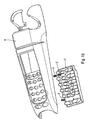
- FIG. 1a to 1d is represented by way of example a portable electronic payment terminal (wired or wireless).
- the terminal comprises a chassis 3 receiving constituent elements of the terminal, such as a printer, a memory card reader.
- the frame is removed and the terminal elements are mounted directly on the inner surfaces of a housing.
- the terminal further comprises a keyboard.
- a keyboard membrane 1 preferably of elastomeric material, can form the keys of the keyboard.
- the keyboard membrane 1 can be clipped on an electronic circuit 2 in particular to detect the depression of the keyboard keys.
- the electronic circuit 2 is preferably a multi-layer circuit.
- the surface of circuit 2 intended to be in contact with the keyboard membrane 1 comprises electrical contacts 21 forming conductive track ends extending in the inner layers of the circuit.
- the terminal further comprises a display screen 4, the screen can be mounted directly on the electronic circuit 2.
- the terminal comprises a housing that can be formed essentially of two parts, an upper cover 5 and a lower cover 6 (see FIG. figure 1d ).
- the top cover includes apertures allowing access to the keys of the keyboard and to see the display screen.
- Anti-intrusion devices according to the invention can be provided at the top cover 5.
- three anti-intrusion devices 52, 53, 54 are provided on the inner surface 51 of the top cover 5.
- each anti-intrusion device comprises a spring 3 arranged to act electrically on the electronic circuit 2 by means of the elastomeric membrane 2.
- An anti-intrusion device according to the invention may also be provided at the lower cover 6, the lower cover being the part of the housing on which the terminal in normal operation.
- an anti-intrusion device 62 is provided on the inner surface 61 of the lower cover. This device makes it possible to detect attempts to open the housing by the lower cover, which generally comprises a battery access door.
- the anti-intrusion device comprises at least one spring 3, arranged to be under pressure and to act electrically on the electronic circuit 2 when the housing is closed, and no longer act on the electronic circuit when the housing is open.
- An end of the spring 3 is preferably attached to an inner surface of the housing. In this way, the mounting of a terminal is simplified. In addition, the spring being secured to the housing, any opening of the housing directly drives the spring.
- the other end of the spring is intended to be in contact with the keyboard membrane 1, in which at least one button 11 is molded.
- membrane is arranged so that the spring presses the button when the housing is closed, and so that the spring leaves the button at rest when the housing is open.
- the button is arranged to act on the electronic circuit when it is pressurized by the spring, and no longer act on the electronic circuit when it is left at rest.
- the operation of the anti-intrusion device is as follows.
- the spring is under pressure. It exerts a pressure on the button 11, this pressure being sufficient to keep the button in a depressed state.
- the spring is at rest. No pressure being exerted on the button 11, the button is in a state of rest in which it does not act on the electronic circuit, as represented on the figure 2 .
- the spring moves away from the membrane, which gives him the opportunity to lie down.
- the spring first elongates while maintaining contact with the membrane button. As the spring lengthens, the pressure it exerts on the button 11 decreases gradually. At a given pressure threshold, the pressure exerted on the button is not sufficient to keep the button depressed. The button then goes into a state of rest in which it no longer acts on the electronic circuit. This transition can then be detected as an intrusion by the electronic circuit.
- This embodiment thus makes it possible to ensure a reliable transition from the depressed state to the idle state of the button during an intrusion, that is to say when the housing is opened.
- the use of the spring avoids false alarms, especially in case of simple shocks.
- the action of the button on the electronic circuit is made by an electrical contact between a conductive portion 12 of the button and conductive tracks of the circuit.
- the conductive portion 12 may be formed by a conductive surface such as a gold pellet or a carbon deposit.
- the button has a shoulder 13 arranged to hold the spring in position relative to the button. This shoulder not only keeps the spring centered in relation to the button, but also facilitate assembly.
- the membrane in which is molded an anti-intrusion device button is not necessarily a keyboard membrane.
- the spring 3 of the anti-intrusion device acts directly on an electronic circuit 31, and not via a membrane.
- the action of the spring on the electronic circuit is made by an electrical contact between a conductive part of the spring and conductive tracks of the circuit (see figure 5 ).
- the anti-intrusion device further comprises a guiding device 62 of the spring.
- the spring is placed in the guiding device.
- the guiding device 62 is arranged to guide the spring along the longitudinal axis of the spring. The guiding device makes the anti-intrusion device more reliable by guiding the stroke of the spring. It also keeps the spring in place.
- the guiding device can be molded directly into the internal surface of the casing as shown in FIGS. figures 2 or 3 .
- the guiding device may also be formed by a piece independent of the housing, this part being fixed to an inner surface of the housing. This allows for example to provide a modular anti-intrusion device, wherein a spring is already fixed in a guide device, the guide device being formed by an independent piece.
- the guiding device 62 has a substantially cylindrical recess, recess in which is intended to be placed the spring.
- the guiding device thus makes it possible to protect the spring of the anti-intrusion device.
- the guiding device makes it possible to protect the button 11 of the membrane by partially hiding it. This prevents a fraudster can access it directly.
- the guiding device comprises a wedge to limit the spring stroke. This allows to predict small springs, more sensitive to the opening movements of the case.
- the wedge may be formed by ribs 41, 42, 43, 44 of material provided inside the cylindrical recess.
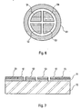
- FIG 5 is represented an example of electrical contacts of an electronic circuit on which acts a spring according to the invention in the embodiment described in connection with the figure 3 .
- the electrical contacts are at least two in number. They can be four in number 51, 52, 53, 54.
- the spring When the spring is in contact with the electronic circuit, its last turn 55 electrically connects the different contacts or at least two of them. Note that the same form of electrical contacts can be used in the embodiment described in connection with the figure 2 , the conductive part under the button replacing the role of the spring.
- a conductive area 61 may be added around the electrical contacts 51, 52, 53, 54 of the circuit.
- the conductive zone is connected to a determined potential, such as a mass of the electronic circuit.
- the conductive zone may be formed by a ring-shaped track surrounding the contacts 51, 52, 53, 54.
- the figure 7 presents a section of an exemplary embodiment of such a circuit.
- the circuit may comprise an insulating resin layer forming a support 72, carrying a copper layer etched by conventional techniques.
- the copper layer comprises for example a ground plane 71, including recesses at the locations of the contacts 51, 52, 53, 54, and almost completely covering the circuit.
- the ground plane 71 can be in turn covered with an insulating varnish 73 almost entirely.
- the contacts 51, 52, 53, 54 may be formed by gold deposits above the copper layer.
- the conductive zone 61 may be formed by a ring-shaped gold deposit, above the copper ground plane, in an area not covered with varnish.
Landscapes
- Engineering & Computer Science (AREA)
- General Physics & Mathematics (AREA)
- Physics & Mathematics (AREA)
- Computer Security & Cryptography (AREA)
- Theoretical Computer Science (AREA)
- Computer Hardware Design (AREA)
- Business, Economics & Management (AREA)
- Strategic Management (AREA)
- General Business, Economics & Management (AREA)
- Accounting & Taxation (AREA)
- Computer Networks & Wireless Communication (AREA)
- Microelectronics & Electronic Packaging (AREA)
- Software Systems (AREA)
- General Engineering & Computer Science (AREA)
- Push-Button Switches (AREA)
- Cash Registers Or Receiving Machines (AREA)
- Drying Of Solid Materials (AREA)
- Cleaning Or Drying Semiconductors (AREA)
- Control Of Vending Devices And Auxiliary Devices For Vending Devices (AREA)
- Details Of Connecting Devices For Male And Female Coupling (AREA)
Description
- La présente invention concerne un dispositif anti-intrusion pour la protection de boîtiers. Elle s'applique notamment à la protection d'un boîtier d'un terminal de paiement électronique ou d'un boîtier de saisie de code confidentiel (connu sous le nom de "PIN-Pad" dans la littérature anglo-saxonne).
- Un terminal de paiement électronique comporte un boîtier dans lequel sont prévus notamment un écran d'information, un lecteur de carte à mémoire, un clavier sur lequel un client peut saisir un code confidentiel, et des moyens de traitement associés au lecteur et au clavier pour effectuer les vérifications et la transaction. Les moyens de traitements comprennent des circuits électroniques permettant de réaliser des fonctions sensibles, telle que la vérification la validité du code saisi par le client.
- Certains terminaux peuvent être modifiés de façon frauduleuse pour altérer leur fonctionnement, et par exemple enregistrer les codes confidentiels saisis par les clients ou débiter un montant supérieur à celui affiché par l'écran d'information. Afin d'éviter ces fraudes, on prévoit des dispositifs de protection contre l'intrusion dans un boîtier. Ces dispositifs permettent de détecter toute ouverture du boîtier, les moyens de traitements étant désactivés en cas d'ouverture. Par exemple, la demande de brevet français n°
00 03465, déposée le 17/03/2000 FR 2 806 507 - La demande de brevet français déposée le 20/10/2000 et publiée sous le numéro
FR 2 815 733 - L'invention vise à apporter une solution technique alternative à ce problème, cette solution étant économique et facile à mettre en oeuvre. L'invention présente par ailleurs l'avantage d'être robuste et de présenter une fiabilité durable dans le temps grâce à l'utilisation d'un ressort. L'invention a aussi pour avantage qu'elle évite de détecter des ouvertures de manière intempestives, notamment lorsque le boîtier est soumis à des chocs ou à des vibrations. A cet effet, le dispositif anti-intrusion selon l'invention comprend au moins un ressort, le ressort étant agencé de manière à être sous pression et à agir électriquement sur un circuit électronique lorsque le boîtier est fermé, et à ne plus agir sur le circuit électronique lorsque le boîtier est ouvert.
- D'autres caractéristiques et avantages de l'invention apparaîtront à la lecture de la description détaillée suivante présentée à titre d'illustration non limitative et faite en référence aux figures annexées, lesquelles représentent :
- les
figures 1a à 1d , des éléments d'un terminal de paiement électronique dans des vues en perspective ; - la
figure 2 , le détail d'un dispositif anti-intrusion dans une vue en coupe ; - la
figure 3 , le détail d'un autre mode de réalisation de l'invention dans une vue en coupe ; - la
figure 4 , un exemple de dispositif de guidage selon un mode de réalisation avantageux de l'invention ; - la
figure 5 , un exemple de contacts électriques d'un circuit électronique sur lequel agit un ressort selon l'invention - les
figures 6 et 7 , un exemple de réalisation avantageux dans lequel le circuit sur lequel agit le dispositif anti-intrusion comporte au moins une zone conductrice à un potentiel déterminé, placée autour de l'endroit où agit le ressort sur le circuit. - On se réfère maintenant aux
figures 1a à 1d sur laquelle est représenté à titre d'exemple un terminal de paiement électronique de type portable (avec ou sans fil). - On se réfère à la
figure 1a . Le terminal comprend un châssis 3 recevant des éléments constitutifs du terminal, tel qu'une imprimante, un lecteur de carte à mémoire. Selon une variante de réalisation non représentée, le châssis est supprimé et les éléments du terminal sont montés directement sur les surfaces internes d'un boîtier. - Le terminal comprend en outre un clavier. Une membrane clavier 1, de préférence en matière élastomère, peut former les touches du clavier. La membrane clavier 1 peut être clipsée sur un circuit électronique 2 permettant notamment de détecter l'enfoncement des touches du clavier. Le circuit électronique 2 est de préférence un circuit multi-couche. La surface du circuit 2 destinée à être en contact avec la membrane clavier 1 comporte des contacts électriques 21, formant des extrémités de pistes conductrices se prolongeant dans des couches internes du circuit.
- Le terminal comprend en outre un écran de visualisation 4, l'écran pouvant être monté directement sur le circuit électronique 2.
- On se réfère aux
figures 1b et 1c . Le terminal comprend un boîtier pouvant être formé essentiellement de deux pièces, un capot supérieur 5 et un capot inférieur 6 (voir lafigure 1d ). Le capot supérieur comprend des ouvertures permettant un accès aux touches du clavier et de voir l'écran de visualisation. Des dispositifs anti-intrusion selon l'invention peuvent être prévus au niveau du capot supérieur 5. Dans l'exemple représenté, trois dispositifs anti-intrusion 52, 53, 54 sont prévus sur la surface interne 51 du capot supérieur 5. Selon un mode de réalisation avantageux, chaque dispositif anti-intrusion comprend un ressort 3 agencé pour agir électriquement sur le circuit électronique 2 par l'intermédiaire de la membrane élastomère 2. - On se réfère à la
figure 1d . Un dispositif anti-intrusion selon l'invention peut en outre être prévu au niveau du capot inférieur 6, le capot inférieur étant la partie du boîtier sur laquelle repose le terminal en fonctionnement normal. Dans l'exemple représenté, un dispositif anti-intrusion 62 est prévu sur la surface interne 61 du capot inférieur. Ce dispositif permet de détecter les tentatives d'ouverture du boîtier par le capot inférieur, lequel comprend généralement une trappe d'accès à une batterie. - On se réfère maintenant à la
figure 2 sur laquelle est représenté plus en détail un dispositif anti-intrusion prévu sur la surface intérieure 51 du capot supérieur. Le dispositif anti-intrusion comporte au moins un ressort 3, agencé de manière à être sous pression et à agir électriquement sur le circuit électronique 2 lorsque le boîtier est fermé, et à ne plus agir sur le circuit électronique lorsque le boîtier est ouvert. - Une extrémité du ressort 3 est de préférence fixée à une surface interne du boîtier. De cette manière, le montage d'un terminal est simplifié. De plus, le ressort étant solidaire du boîtier, toute ouverture du boîtier entraîne directement le ressort.
- L'autre extrémité du ressort est destinée à être en contact avec la membrane clavier 1, dans laquelle est moulée au moins un bouton 11. La membrane est agencée de sorte que le ressort presse sur le bouton lorsque le boîtier est fermé, et de sorte que le ressort laisse le bouton au repos lorsque le boîtier est ouvert. Le bouton est agencé de manière à agir sur le circuit électronique lorsqu'il est mis sous pression par le ressort, et à ne plus agir sur le circuit électronique lorsqu'il est laissé au repos.
- Le fonctionnement du dispositif anti-intrusion est le suivant. Lorsque le boîtier est fermé, le ressort est sous pression. Il exerce une pression sur le bouton 11, cette pression étant suffisante pour maintenir le bouton dans un état enfoncé. Lorsque le boîtier est ouvert, le ressort est au repos. Aucune pression n'étant exercée sur le bouton 11, le bouton se trouve dans un état de repos dans laquelle il n'agit pas sur le circuit électronique, tel que représenté sur la
figure 2 . - Lors du mouvement d'ouverture du boîtier, le ressort s'éloigne de la membrane, ce qui lui laisse la possibilité de s'allonger. Le ressort s'allonge d'abord tout en maintenant un contact avec le bouton de la membrane. A mesure que le ressort s'allonge, la pression qu'il exerce sur le bouton 11 diminue progressivement. A un seuil de pression donné, la pression exercée sur le bouton n'est pas suffisante pour maintenir le bouton enfoncé. Le bouton passe alors dans un état de repos dans lequel il n'agit plus sur le circuit électronique. Cette transition peut alors être détectée comme une intrusion par le circuit électronique.
- Ce mode de réalisation permet ainsi d'assurer une transition fiable de l'état enfoncé à l'état de repos du bouton lors d'une intrusion, c'est à dire lors d'une ouverture du boîtier. L'emploi du ressort évite des fausses alertes, notamment en cas de simples chocs.
- Selon un mode de réalisation pratique et simple à mettre en oeuvre, l'action du bouton sur le circuit électronique se fait par un contact électrique entre une partie conductrice 12 du bouton et des pistes conductrices du circuit. La partie conductrice 12 peut être formée par une surface conductrice telle qu'une pastille dorée ou un dépôt de carbone.
- Selon un mode de réalisation avantageux, le bouton présente un épaulement 13 agencé pour maintenir le ressort en position par rapport au bouton. Cet épaulement permet non seulement de maintenir le ressort en position centrée par rapport au bouton, mais aussi de faciliter le montage.
- Bien entendu, la membrane dans laquelle est moulé un bouton de dispositif anti-intrusion n'est pas nécessairement une membrane clavier.
- On se réfère maintenant à la
figure 3 sur laquelle est représenté plus en détail le dispositif anti-intrusion prévu sur la surface interne 61 du capot inférieur. Dans ce mode de réalisation de l'invention, le ressort 3 du dispositif anti-intrusion agit directement sur un circuit électronique 31, et non par l'intermédiaire d'une membrane. L'action du ressort sur le circuit électronique se fait par un contact électrique entre une partie conductrice du ressort et des pistes conductrices du circuit (voir lafigure 5 ). - Selon un mode de réalisation avantageux de l'invention, le dispositif anti-intrusion comprend en outre un dispositif de guidage 62 du ressort. Le ressort est placé dans le dispositif de guidage. Le dispositif de guidage 62 est agencé pour guider le ressort selon l'axe longitudinal du ressort. Le dispositif de guidage permet de rendre le dispositif anti-intrusion plus fiable, en guidant la course du ressort. Il permet en outre de maintenir le ressort en place.
- Selon un mode de réalisation pratique, le dispositif de guidage peut être moulé directement dans la surface interne du boîtier tel que représenté sur les
figures 2 ou3 . Bien entendu; le dispositif de guidage peut aussi être formé par une pièce indépendante du boîtier, cette pièce étant fixée à une surface interne du boîtier. Ceci permet par exemple de prévoir un dispositif anti-intrusion modulaire, dans lequel un ressort est déjà fixé dans un dispositif de guidage, le dispositif de guidage étant formé par une pièce indépendante. - On se réfère à la
figure 4 . Selon un mode de réalisation avantageux, le dispositif de guidage 62 présente un évidement sensiblement cylindrique, évidement dans lequel est destiné à être placé le ressort. Le dispositif de guidage permet ainsi de protéger le ressort du dispositif anti-intrusion. De plus, dans le mode de réalisation avantageux décrit en relation avec lafigure 2 , le dispositif de guidage permet de protéger le bouton 11 de la membrane en le cachant partiellement. Ceci évite qu'un fraudeur puisse y accéder directement. - Selon un mode de réalisation avantageux, le dispositif de guidage comprend une cale pour limiter la course du ressort. Ceci permet de prévoir des ressorts de petites tailles, plus sensibles aux mouvements d'ouvertures du boîtier. La cale peut être formée par des nervures 41, 42, 43, 44 de matière prévues à l'intérieur de l'évidement cylindrique.
- On se réfère à la
figure 5 sur laquelle est représenté un exemple de contacts électriques d'un circuit électronique sur lequel agit un ressort selon l'invention dans le mode de réalisation décrit en relation avec lafigure 3 . Les contacts électriques sont au moins au nombre de deux. Ils peuvent être au nombre de quatre 51, 52, 53, 54. Lorsque le ressort est en contact avec le circuit électronique, sa dernière spire 55 relie électriquement les différents contacts ou au moins deux d'entre eux. On notera que la même forme de contacts électriques peut être utilisée dans le mode de réalisation décrit en relation avec lafigure 2 , la partie conductrice sous le bouton remplaçant le rôle du ressort. - On se réfère aux
figures 6 et 7 sur lesquelles est représenté un exemple de réalisation avantageux. Une zone conductrice 61 peut être ajoutée autour des contacts électriques 51, 52, 53, 54 du circuit. La zone conductrice est reliée à un potentiel déterminé, tel que une masse du circuit électronique. La zone conductrice peut être formée par une piste en forme d'anneau entourant les contacts 51, 52, 53, 54. Ainsi, si quelqu'un tente d'injecter un produit conducteur au niveau des contacts électriques 51, 52, 53, 54 (à l'aide d'une seringue par exemple), un contact électrique sera établi non seulement entre les contacts 51, 52, 53, 54, mais aussi avec la zone conductrice 61. Les contacts 51 , 52, 53, 54 seront alors mis au potentiel déterminé, ce qui pourra être détecté comme une tentative d'intrusion. - La
figure 7 présente u ne section d'un exemple de réalisation d'un tel circuit. Le circuit peut comprendre une couche de résine isolante formant un support 72, portant une couche de cuivre gravée par des techniques conventionnelles. La couche de cuivre comprend par exemple un plan de masse 71, comprenant des évidements au niveau des emplacements des contacts 51, 52, 53, 54, et recouvrant presque en totalité le circuit. Le plan de masse 71 peut être quant à lui recouvert d'un vernis isolant 73 presque en totalité. Les contacts 51, 52, 53, 54 peuvent être formés par des dépôts d'or au-dessus de la couche de cuivre. La zone conductrice 61 peut être formée par un dépôt d'or en forme d'anneau, au dessus du plan de masse en cuivre, dans une zone non recouverte de vernis.
Claims (7)
- Dispositif anti-intrusion pour détecter d'éventuelles tentatives d'ouverture d'un boîtier, comprenant au moins un ressort (3), le ressort étant agencé de manière à être sous pression et à agir électriquement sur un circuit électronique (31) lorsque le boîtier est fermé, et à ne plus agir sur le circuit électronique lorsque le boîtier est ouverte, caractérisé en ce que l'action du ressort sur le circuit électronique se fait directement par un contact électrique entre le ressort et des pistes conductrices (51, 52, 53, 54) du circuit.
- Dispositif selon la revendication 1 dans lequel une extrémité du ressort est fixée à une surface interne (61) du boîtier.
- Dispositif selon la revendication 1 dans lequel le ressort est placé dans un dispositif de guidage (62) agencé pour guider le ressort selon l'axe longitudinal dudit ressort.
- Dispositif selon la revendication précédente dans lequel le dispositif de guidage présente un évidement sensiblement cylindrique, évidement dans lequel est destiné à être placé le ressort.
- Dispositif selon la revendication 1 dans lequel le boîtier est un boîtier de terminal de paiement électronique ou de boîtier de saisie de code confidentiel.
- Dispositif selon la revendication 1 caractérisé en ce que lorsque le ressort est en contact avec le circuit électronique, la dernière spire (55) dudit ressort est reliée électriquement aux différents pistes conductrices (51, 52, 53, 54) ou au moins deux d'entre elles.
- Dispositif selon la revendication 6caractérisé en ce qu'une zone conductrice (61) est disposée autour des pistes conductrices (51, 52, 53, 54), la zone conductrice (61) étant reliée à un potentiel déterminé.
Applications Claiming Priority (2)
| Application Number | Priority Date | Filing Date | Title |
|---|---|---|---|
| FR0311726A FR2860643B1 (fr) | 2003-10-07 | 2003-10-07 | Dispositif anti-intrusion notamment pour terminal de paiement electronique |
| PCT/EP2004/052352 WO2005034157A1 (fr) | 2003-10-07 | 2004-09-29 | Dispositif anti-intrusion notamment pour terminal de paiement electronique |
Publications (2)
| Publication Number | Publication Date |
|---|---|
| EP1671341A1 EP1671341A1 (fr) | 2006-06-21 |
| EP1671341B1 true EP1671341B1 (fr) | 2011-03-23 |
Family
ID=34307490
Family Applications (1)
| Application Number | Title | Priority Date | Filing Date |
|---|---|---|---|
| EP04766864A Expired - Lifetime EP1671341B1 (fr) | 2003-10-07 | 2004-09-29 | Dispositif anti-intrusion notamment pour terminal de paiement electronique |
Country Status (8)
| Country | Link |
|---|---|
| US (1) | US7790993B2 (fr) |
| EP (1) | EP1671341B1 (fr) |
| CN (1) | CN1898760A (fr) |
| AT (1) | ATE503261T1 (fr) |
| AU (1) | AU2004278849A1 (fr) |
| DE (1) | DE602004031965D1 (fr) |
| FR (1) | FR2860643B1 (fr) |
| WO (1) | WO2005034157A1 (fr) |
Families Citing this family (12)
| Publication number | Priority date | Publication date | Assignee | Title |
|---|---|---|---|---|
| CA2509925C (fr) * | 2005-06-14 | 2014-09-30 | Ingenico Canada Ltd | Actionneur d'interrupteur antisabotage |
| FR2897702B1 (fr) * | 2006-02-22 | 2008-04-25 | Sagem Monetel Soc Par Actions | Dispositif anti-intrusion |
| FR2901896B1 (fr) * | 2006-06-02 | 2008-10-31 | Sagem Monetel Soc Par Actions | Dispositif de protection contre les intrusions d'appareil electronique |
| FR2910991B1 (fr) * | 2007-01-02 | 2009-07-31 | Ingenico Sa | Module de securite materiel,procede de mise en service et terminal de paiement electronique utilisant ce module |
| DE102007040637B8 (de) * | 2007-08-28 | 2009-08-13 | Hypercom Gmbh | Sicherheitstastatur |
| DE102008003264B4 (de) | 2008-01-04 | 2016-07-28 | Demmel Ag | Manipulationsgeschütze Tastatur mit Schutz gegen Ausbau der Tastenkappen |
| FR2934110B1 (fr) | 2008-07-16 | 2010-10-22 | Ingenico Sa | Dispositif de protection d'un composant electronique. |
| GB2468720B (en) * | 2009-03-20 | 2011-09-07 | Keymat Technology Ltd | A Component carrying a mechanism for detecting separation of the component from a part |
| FR3008527B1 (fr) * | 2013-07-12 | 2018-01-05 | Compagnie Ind Et Financiere D'ingenierie Ingenico | Terminal de paiement electronique comprenant un boitier ameliore. |
| PL2993609T3 (pl) * | 2014-09-02 | 2017-12-29 | Assa Ab | Odporna na ingerowanie elektroniczna jednostka sterująca |
| US10013582B2 (en) | 2014-12-29 | 2018-07-03 | Verifone, Inc. | Secure data entry device |
| FR3037688B1 (fr) | 2015-06-19 | 2017-07-14 | Ingenico Group | Systeme de securisation d'un dispositif de saisie |
Family Cites Families (5)
| Publication number | Priority date | Publication date | Assignee | Title |
|---|---|---|---|---|
| ATE107061T1 (de) * | 1989-08-03 | 1994-06-15 | Scheidt & Bachmann Gmbh | Vorrichtung zur eingabe von daten. |
| FR2806507B1 (fr) * | 2000-03-17 | 2003-09-05 | Dassault Automatismes | Membrane elastomere anti-intrusion pour boitiers electroniques securises |
| FR2815733B1 (fr) * | 2000-10-20 | 2003-03-21 | Ascom Monetel Sa | Clavier securise |
| US7259341B2 (en) * | 2005-09-22 | 2007-08-21 | Ingenico Canada Ltd. | Tamper switch actuator arrangement |
| JP4819518B2 (ja) * | 2006-02-09 | 2011-11-24 | キヤノン株式会社 | 電子機器 |
-
2003
- 2003-10-07 FR FR0311726A patent/FR2860643B1/fr not_active Expired - Fee Related
-
2004
- 2004-09-29 WO PCT/EP2004/052352 patent/WO2005034157A1/fr not_active Ceased
- 2004-09-29 AT AT04766864T patent/ATE503261T1/de not_active IP Right Cessation
- 2004-09-29 US US10/574,707 patent/US7790993B2/en active Active
- 2004-09-29 AU AU2004278849A patent/AU2004278849A1/en not_active Abandoned
- 2004-09-29 DE DE602004031965T patent/DE602004031965D1/de not_active Expired - Lifetime
- 2004-09-29 CN CNA2004800362971A patent/CN1898760A/zh active Pending
- 2004-09-29 EP EP04766864A patent/EP1671341B1/fr not_active Expired - Lifetime
Also Published As
| Publication number | Publication date |
|---|---|
| DE602004031965D1 (de) | 2011-05-05 |
| CN1898760A (zh) | 2007-01-17 |
| FR2860643B1 (fr) | 2006-02-17 |
| ATE503261T1 (de) | 2011-04-15 |
| FR2860643A1 (fr) | 2005-04-08 |
| US7790993B2 (en) | 2010-09-07 |
| EP1671341A1 (fr) | 2006-06-21 |
| WO2005034157A1 (fr) | 2005-04-14 |
| US20080230355A1 (en) | 2008-09-25 |
| AU2004278849A1 (en) | 2005-04-14 |
Similar Documents
| Publication | Publication Date | Title |
|---|---|---|
| EP1671341B1 (fr) | Dispositif anti-intrusion notamment pour terminal de paiement electronique | |
| EP1269440B1 (fr) | Membrane elastomere anti-intrusion pour boitiers electroniques securises | |
| EP2030143B1 (fr) | Dispositif de protection contre les intrusions d'appareils electroniques | |
| EP2146562B1 (fr) | Dispositif de protection d'un composant électronique | |
| EP2194489A1 (fr) | Carte électronique ayant des moyens de commande | |
| EP1346384B1 (fr) | Clavier securise | |
| EP3229166B1 (fr) | Détection d'ouverture d'un dispositif de saisie de données | |
| EP3379389B1 (fr) | Clavier sécurisé pour dispositif électronique de saisie de données | |
| EP1826702B1 (fr) | Dispositif anti-intrusion | |
| EP2102832A1 (fr) | Boitier securise | |
| EP3295365B1 (fr) | Détection d'ouverture d'un dispositif de saisie de données | |
| EP4241192A1 (fr) | Module de securite, terminal de paiement electronique, procede de detection correspondant | |
| FR3158173A3 (fr) | Dispositif de saisie de données à clavier perfectionné formant notamment terminal de paiement. | |
| FR2908552A1 (fr) | Interrupteur de circuit electronique protege contre un acces exterieur | |
| KR20160029189A (ko) | 암호화 핀패드 | |
| FR2985338A1 (fr) | Clavier securise |
Legal Events
| Date | Code | Title | Description |
|---|---|---|---|
| PUAI | Public reference made under article 153(3) epc to a published international application that has entered the european phase |
Free format text: ORIGINAL CODE: 0009012 |
|
| 17P | Request for examination filed |
Effective date: 20060404 |
|
| AK | Designated contracting states |
Kind code of ref document: A1 Designated state(s): AT BE BG CH CY CZ DE DK EE ES FI FR GB GR HU IE IT LI LU MC NL PL PT RO SE SI SK TR |
|
| DAX | Request for extension of the european patent (deleted) | ||
| 17Q | First examination report despatched |
Effective date: 20080416 |
|
| GRAP | Despatch of communication of intention to grant a patent |
Free format text: ORIGINAL CODE: EPIDOSNIGR1 |
|
| GRAS | Grant fee paid |
Free format text: ORIGINAL CODE: EPIDOSNIGR3 |
|
| GRAA | (expected) grant |
Free format text: ORIGINAL CODE: 0009210 |
|
| AK | Designated contracting states |
Kind code of ref document: B1 Designated state(s): AT BE BG CH CY CZ DE DK EE ES FI FR GB GR HU IE IT LI LU MC NL PL PT RO SE SI SK TR |
|
| REG | Reference to a national code |
Ref country code: GB Ref legal event code: FG4D Free format text: NOT ENGLISH |
|
| REG | Reference to a national code |
Ref country code: CH Ref legal event code: EP |
|
| REG | Reference to a national code |
Ref country code: IE Ref legal event code: FG4D |
|
| REF | Corresponds to: |
Ref document number: 602004031965 Country of ref document: DE Date of ref document: 20110505 Kind code of ref document: P |
|
| REG | Reference to a national code |
Ref country code: DE Ref legal event code: R096 Ref document number: 602004031965 Country of ref document: DE Effective date: 20110505 |
|
| REG | Reference to a national code |
Ref country code: NL Ref legal event code: VDEP Effective date: 20110323 |
|
| PG25 | Lapsed in a contracting state [announced via postgrant information from national office to epo] |
Ref country code: GR Free format text: LAPSE BECAUSE OF FAILURE TO SUBMIT A TRANSLATION OF THE DESCRIPTION OR TO PAY THE FEE WITHIN THE PRESCRIBED TIME-LIMIT Effective date: 20110624 Ref country code: SE Free format text: LAPSE BECAUSE OF FAILURE TO SUBMIT A TRANSLATION OF THE DESCRIPTION OR TO PAY THE FEE WITHIN THE PRESCRIBED TIME-LIMIT Effective date: 20110323 |
|
| PG25 | Lapsed in a contracting state [announced via postgrant information from national office to epo] |
Ref country code: CY Free format text: LAPSE BECAUSE OF FAILURE TO SUBMIT A TRANSLATION OF THE DESCRIPTION OR TO PAY THE FEE WITHIN THE PRESCRIBED TIME-LIMIT Effective date: 20110323 Ref country code: AT Free format text: LAPSE BECAUSE OF FAILURE TO SUBMIT A TRANSLATION OF THE DESCRIPTION OR TO PAY THE FEE WITHIN THE PRESCRIBED TIME-LIMIT Effective date: 20110323 Ref country code: SI Free format text: LAPSE BECAUSE OF FAILURE TO SUBMIT A TRANSLATION OF THE DESCRIPTION OR TO PAY THE FEE WITHIN THE PRESCRIBED TIME-LIMIT Effective date: 20110323 Ref country code: FI Free format text: LAPSE BECAUSE OF FAILURE TO SUBMIT A TRANSLATION OF THE DESCRIPTION OR TO PAY THE FEE WITHIN THE PRESCRIBED TIME-LIMIT Effective date: 20110323 Ref country code: BG Free format text: LAPSE BECAUSE OF FAILURE TO SUBMIT A TRANSLATION OF THE DESCRIPTION OR TO PAY THE FEE WITHIN THE PRESCRIBED TIME-LIMIT Effective date: 20110623 |
|
| REG | Reference to a national code |
Ref country code: IE Ref legal event code: FD4D |
|
| PG25 | Lapsed in a contracting state [announced via postgrant information from national office to epo] |
Ref country code: EE Free format text: LAPSE BECAUSE OF FAILURE TO SUBMIT A TRANSLATION OF THE DESCRIPTION OR TO PAY THE FEE WITHIN THE PRESCRIBED TIME-LIMIT Effective date: 20110323 Ref country code: PT Free format text: LAPSE BECAUSE OF FAILURE TO SUBMIT A TRANSLATION OF THE DESCRIPTION OR TO PAY THE FEE WITHIN THE PRESCRIBED TIME-LIMIT Effective date: 20110725 |
|
| PG25 | Lapsed in a contracting state [announced via postgrant information from national office to epo] |
Ref country code: RO Free format text: LAPSE BECAUSE OF FAILURE TO SUBMIT A TRANSLATION OF THE DESCRIPTION OR TO PAY THE FEE WITHIN THE PRESCRIBED TIME-LIMIT Effective date: 20110323 Ref country code: SK Free format text: LAPSE BECAUSE OF FAILURE TO SUBMIT A TRANSLATION OF THE DESCRIPTION OR TO PAY THE FEE WITHIN THE PRESCRIBED TIME-LIMIT Effective date: 20110323 Ref country code: CZ Free format text: LAPSE BECAUSE OF FAILURE TO SUBMIT A TRANSLATION OF THE DESCRIPTION OR TO PAY THE FEE WITHIN THE PRESCRIBED TIME-LIMIT Effective date: 20110323 Ref country code: ES Free format text: LAPSE BECAUSE OF FAILURE TO SUBMIT A TRANSLATION OF THE DESCRIPTION OR TO PAY THE FEE WITHIN THE PRESCRIBED TIME-LIMIT Effective date: 20110704 |
|
| PG25 | Lapsed in a contracting state [announced via postgrant information from national office to epo] |
Ref country code: NL Free format text: LAPSE BECAUSE OF FAILURE TO SUBMIT A TRANSLATION OF THE DESCRIPTION OR TO PAY THE FEE WITHIN THE PRESCRIBED TIME-LIMIT Effective date: 20110323 |
|
| PLBE | No opposition filed within time limit |
Free format text: ORIGINAL CODE: 0009261 |
|
| STAA | Information on the status of an ep patent application or granted ep patent |
Free format text: STATUS: NO OPPOSITION FILED WITHIN TIME LIMIT |
|
| PG25 | Lapsed in a contracting state [announced via postgrant information from national office to epo] |
Ref country code: IE Free format text: LAPSE BECAUSE OF FAILURE TO SUBMIT A TRANSLATION OF THE DESCRIPTION OR TO PAY THE FEE WITHIN THE PRESCRIBED TIME-LIMIT Effective date: 20110323 |
|
| 26N | No opposition filed |
Effective date: 20111227 |
|
| PG25 | Lapsed in a contracting state [announced via postgrant information from national office to epo] |
Ref country code: PL Free format text: LAPSE BECAUSE OF FAILURE TO SUBMIT A TRANSLATION OF THE DESCRIPTION OR TO PAY THE FEE WITHIN THE PRESCRIBED TIME-LIMIT Effective date: 20110323 Ref country code: DK Free format text: LAPSE BECAUSE OF FAILURE TO SUBMIT A TRANSLATION OF THE DESCRIPTION OR TO PAY THE FEE WITHIN THE PRESCRIBED TIME-LIMIT Effective date: 20110323 |
|
| BERE | Be: lapsed |
Owner name: THALES Effective date: 20110930 |
|
| REG | Reference to a national code |
Ref country code: DE Ref legal event code: R097 Ref document number: 602004031965 Country of ref document: DE Effective date: 20111227 |
|
| PG25 | Lapsed in a contracting state [announced via postgrant information from national office to epo] |
Ref country code: MC Free format text: LAPSE BECAUSE OF NON-PAYMENT OF DUE FEES Effective date: 20110930 |
|
| REG | Reference to a national code |
Ref country code: CH Ref legal event code: PL |
|
| PG25 | Lapsed in a contracting state [announced via postgrant information from national office to epo] |
Ref country code: IT Free format text: LAPSE BECAUSE OF FAILURE TO SUBMIT A TRANSLATION OF THE DESCRIPTION OR TO PAY THE FEE WITHIN THE PRESCRIBED TIME-LIMIT Effective date: 20110323 |
|
| PG25 | Lapsed in a contracting state [announced via postgrant information from national office to epo] |
Ref country code: BE Free format text: LAPSE BECAUSE OF NON-PAYMENT OF DUE FEES Effective date: 20110930 |
|
| PG25 | Lapsed in a contracting state [announced via postgrant information from national office to epo] |
Ref country code: LI Free format text: LAPSE BECAUSE OF NON-PAYMENT OF DUE FEES Effective date: 20110930 Ref country code: CH Free format text: LAPSE BECAUSE OF NON-PAYMENT OF DUE FEES Effective date: 20110930 |
|
| PG25 | Lapsed in a contracting state [announced via postgrant information from national office to epo] |
Ref country code: LU Free format text: LAPSE BECAUSE OF NON-PAYMENT OF DUE FEES Effective date: 20110929 |
|
| PG25 | Lapsed in a contracting state [announced via postgrant information from national office to epo] |
Ref country code: TR Free format text: LAPSE BECAUSE OF FAILURE TO SUBMIT A TRANSLATION OF THE DESCRIPTION OR TO PAY THE FEE WITHIN THE PRESCRIBED TIME-LIMIT Effective date: 20110323 |
|
| PG25 | Lapsed in a contracting state [announced via postgrant information from national office to epo] |
Ref country code: HU Free format text: LAPSE BECAUSE OF FAILURE TO SUBMIT A TRANSLATION OF THE DESCRIPTION OR TO PAY THE FEE WITHIN THE PRESCRIBED TIME-LIMIT Effective date: 20110323 |
|
| REG | Reference to a national code |
Ref country code: FR Ref legal event code: PLFP Year of fee payment: 13 |
|
| REG | Reference to a national code |
Ref country code: FR Ref legal event code: PLFP Year of fee payment: 14 |
|
| REG | Reference to a national code |
Ref country code: FR Ref legal event code: CA Effective date: 20180727 Ref country code: FR Ref legal event code: CD Owner name: VERIFFONE SYSTEMS FRANCE SAS, FR Effective date: 20180727 Ref country code: FR Ref legal event code: TP Owner name: VERIFFONE SYSTEMS FRANCE SAS, FR Effective date: 20180727 |
|
| REG | Reference to a national code |
Ref country code: FR Ref legal event code: CA Effective date: 20180727 Ref country code: FR Ref legal event code: CD Owner name: VERIFFONE SYSTEMS FRANCE SAS, FR Effective date: 20180727 Ref country code: FR Ref legal event code: CJ Effective date: 20180727 |
|
| REG | Reference to a national code |
Ref country code: FR Ref legal event code: PLFP Year of fee payment: 15 |
|
| PGFP | Annual fee paid to national office [announced via postgrant information from national office to epo] |
Ref country code: GB Payment date: 20220927 Year of fee payment: 19 Ref country code: DE Payment date: 20220928 Year of fee payment: 19 |
|
| PGFP | Annual fee paid to national office [announced via postgrant information from national office to epo] |
Ref country code: FR Payment date: 20220926 Year of fee payment: 19 |
|
| P01 | Opt-out of the competence of the unified patent court (upc) registered |
Effective date: 20230529 |
|
| REG | Reference to a national code |
Ref country code: DE Ref legal event code: R119 Ref document number: 602004031965 Country of ref document: DE |
|
| GBPC | Gb: european patent ceased through non-payment of renewal fee |
Effective date: 20230929 |
|
| PG25 | Lapsed in a contracting state [announced via postgrant information from national office to epo] |
Ref country code: GB Free format text: LAPSE BECAUSE OF NON-PAYMENT OF DUE FEES Effective date: 20230929 |
|
| PG25 | Lapsed in a contracting state [announced via postgrant information from national office to epo] |
Ref country code: GB Free format text: LAPSE BECAUSE OF NON-PAYMENT OF DUE FEES Effective date: 20230929 Ref country code: FR Free format text: LAPSE BECAUSE OF NON-PAYMENT OF DUE FEES Effective date: 20230930 Ref country code: DE Free format text: LAPSE BECAUSE OF NON-PAYMENT OF DUE FEES Effective date: 20240403 |