EP1671800A2 - Système de tête d'impression minimisant l'erreur de pas - Google Patents
Système de tête d'impression minimisant l'erreur de pas Download PDFInfo
- Publication number
- EP1671800A2 EP1671800A2 EP05027393A EP05027393A EP1671800A2 EP 1671800 A2 EP1671800 A2 EP 1671800A2 EP 05027393 A EP05027393 A EP 05027393A EP 05027393 A EP05027393 A EP 05027393A EP 1671800 A2 EP1671800 A2 EP 1671800A2
- Authority
- EP
- European Patent Office
- Prior art keywords
- ink
- orifice
- jetting
- assembly
- ink orifice
- Prior art date
- Legal status (The legal status is an assumption and is not a legal conclusion. Google has not performed a legal analysis and makes no representation as to the accuracy of the status listed.)
- Withdrawn
Links
- 239000000758 substrate Substances 0.000 claims abstract description 49
- 230000000712 assembly Effects 0.000 claims abstract description 36
- 238000000429 assembly Methods 0.000 claims abstract description 36
- 238000007641 inkjet printing Methods 0.000 claims abstract description 23
- 238000007639 printing Methods 0.000 claims abstract description 13
- 238000000034 method Methods 0.000 claims abstract description 10
- 238000010304 firing Methods 0.000 claims description 20
- 238000000151 deposition Methods 0.000 claims description 10
- 238000004519 manufacturing process Methods 0.000 description 6
- 230000008901 benefit Effects 0.000 description 3
- 230000008021 deposition Effects 0.000 description 3
- 238000010276 construction Methods 0.000 description 2
- 239000000463 material Substances 0.000 description 2
- 230000002745 absorbent Effects 0.000 description 1
- 239000002250 absorbent Substances 0.000 description 1
- 230000002411 adverse Effects 0.000 description 1
- 238000012423 maintenance Methods 0.000 description 1
- 238000012544 monitoring process Methods 0.000 description 1
- 230000035945 sensitivity Effects 0.000 description 1
- 230000004304 visual acuity Effects 0.000 description 1
Images
Classifications
-
- B—PERFORMING OPERATIONS; TRANSPORTING
- B41—PRINTING; LINING MACHINES; TYPEWRITERS; STAMPS
- B41J—TYPEWRITERS; SELECTIVE PRINTING MECHANISMS, i.e. MECHANISMS PRINTING OTHERWISE THAN FROM A FORME; CORRECTION OF TYPOGRAPHICAL ERRORS
- B41J2/00—Typewriters or selective printing mechanisms characterised by the printing or marking process for which they are designed
- B41J2/005—Typewriters or selective printing mechanisms characterised by the printing or marking process for which they are designed characterised by bringing liquid or particles selectively into contact with a printing material
- B41J2/01—Ink jet
- B41J2/21—Ink jet for multi-colour printing
- B41J2/2121—Ink jet for multi-colour printing characterised by dot size, e.g. combinations of printed dots of different diameter
- B41J2/2128—Ink jet for multi-colour printing characterised by dot size, e.g. combinations of printed dots of different diameter by means of energy modulation
-
- B—PERFORMING OPERATIONS; TRANSPORTING
- B41—PRINTING; LINING MACHINES; TYPEWRITERS; STAMPS
- B41J—TYPEWRITERS; SELECTIVE PRINTING MECHANISMS, i.e. MECHANISMS PRINTING OTHERWISE THAN FROM A FORME; CORRECTION OF TYPOGRAPHICAL ERRORS
- B41J2/00—Typewriters or selective printing mechanisms characterised by the printing or marking process for which they are designed
- B41J2/485—Typewriters or selective printing mechanisms characterised by the printing or marking process for which they are designed characterised by the process of building-up characters or image elements applicable to two or more kinds of printing or marking processes
- B41J2/505—Typewriters or selective printing mechanisms characterised by the printing or marking process for which they are designed characterised by the process of building-up characters or image elements applicable to two or more kinds of printing or marking processes from an assembly of identical printing elements
- B41J2/515—Typewriters or selective printing mechanisms characterised by the printing or marking process for which they are designed characterised by the process of building-up characters or image elements applicable to two or more kinds of printing or marking processes from an assembly of identical printing elements line printer type
Definitions
- the present invention relates to ink jet printing and, more particularly, relates to a print head system capable of minimizing stitch error during printing.
- ink jet printing is extremely popular in a wide variety of industries.
- ink jet printing is accomplished through the use of a print head.
- the print head includes a plurality of orifices each capable of depositing an ink drop upon a substrate to form a predetermined pattern, such as an image, text, and the like.
- the plurality of orifices contained in the print head are arranged in rows and columns and are each capable of depositing an ink drop to a defined pixel position grid (also defined as rows and columns) upon a substrate.
- This row and column arrangement of the orifices typically does not span the full number of rows or the full number of columns in the pixel position grid. Consequently, the print head and the substrate must be moved relative to each other to create the desired output to be printed.
- ink jet printing may be used in printing upon elongated substrates, such as paper rolls or sheets.
- the substrate is typically stopped at predetermined steps according to separate encoding systems that accurately track the longitudinal movement of the substrate.
- a line of ink is deposited along a row of pixels, which is often referred to as a print line.
- a first section of the image is printed across the substrate to define the entire row and a length of the columns.
- the substrate is then advanced a step and another entire row and an additional length of the columns is deposited. This process continues until the image is completed.
- the density of the ink deposits in the pixel grid is increased to provide improved resolving power. To an extent, this can be achieved by manufacturing the print head with a single lateral line of more closely spaced orifices. However, it should be understood that there are limits to the minimum spacing between adjacent orifices that can be achieved with today's manufacturing systems.
- Print heads can be made as wide as the area to be printed to promote single pass printing.
- the substrate is moved longitudinally as the print head is held stationary. An entire row of ink is deposited at a time to provide the single pass capability.
- stitch error results from a tolerance buildup-namely, the orifice relative positions, the print head position relative to adjacent overlapping print heads, any misalignment of the substrate, and other factors. Although tolerances could be tightened, such would increase the manufacturing, assembly, and maintenance costs of these systems. Therefore, it is desirable to overcome or at least minimize stitch error without requiring tighter tolerances.
- an ink jet printing assembly for printing on a substrate having an advantageous construction and method of use.
- the substrate is driven in a driving direction.
- the ink jet printing assembly includes a first jetting assembly having a first ink orifice and a second ink orifice and a second jetting assembly separate from the first jetting assembly having a third ink orifice.
- the third ink orifice is positioned between the first ink orifice and the second ink orifice in a cross substrate direction.
- a third jetting assembly, separate from the first and second jetting assemblies, includes a fourth ink orifice.
- the fourth ink orifice is aligned with the first ink orifice in the cross substrate direction.
- the first ink orifice is fired to produce at least one ink drop at a single pixel position and the fourth ink orifice is fired to produce multiple ink drops at the single pixel position to minimize a stitch error.
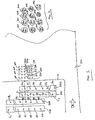
- FIG. 1 is a plan view illustrating the positional relationship of the plurality of jetting assemblies of the present invention.
- FIG. 2 is an enlarged plan view illustrating the ink drop deposition pattern upon the substrate according to the method of the present invention.
- an ink jet printing assembly having improved resolving capability, interchangeability, and reduced stitch error, in addition to many other benefits.
- a plurality of jetting assemblies or print heads 22 are illustrated, generally labeled from A-D.
- the plurality of jetting assemblies 22A-D are arranged in a manner to provide efficient, reliable, and simple high-resolution image production.
- Each of the plurality of jetting assemblies 22A-D is preferably identical in construction and ink depositing operation. Accordingly, they may be discussed collectively as jetting assembly 22.
- Jetting assembly 22 is operably coupled to an ink jet printing system (not shown), such as that described generally in commonly-assigned U.S. Provisional Patent Application No. 60/568,445, which is incorporated herein by reference.
- the ink jet printing system generally includes an umbilical that is operably coupled to an ink supply, a control device, or any other off-board system.
- the umbilical is further coupled to a mounting structure 16 that is adapted to carry the weight of the various components of the ink jet printing system.
- An ink tube is coupled between an onboard ink reservoir and the plurality of jetting assemblies 22.
- a substrate 100 in this case a roll of material, is driven through a drive path Z (see FIG. 1) as it travels through the ink jet printing system in a conventional manner.
- Each of the plurality of jetting assemblies 22 are fixedly, yet removably, coupled to mounting structure 16.
- each of the plurality of jetting assemblies 22 includes a plurality of ink orifices, generally labeled as A1, A2, A3, etc. for jetting assembly 22A and similarly for the remaining jetting assemblies 22B-D.
- A1, A2, A3, etc. for jetting assembly 22A and similarly for the remaining jetting assemblies 22B-D.
- the present invention may be used with any number of jetting assemblies having any number of ink orifices.
- four jetting assemblies 22A-D having ink orifices x1-x5 will be described where x represents either A-D.
- the present invention is not limited to jetting assemblies having the illustrated number of overlapping orifices. Other number of overlapping orifices may be used.
- Jetting assemblies 22A-D are arranged in an parallel relationship relative to each other and generally orthogonal to travel direction of substrate 100, generally indicated by the arrow Z of FIG. 1.
- Jetting assemblies 22A-D include orifices A1-An, B1-Bn, C1-Cn, and D1-Dn, respectively.
- Such orifices are operable to fire a series of ink drops. Specifically, such orifices are operable to discretely fire up to about seven ink drops repeatedly within quick succession.
- ink is pumped through a filter (not shown) and enters the ink reservoir through an ink tube.
- the ink travels down the ink tubes to each of the plurality of jetting assemblies 22.
- data from a controller is sent an integrated circuit board and a control signal is output to an onboard controller or chip on each of the plurality of jetting assemblies 22.
- This control signal commands a firing of a specific ink orifice, which produces between one and seven ink drops upon substrate 100.
- An encoder is used to provide a timing signal to the integrated circuit board.
- the encoder is capable of monitoring the drive movement of substrate 100 to provide the necessary position data for accurately firing the selected ink orifices.
- a high voltage (approx. 100V) is sent to the integrate circuit board, which is transmitted in the form of a control signal to each of the plurality of jetting assemblies 22. There may be multiple firing pulse signals sent to each jetting assembly 22. If a particular ink orifice should fire, then the data bit associated with this ink orifice is a one and the switch is closed. The data bit associated with the remaining ink orifices will remain a zero, thereby maintaining the corresponding switch (i.e. jetting assembly or ink orifice) is an opened state.
- jetting assembly 22 When the fire pulse is sensed by jetting assembly 22, jetting assembly 22 permits the fire pulse to pass therethrough to the associated ink orifice that is to be fired.
- the fire pulse causes a piezoelectric material in the ink jetting assembly 22 to expand thereby ejecting one or more ink drops from the corresponding ink orifice and depositing the ink drop upon a predetermined pixel on substrate 100.
- jetting assemblies 22A-D are arranged to provide a unique and useful deposition pattern and methodology. In the interest of brevity, only jetting assemblies 22A-D will be discussed. However, it should be appreciated that the same deposition pattern and method can be used for any number of jetting assemblies.
- each jetting assembly 22 includes a plurality of ink orifices that output between one and seven ink drops in response to a fire pulse signal at a single pixel position. Jetting assemblies 22 are arranged relative to substrate travel direction Z (indicated by the arrow in FIG. 1) to form an interlace pattern.
- ink orifice A2 is aligned with ink orifice C1 such that an ink drop dropped from ink orifice A2 could land directly on an ink drop dropped from ink orifice C1.
- tolerance buildup causes a small misalignment or stitch error between A2 and C1.
- A2 and C1 are alternatively fired, a portion of the relevant pixel position will not be covered by an ink drop or may be covered by too much ink and thus produce a visible flaw, such as banding.
- ink drops are preferably deposited in a manner to ensure proper coverage in the desired print area, thereby preventing or at least minimizing the occurrence of stitch error while providing improved resolution capability and resistance to misalignment problems.
- the relative position of the plurality of ink orifices are illustrated between adjacent pairs of jetting assemblies, such as 22A122B, 22C/22D, 22E/22F, etc.
- ink orifices A1-A5 are offset in a cross substrate direction (orthogonal to travel direction Z) relative to ink orifices B1-B5 in an alternating pattern-specifically, B1 is disposed between A1 and A2, B2 is disposed between A2 and A3, or in other words Bx is disposed between Ax and Ax+1.
- B1 is disposed between A1 and A2
- B2 is disposed between A2 and A3
- Bx is disposed between Ax and Ax+1.
- jetting assembly 22C is positioned relative to jetting assembly 22A such that ink orifices A2 and C1 are aligned relative to substrate travel direction Z (as are ink orifices B2 and D1).
- each pixel position generally references as 200-206, 210-216, and 220-226, is formed using a combination of multiple ink drops deposited by the respective orifices, namely A2 and C1, B2 and D2, and A3 and C2, respectively.
- pixel position 200 may be formed by firing three ink drops from orifice A2 and five ink drops from orifice C1.
- Neighboring pixel position 202 may be formed by firing two ink drops from orifice A2 and seven ink drops from orifice C1. Pixel position 204 may then be formed by again firing three ink drops from orifice A2 and five ink drops from orifice C1. While pixel position 206 may be formed by firing two ink drops from orifice A2 and seven ink drops from orifice C1.
- pixel position 210 may be formed by firing six ink drops from orifice B2 and four ink drops from orifice D1.
- Neighboring pixel position 212 may be formed by firing seven ink drops from orifice B2 and seven ink drops from orifice D1.
- Pixel position 214 may then be formed by again firing six ink drops from orifice. B2 and four ink drops from orifice D1.
- pixel position 216 may be formed by firing seven ink drops from orifice B2 and seven ink drops from orifice D1.
- pixel position 220 may be formed by firing one ink drops from orifice A3 and seven ink drops from orifice C2.
- Neighboring pixel position 222 may be formed by firing four ink drops from orifice A3 and seven ink drops from orifice C2.
- Pixel position 224 may then be formed by now firing four ink drops from orifice A3 and two ink drops from orifice C2.
- pixel position 226 may be formed by firing one ink drops from orifice A3 and one ink drops from orifice C2.
- the resultant ink drop may cover a large portion of the pixel position. That is, if one misaligned orifice would normally deposit an ink drop to one side of a desired pixel position and the other misaligned orifice would normally deposit an ink drop to the other side of a desired pixel position, by firing both orifices at the same pixel position a greater pixel coverage can be obtained. Additionally, by varying the respective ink drops deposited by one orifice relative to the other orifice, the resultant pixel coverage can further be improved.
- any combination of ink drops may be deposited from the relevant orifices ranging from zero to the maximum limit, such as seven or higher.
- the present invention is not limited to a particular repeat pattern and, thus, may be randomized to minimize error perceivable by the eye.
- additional jetting assemblies may be used to provide additional orifices capable of depositing ink at a particular pixel position, thereby permitting additional ink drop combinations. Accordingly, ink column 102 is more resistant to misalignment of jetting assemblies or general tolerance buildup and provides a simple and cost effective method to minimize stitch error.
- the present invention provides a number of distinct advantages over the prior art, which will now be discussed, at least in part.
- prior art interlace designs often suffer from yaw angle misalignment of the substrate.
- the substrate travel direction Z is yawed to one side or the conventional print heads are misaligned, the relative alignment of ink orifices is adversely affected, which causes banding or stitch error.
- the present invention overcomes this disadvantage. Specifically, any yaw angle error between jetting assemblies is minimized as a result of the firing pattern capability described above.
Landscapes
- Ink Jet (AREA)
- Particle Formation And Scattering Control In Inkjet Printers (AREA)
Applications Claiming Priority (2)
| Application Number | Priority Date | Filing Date | Title |
|---|---|---|---|
| US63643104P | 2004-12-15 | 2004-12-15 | |
| US11/301,753 US20060170730A1 (en) | 2004-12-15 | 2005-12-13 | Print head system minimizing stitch error |
Publications (2)
| Publication Number | Publication Date |
|---|---|
| EP1671800A2 true EP1671800A2 (fr) | 2006-06-21 |
| EP1671800A3 EP1671800A3 (fr) | 2008-09-24 |
Family
ID=35788553
Family Applications (1)
| Application Number | Title | Priority Date | Filing Date |
|---|---|---|---|
| EP05027393A Withdrawn EP1671800A3 (fr) | 2004-12-15 | 2005-12-14 | Système de tête d'impression minimisant l'erreur de pas |
Country Status (2)
| Country | Link |
|---|---|
| US (1) | US20060170730A1 (fr) |
| EP (1) | EP1671800A3 (fr) |
Cited By (1)
| Publication number | Priority date | Publication date | Assignee | Title |
|---|---|---|---|---|
| EP3547221A1 (fr) | 2018-03-28 | 2019-10-02 | Heidelberger Druckmaschinen AG | Procédé d'impression de la surface d'un objet |
Families Citing this family (3)
| Publication number | Priority date | Publication date | Assignee | Title |
|---|---|---|---|---|
| US8235489B2 (en) * | 2008-05-22 | 2012-08-07 | Fujifilm Dimatix, Inc. | Ink jetting |
| US8123319B2 (en) * | 2009-07-09 | 2012-02-28 | Fujifilm Corporation | High speed high resolution fluid ejection |
| CN109476157B (zh) * | 2016-06-14 | 2021-09-07 | 上海锐尔发数码科技有限公司 | 有多个对齐排列液滴喷射器的喷墨打印头及其使用方法 |
Citations (3)
| Publication number | Priority date | Publication date | Assignee | Title |
|---|---|---|---|---|
| EP1088670A2 (fr) | 1999-09-30 | 2001-04-04 | Canon Kabushiki Kaisha | Imprimante à deux directions et procédé d' imprimer |
| US20030048316A1 (en) | 2001-08-31 | 2003-03-13 | Xavier Bruch | Impact reduction of slew decap by multi-dotting |
| US20040104964A1 (en) | 2002-11-28 | 2004-06-03 | Yukihiro Niekawa | Inkjet printer and recording heads unit |
Family Cites Families (17)
| Publication number | Priority date | Publication date | Assignee | Title |
|---|---|---|---|---|
| US4593295A (en) * | 1982-06-08 | 1986-06-03 | Canon Kabushiki Kaisha | Ink jet image recording device with pitch-shifted recording elements |
| US5416612A (en) * | 1992-11-06 | 1995-05-16 | Iris Graphics Inc. | Apparatus and method for producing color half-tone images |
| JP4028067B2 (ja) * | 1998-02-26 | 2007-12-26 | 東芝テック株式会社 | 記録ヘッドの駆動方法 |
| JP4018286B2 (ja) * | 1998-03-11 | 2007-12-05 | キヤノン株式会社 | インクジェット記録方法及び装置及び記録システム |
| US6273549B1 (en) * | 1998-08-13 | 2001-08-14 | Hewlett-Packard Company | Multiple pass color shift correction technique for an inkjet printer |
| JP2000071482A (ja) * | 1998-08-28 | 2000-03-07 | Toshiba Tec Corp | カラーインクジェットプリンタ |
| DE60041100D1 (de) * | 1999-04-30 | 2009-01-29 | Hewlett Packard Co | Verfahren und Apparat zur Minimierung von Farbtonverschiebungen in bidirektionalem Tintenstrahldruck |
| US6244688B1 (en) * | 1999-07-20 | 2001-06-12 | Hewlett-Packard Company | Pen stagger in color inkjet hard copy apparatus |
| US6254217B1 (en) * | 1999-07-29 | 2001-07-03 | Hewlett-Packard Company | Apparatus and method for hue shift compensation in a bidirectional printer |
| US6343847B1 (en) * | 1999-12-03 | 2002-02-05 | Xerox Corporation | Identification of interfaces between black and color regions |
| US6705702B2 (en) * | 2001-10-30 | 2004-03-16 | Hewlett-Packard Development Company, L.P. | Inkjet printing using pigmented and dye-based inks |
| AU2003232138A1 (en) * | 2002-05-14 | 2003-12-02 | Wellspring Trust, An Oregon Charitable Trust | High-speed, high-resolution color printing apparatus and method |
| JP3871318B2 (ja) * | 2002-05-15 | 2007-01-24 | キヤノン株式会社 | インクジェット記録装置及びインクジェット記録方法 |
| JP2004276374A (ja) * | 2003-03-14 | 2004-10-07 | Fuji Xerox Co Ltd | 記録装置 |
| JP4383778B2 (ja) * | 2003-06-13 | 2009-12-16 | キヤノン株式会社 | インクジェット記録装置および記録ヘッド |
| US6866365B1 (en) * | 2004-04-01 | 2005-03-15 | Eastman Kodak Company | Bi-directional color printer and method of printing |
| KR100612022B1 (ko) * | 2004-11-04 | 2006-08-11 | 삼성전자주식회사 | 와이드 프린트헤드를 구비한 잉크젯 프린터의 인쇄방법 및장치 |
-
2005
- 2005-12-13 US US11/301,753 patent/US20060170730A1/en not_active Abandoned
- 2005-12-14 EP EP05027393A patent/EP1671800A3/fr not_active Withdrawn
Patent Citations (3)
| Publication number | Priority date | Publication date | Assignee | Title |
|---|---|---|---|---|
| EP1088670A2 (fr) | 1999-09-30 | 2001-04-04 | Canon Kabushiki Kaisha | Imprimante à deux directions et procédé d' imprimer |
| US20030048316A1 (en) | 2001-08-31 | 2003-03-13 | Xavier Bruch | Impact reduction of slew decap by multi-dotting |
| US20040104964A1 (en) | 2002-11-28 | 2004-06-03 | Yukihiro Niekawa | Inkjet printer and recording heads unit |
Cited By (2)
| Publication number | Priority date | Publication date | Assignee | Title |
|---|---|---|---|---|
| EP3547221A1 (fr) | 2018-03-28 | 2019-10-02 | Heidelberger Druckmaschinen AG | Procédé d'impression de la surface d'un objet |
| US11034160B2 (en) | 2018-03-28 | 2021-06-15 | Heidelberger Druckmaschinen Ag | Method for printing on the surface of an object |
Also Published As
| Publication number | Publication date |
|---|---|
| US20060170730A1 (en) | 2006-08-03 |
| EP1671800A3 (fr) | 2008-09-24 |
Similar Documents
| Publication | Publication Date | Title |
|---|---|---|
| EP1925457B1 (fr) | Imprimante et procédé d'impression | |
| DE69916354T2 (de) | Ansteuerungsverfahren für einen Aufzeichnungskopf | |
| EP1258354B1 (fr) | Appareil d'enregistrement par jet d'encre | |
| DE2933418A1 (de) | Tintenstrahldrucker | |
| EP2296906B1 (fr) | Détection d'objets pour une impression | |
| DE2654159C3 (de) | Tintenstrahl-Matrixdrucker | |
| US6814425B2 (en) | Droplet placement onto surfaces | |
| CN109476157B (zh) | 有多个对齐排列液滴喷射器的喷墨打印头及其使用方法 | |
| US7438396B2 (en) | Inkjet printing method and apparatus | |
| US20060170730A1 (en) | Print head system minimizing stitch error | |
| JP2007015180A (ja) | インクジェット記録装置 | |
| US10899125B1 (en) | Printing stitched swaths having complementary irregular boundaries | |
| JP2008155377A (ja) | インクジェットヘッド | |
| US9840075B1 (en) | Printing method with multiple aligned drop ejectors | |
| US10166769B2 (en) | Inkjet printhead with multiple aligned drop ejectors | |
| US20070216723A1 (en) | Ink jet printing assembly | |
| EP1586451B1 (fr) | Impression a jet d'encre a passage unique | |
| JP2008155378A (ja) | 印刷方法、及び、印刷装置 | |
| EP1075953B1 (fr) | Méthode d'impression d'un substrat | |
| US20250242584A1 (en) | Liquid droplet ejecting apparatus and liquid droplet ejecting method | |
| EP4005804B1 (fr) | Procédé de commande d'une imprimante numérique avec compensation de défaillance | |
| JP2007290142A (ja) | インクジェット記録装置及びインクジェット記録方法 | |
| DE102019104932A1 (de) | Verfahren und Vorrichtung zum Ansteuern von Druckelementen eines Tintenstrahldrucksystems | |
| IL168772A (en) | Inkjet printing method and apparatus |
Legal Events
| Date | Code | Title | Description |
|---|---|---|---|
| PUAI | Public reference made under article 153(3) epc to a published international application that has entered the european phase |
Free format text: ORIGINAL CODE: 0009012 |
|
| AK | Designated contracting states |
Kind code of ref document: A2 Designated state(s): AT BE BG CH CY CZ DE DK EE ES FI FR GB GR HU IE IS IT LI LT LU LV MC NL PL PT RO SE SI SK TR |
|
| AX | Request for extension of the european patent |
Extension state: AL BA HR MK YU |
|
| PUAL | Search report despatched |
Free format text: ORIGINAL CODE: 0009013 |
|
| AK | Designated contracting states |
Kind code of ref document: A3 Designated state(s): AT BE BG CH CY CZ DE DK EE ES FI FR GB GR HU IE IS IT LI LT LU LV MC NL PL PT RO SE SI SK TR |
|
| AX | Request for extension of the european patent |
Extension state: AL BA HR MK YU |
|
| 17P | Request for examination filed |
Effective date: 20090202 |
|
| AKX | Designation fees paid |
Designated state(s): AT BE BG CH CY CZ DE DK EE ES FI FR GB GR HU IE IS IT LI LT LU LV MC NL PL PT RO SE SI SK TR |
|
| 17Q | First examination report despatched |
Effective date: 20090506 |
|
| STAA | Information on the status of an ep patent application or granted ep patent |
Free format text: STATUS: THE APPLICATION IS DEEMED TO BE WITHDRAWN |
|
| 18D | Application deemed to be withdrawn |
Effective date: 20100526 |