EP1671877A1 - Fahrzeug - Google Patents
Fahrzeug Download PDFInfo
- Publication number
- EP1671877A1 EP1671877A1 EP05027522A EP05027522A EP1671877A1 EP 1671877 A1 EP1671877 A1 EP 1671877A1 EP 05027522 A EP05027522 A EP 05027522A EP 05027522 A EP05027522 A EP 05027522A EP 1671877 A1 EP1671877 A1 EP 1671877A1
- Authority
- EP
- European Patent Office
- Prior art keywords
- frame
- respect
- head pipe
- vehicle according
- front frame
- Prior art date
- Legal status (The legal status is an assumption and is not a legal conclusion. Google has not performed a legal analysis and makes no representation as to the accuracy of the status listed.)
- Granted
Links
Images




Classifications
-
- B—PERFORMING OPERATIONS; TRANSPORTING
- B62—LAND VEHICLES FOR TRAVELLING OTHERWISE THAN ON RAILS
- B62K—CYCLES; CYCLE FRAMES; CYCLE STEERING DEVICES; RIDER-OPERATED TERMINAL CONTROLS SPECIALLY ADAPTED FOR CYCLES; CYCLE AXLE SUSPENSIONS; CYCLE SIDECARS, FORECARS, OR THE LIKE
- B62K25/00—Axle suspensions
- B62K25/04—Axle suspensions for mounting axles resiliently on cycle frame or fork
-
- B—PERFORMING OPERATIONS; TRANSPORTING
- B62—LAND VEHICLES FOR TRAVELLING OTHERWISE THAN ON RAILS
- B62K—CYCLES; CYCLE FRAMES; CYCLE STEERING DEVICES; RIDER-OPERATED TERMINAL CONTROLS SPECIALLY ADAPTED FOR CYCLES; CYCLE AXLE SUSPENSIONS; CYCLE SIDECARS, FORECARS, OR THE LIKE
- B62K11/00—Motorcycles, engine-assisted cycles or motor scooters with one or two wheels
- B62K11/02—Frames
- B62K11/04—Frames characterised by the engine being between front and rear wheels
Definitions
- the present invention relates to a vehicle, and in particular to a vehicle provided with a front frame for supporting a front wheel and a rear frame for supporting a rear wheel.
- motorcycles provided with a front frame for supporting a front wheel and a rear frame for supporting a rear wheel
- Such conventional motorcycles are provided with front forks having the function of absorbing shock in the vertical direction, the front forks being installed in part of the front frame for supporting the front wheel.
- shock applied to the front wheel in the vehicle's vertical direction can be absorbed; however, it is difficult to absorb shock applied thereto in the vehicle width direction.
- shock in the vehicle width direction due to bumps or potholes on the ground is applied to the front wheel during a turn with the vehicle body (front wheel) inclined, it is disadvantageously difficult to absorb the shock.
- the present invention has been made to solve the foregoing problem, and therefore has an object to provide a vehicle, in particular a motorcycle, capable of sufficiently absorbing shock applied in the vehicle width direction due to bumps and potholes on the ground during turns.
- a vehicle comprising a front frame for supporting a front wheel, a rear frame for supporting a rear wheel, to which the front frame is attached for rotation about an axis extending longitudinally of the vehicle, and a shock absorbing member for absorbing shock as the front frame rotates with respect to the rear frame.
- the shock absorbing member includes a torsion spring disposed between the front frame and the rear frame and on the axis extending longitudinally.
- a front part of the torsion spring is secured to the front frame, and a rear part of the torsion spring is secured to the rear frame.
- the torsion spring is unloaded when the front wheel and the rear wheel are in an identical plane, and the torsion spring is loaded to absorb shock with its torsion force when the front frame and the rear frame are in different planes with the front frame rotated with respect to the rear frame.
- the vehicle further comprises damping means for damping rotation of the front frame with respect to the rear frame.
- an extension line of the axis extending longitudinally passes near a contact point between the rear wheel and the ground.
- the vehicle further comprises a bearing for supporting the front frame and the rear frame for rotation with respect to each other, the bearing being disposed between the front frame and the rear frame.
- the bearing may be an angular bearing.
- the front frame includes a head pipe
- the rear frame includes a main frame
- the head pipe is rotatably attached to the main frame about the torsion axis extending longitudinally.
- the head pipe includes a first projective bearing attachment part formed to project rearward from the head pipe, the first projective bearing attachment part having a rotation center on the axis extending longitudinally and an outer circumferential surface to which the angular bearing is attached, and the main frame includes a second recessed bearing attachment part that is disposed to oppose the first projective bearing attachment part of the head pipe and that has an inner circumferential surface to which the angular bearing is attached.
- the vehicle's weighted center is positioned anywhere other than on the extension line of the axis extending longitudinally.
- the axis extending longitudinally extends rearward and downward of the front frame.
- the vehicle further comprises a restricting member for restricting rotation of the front frame with respect to the rear frame.
- the vehicle further comprises a front light disposed forward of the front frame, the front light being secured to the rear frame.
- an engine is mounted to the rear frame for supporting the rear wheel, and the rear wheel can be inclined together with the rear frame and the engine with respect to a vertical direction during a turn.
- FIG. 1 is a side view showing the entire structure of a motorcycle according to an embodiment.
- FIG. 2 is a sectional view showing the vicinity of a head pipe of the motorcycle according to the embodiment shown in FIG. 1.
- FIGs. 3 and 4 illustrate the detailed structure of the motorcycle according to the embodiment shown in FIG. 1.
- a motorcycle is taken as an example of the vehicle.
- FIGs. 1 through 4 the detailed structure of the motorcycle according to the embodiment is described as follows.
- a motorcycle 1 of the embodiment is provided with a head pipe 2 and a main frame 3 disposed rearward of the head pipe 2.
- the head pipe 2 is an example of the "front frame” of the present embodiment
- the main frame 3 is an example of the "rear frame” of the present embodiment.
- the main frame 3 is formed to extend downward and rearward.
- a seat rail 4 is connected to the main frame 3.
- a backstay 5 is connected between the rear part of the main frame 3 and the rear end of the seat rail 4.
- the head pipe 2, the main frame 3, the seat rail 4, and the backstay 5 constitute a vehicle body frame.
- a pair of front forks 6 having a suspension for absorbing vertical shock are disposed below the head pipe 2.
- a front wheel 7 is rotatably mounted at the lower ends of the pair of front forks 6.
- a front fender 8 is disposed above the front wheel 7 to cover it.
- the rear part of the head pipe 2 is formed integrally with a cylindrical shaft part 2a which projects downward and rearward.
- the shaft part 2a is an example of the "first bearing attachment part” of the present embodiment.
- the main frame 3 is provided with a recessed shaft insertion part 3a for receiving the shaft part 2a of the head pipe 2.
- the shaft insertion part 3a is an example of the "second bearing attachment part” of the present embodiment.
- An angular bearing 9 is disposed between the outer circumferential surface of the shaft part 2a of the head pipe 2 and the inner circumferential surface of the shaft insertion part 3a of the main frame 3.
- This structure allows the head pipe 2 to rotate with respect to the main frame 3 about a torsion axis L1 extending longitudinally of the shaft part 2a.
- the torsion axis L1 of the shaft part 2a of the head pipe 2 is an example of the "axis" of the present embodiment.
- the angular bearing 9 is an example of the "bearing” of the present embodiment.
- the angular bearing 9 is disposed with its center axis substantially coaxial with the torsion axis L1 extending longitudinally of the shaft part 2a of the head pipe 2.
- the extension line of the torsion axis L1 extending longitudinally extends rearward and downward (obliquely downward to the rear) and passes near the contact point between a rear wheel 10 and the ground 100.
- the weighted center G (see FIG. 1) of the motorcycle 1 is positioned above the extension line of the torsion axis L1.
- a thrust washer 11 and a rubber dust seal 12 are disposed between the head pipe 2 and the front part of the main frame 3.
- the dust seal 12 prevents dust and the like from intruding toward the thrust washer 11 and the angular bearing 9 through the gap between the head pipe 2 and the front part of the main frame 3.
- the head pipe 2 and the main frame 3 are coupled via a torsion spring 13 with a shock absorbing function.
- the torsion spring 13 is an example of the "shock absorbing member" of the present embodiment.
- the torsion spring 13 is attached as follows.
- a spline hole 2b with a groove is formed in the shaft part 2a of the head pipe 2.
- a spline shaft part 13a at the front part of the torsion spring 13 is inserted in the spline hole 2b.
- the spline shaft part 13a of the torsion spring 13 is splined to conform to the groove of the spline hole 2b.
- This structure secures the front part of the torsion spring 13 so as to rotate together with the shaft part 2a of the head pipe 2.
- a C-ring 14 for preventing the torsion spring 13 from coming off rearward is fitted in the rear of the spline hole 2b of the head pipe 2.
- a spline hole 3b with a groove is formed in part of the main frame 3 where the torsion spring 13 is attached.
- a spline shaft part 13b at the rear part of the torsion spring 13 is inserted in the spline hole 3b.
- the spline shaft part 13b of the torsion spring 13 is splined to conform to the groove of the spline hole 3b.
- This structure secures the rear part of the torsion spring 13 so as to rotate together with the main frame 3.
- the rear end of the torsion spring 13 is formed with a screw part 13c.
- the screw part 13c of the torsion spring 13 is secured to the inner front surface of the main frame 3 through a nut 40.
- handlebars 15 are rotatably attached to the head pipe 2.
- the upper part of the head pipe 2 is formed integrally with a damper support part 2c extending obliquely rearward and upward.
- a cylinder type (hydraulic cylinder type) damper 16 for damping vibration of the torsion spring 13 as the head pipe 2 rotates with respect to the main frame 3 is attached to the upper part of the damper support part 2c.
- the damper 16 is an example of the "damping means" of the present embodiment.
- the damper 16 includes a tank part 16a, a piston 16b disposed within the tank part 16a, a piston shaft 16c secured to the piston 16b, and a piston shaft support part 16d for supporting an end of the piston shaft 16c.
- the tank part 16a is secured to the damper support part 2c. Also, the tank part 16a is filled with oil 30.
- the piston 16b is provided with an orifice 16e for allowing the oil 30 to pass therethrough.
- the piston shaft 16c is disposed to penetrate through the tank part 16a.
- the piston shaft support part 16d is secured to the upper surface of the main frame 3, as shown in FIG. 3. Also, the piston shaft support part 16d is ball-jointed to the end of the piston shaft 16c. This structure allows the piston shaft 16c, inserted in the tank part 16a, to move left and right with respect to the piston shaft support part 16d as the tank part 16a rotates in an arc about the torsion axis L1 (see FIG. 2) of the angular bearing 9.
- the front area of the main frame 3 is provided with a pair of stoppers 17 for preventing the head pipe 2 from rotating excessively with respect to the main frame 3.
- the stoppers 17 are an example of the "restricting member" of the present embodiment.
- the pair of stoppers 17 are formed to contact the head pipe 2 when the head pipe 2 rotates clockwise or counterclockwise by several degrees with respect to the main frame 3 about the torsion axis L1.
- the front area of the head pipe 2 is provided with a headlight 18 for casting light forward and a front cowl 19 for covering the front area of the head pipe 2.
- the headlight 18 is an example of the "front light” of the present embodiment.
- a light stay 20 for supporting the headlight 18 is disposed between the headlight 18 and the head pipe 2. Instruments and rear view mirrors 21 are attached to the upper side of the light stay 20.
- the light stay 20 is secured to the main frame 3, and also supported by the support part 2d of the head pipe 2 so as to be rotatable with respect to the head pipe 2 about the torsion axis L1 of the shaft part 2a of the head pipe 2.
- This structure prevents the headlight 18 from rotating with respect to the main frame 3 and thus allows the headlight 18 to cast light forward of the vehicle body (main frame 3), even when the head pipe 2 rotates with respect to the main frame 3.
- the lower part of the front cowl 19 extends rearward and downward and is secured to a body cover (not shown) of the main frame 3 by a screw 41.
- An engine 22 is mounted below the main frame 3.
- An exhaust pipe 23 is attached to the engine 22.
- the exhaust pipe 23 curves rightward with respect to the running direction and extends rearward and downward, and is connected to a muffler 24.
- a radiator 25 for cooling the engine 22 is provided forward and upward of the engine 22.
- a pivot shaft 26 is provided at the rear end of the main frame 3.
- the pivot shaft 26 journals the front end of a rear arm 27 such that the rear arm 27 can pivot up and down.
- the rear wheel 10 is rotatably mounted at the rear end of the rear arm 27. That is, the rear wheel 10 is mounted to the main frame 3 via the rear arm 27.
- the rear wheel 10 is constituted of a so-called round tire with its lower surface formed in an arc as viewed from the direction in which the vehicle moves, so that the rear wheel 10 can be inclined with respect to the vertical direction during turns.
- the front wheel 7 is also constituted of a round tire.
- a fuel tank 28 is disposed on the upper side of the main frame 3.
- a seat 29 is disposed rearward of the fuel tank 28.
- FIGs. 5 through 9 illustrate the operation during a turn of the motorcycle according to the embodiment shown in FIG. 1, in which operation the head pipe rotates with respect to the main frame.
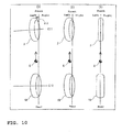
- FIG. 10 illustrates the operation of a conventional motorcycle corresponding to FIG. 8, as a comparative example of the embodiment shown in FIG. 1. Now, with reference to FIGs. 2 and 5 through 10, description is made of the operation during a turn of the motorcycle according to the embodiment and another operation during a turn of the motorcycle according to the comparative example.
- the vehicle body of FIG. 5 is inclined toward the turning direction with respect to the vertical direction, as shown in FIG. 6.
- the head pipe 2 attached to the front wheel 7 rotates with respect to the main frame 3 such that the front wheel 7 moves in the direction of conforming to the bump 100a on the ground 100 (the direction of the arrow A).
- the torsion spring 13 is subjected to torsion and absorbs shock in the direction of conforming to the bump 100a (the direction of the arrow A).
- the motorcycle 1 according to this embodiment is about to make a left turn
- the vehicle body shown in FIG. 8(1) is inclined leftward with respect to the vertical direction, resulting in the front wheel 7 and the rear wheel 10 in the state shown in FIG. 8(2) and FIG. 9.
- the front wheel 7 is steered leftward by a steering angle ⁇ 1 during the left turn.
- the loading direction of the weighted center G does not pass through the torsion axis L1.
- FIG. 11 illustrates the operation of the motorcycle according to the embodiment shown in FIG. 1 while running straight ahead, in which operation the head pipe rotates with respect to the main frame.
- FIG. 12 illustrates the operation of the conventional motorcycle corresponding to FIG. 11, as a comparative example of the embodiment shown in FIG. 1. Now, with reference to FIGs. 2, 11, and 12, description is made of the operation of the motorcycle according to the embodiment while running straight ahead and another operation of the motorcycle according to the comparative example.
- the front wheel 7 of the motorcycle 1 is directed obliquely leftward and forward with respect to the moving direction for some reason, as shown in FIG. 11 (2), while the motorcycle 1 according to this embodiment is running straight ahead as shown in FIG. 11(1).
- the weighted center G of the motorcycle 1 acts straight ahead (forward in FIG. 11 (2)) by inertial force.
- the rear wheel 10 receives force which urges it to rotate outward (rightward) with respect to the front wheel 7 which is directed obliquely leftward and forward.
- the weighted center G of the motorcycle 1 is positioned above the extension line of the torsion axis L1 (see FIG. 2), the main frame 3 (see FIG. 2) and the rear wheel 10 rotate as if to fall outward (leftward) about the torsion axis L1.
- the torsion axis L1 is disposed to extend obliquely rearward and downward from the head pipe 2 as shown in FIG.
- the vehicle is steered rightward by the sympathetic vibration as described above. After steered rightward, the vehicle behaves in the same way as when steered leftward by the steering angle ⁇ 5 as described above and moves straight ahead as the steering angles are converged.
- the head pipe is coupled to the main frame so as not to be rotatable, as a comparative example.
- the front wheel 7 (head pipe) of the motorcycle is directed obliquely leftward and forward, for example, with respect to the moving direction as shown in FIG. 12(2) while the motorcycle is running straight ahead as shown in FIG. 12(1)
- the weighted center G of the motorcycle acts in the direction of running straight ahead (forward in FIG. 12(2)) by inertial force.
- the rear wheel 10 receives force which urges it to be inclined outward (rightward) with respect to the front wheel 7 which is directed obliquely leftward and forward.
- the main frame and the rear wheel 10 rotate as if to fall outward (rightward) about the line connecting the contact point between the front wheel 7 and the ground 100 and the contact point between the rear wheel 10 and the ground 100. Also at this time, since the main frame is coupled to the head pipe so as not to be rotatable, the ground contact point of the front wheel 7 deviates leftward from the center of the vehicle. This causes the driving force of the rear wheel 10 to act on the right side of the contact point between the front wheel 7 and the ground 100, which directs the front wheel 7 further leftward with respect to the moving direction compared to the state shown in FIG. 12(2). This urges the vehicle body to fall further rightward as shown in FIG.
- the main frame and the rear wheel 10 rotate as if to fall outward (leftward) about the line connecting the contact point between the front wheel 7 and the ground 100 and the contact point between the rear wheel 10 and the ground 100. Also at this time, since the main frame is coupled to the head pipe so as not to be rotatable, the contact point of the front wheel 7 with the ground deviates rightward from the center of the vehicle. This causes the driving force of the rear wheel 10 to act on the left side of the contact point between the front wheel 7 and the ground 100, which directs the front wheel 7 further rightward with respect to the moving direction compared to the state shown in FIG. 12(5). This urges the vehicle body to fall further leftward as shown in FIG.
- this embodiment is provided with the main frame 3 to which the head pipe 2 is attached for rotation about the torsion axis L1 of the shaft portion 2a extending longitudinally, and the torsion spring 13 for absorbing shock as the head pipe 2 rotates with respect to the main frame 3.
- the head pipe 2 can be rotated with respect to the main frame 3 such that the front wheel 7 moves in the vehicle width direction to conform to bumps and potholes on the ground 100 during turns with the vehicle body inclined, and the torsion spring 13 can actively absorb shock in the vehicle width direction (lateral direction) with its torsion force during such rotations.
- shock applied in the vehicle width direction (lateral direction) due to bumps and potholes on the ground 100 can be sufficiently absorbed.
- the torsion spring 13 when the front wheel 7 and the rear wheel 10 are in an identical plane, the torsion spring 13 is unloaded (the torsion angle is 0 degrees), and when the front wheel 7 and the rear wheel 10 are not in an identical plane with the head pipe 2 rotated with respect to the main frame 3, the torsion spring 13 is loaded to absorb shock with its torsion force.
- the torsion spring 13 can easily absorb shock with its torsion force when the front wheel 7 and the rear wheel 10 are not in an identical plane with the head pipe 2 rotated with respect to the main frame 3.
- the extension line of the torsion axis L1 of the shaft part 2a extending longitudinally passes near the contact point between the rear wheel 10 and the ground 100.
- This embodiment is provided with the angular bearing 9 for supporting the head pipe 2 and the main frame 3 for rotation with respect to each other.
- the angular bearing 9 allows the head pipe 2 to be smoothly rotated with respect to the main frame 3 about the torsion axis L1 of the shaft part 2a extending longitudinally by means of.
- the angular bearing 9 can also assure the rigidity of the part, where the head pipe 2 and the main frame 3 are coupled, both in the direction along the torsion axis L1 extending longitudinally (thrust direction) and in the direction perpendicular to the torsion axis L1 extending longitudinally (radial direction).
- This embodiment is provided with the pair of stoppers 17 for restricting rotation of the head pipe 2 with respect to the main frame 3, thereby preventing the head pipe 2 from excessively rotating with respect to the main frame 3.
- the engine 22 is mounted to the main frame 3 for supporting the rear wheel 10, and the rear wheel 10 can be inclined, together with the main frame 3 and the engine 22, with respect to the vertical direction during turns.
- the rear wheel 10 since the rear wheel 10 is inclined together with the engine 22 which is heavy, the weighted center G of the vehicle body can be moved leftward and rightward (in the vehicle width direction) with respect to the moving direction easily by inclining the rear wheel 10. This can improve the turning characteristics of the motorcycle 1.
- the above embodiment uses a motorcycle as an example of the vehicle.
- the present teaching is not limited thereto, but is also applicable to other types of vehicles provided with a head pipe and a body frame, such as bicycles, three-wheelers, and ATVs (All Terrain Vehicles).
- the torsion axis of the shaft part of the head pipe extends rearward and downward and passes near the contact point between the rear wheel and the ground.
- the present teaching is not limited thereto, but the torsion axis of the shaft part of the head pipe may extend rearward and downward but not pass near the contact point between the rear wheel and the ground.
- the torsion axis L11 of the shaft part 52a of the head pipe 52 may extend horizontally rearward, and the shaft part 52a of the head pipe 52 and the main frame 53 may be formed such that the torsion spring 13 extends horizontally rearward.
- the above embodiment uses the reciprocating cylinder type damper as an example of the damping means for damping vibration of the torsion spring as the head pipe rotates with respect to the main frame.
- the present teaching is not limited thereto, but a rotary damper which moves in an arc coaxially with the torsion spring may be used.
- the present teaching may not be provided with any member for damping vibration of the torsion spring as the head pipe rotates with respect to the main frame.
- the above embodiment is provided with the torsion spring as an example of the shock absorbing member for absorbing shock as the head pipe rotates with respect to the main frame.
- the present teaching is not limited thereto, but a member other than the torsion spring may be provided as the shock absorbing member for absorbing shock as the head pipe rotates with respect to the main frame.
- the above embodiment uses the angular bearing to support the head pipe and the main frame for rotation with respect to each other.
- the present teaching is not limited thereto, but may use other types of bearings, such as a taper roller bearing, to support the head pipe and the main frame for rotation with respect to each other.
- a vehicle including: a front frame for supporting a front wheel; a rear frame for supporting a rear wheel, to which the front frame is attached for rotation about an axis extending longitudinally; and a shock absorbing member for absorbing shock as the front frame rotates with respect to the rear frame.
- the vehicle according to this embodiment is provided with the rear frame to which the front frame is attached for rotation about the axis extending longitudinally, and the shock absorbing member for absorbing shock as the front frame rotates with respect to the rear frame.
- the front frame can be rotated with respect to the rear frame such that the front wheel moves in the vehicle width direction to conform to bumps and potholes on the ground during turns with the vehicle body inclined, and the shock absorbing member can actively absorb shock in the vehicle width direction (lateral direction) during such rotations.
- shock applied in the vehicle width direction (lateral direction) due to bumps and potholes on the ground can be sufficiently absorbed.
- the shock absorbing member preferably includes a torsion spring disposed between the front frame and the rear frame and on the axis extending longitudinally.
- a front part of the torsion spring is secured to the front frame, and a rear part of the torsion spring is secured to the rear frame.
- the torsion spring is unloaded when the front wheel and the rear wheel are in an identical plane, and the torsion spring is loaded to absorb shock with its torsion force when the front frame and the rear frame are in different planes with the front frame rotated with respect to the rear frame.
- the vehicle according to the embodiments as described above further includes damping means for damping rotation of the front frame with respect to the rear frame.
- damping means for damping rotation of the front frame with respect to the rear frame.
- This structure can converge the vibration in an improved way as the shock absorbing member absorbs shock.
- an extension line of the axis extending longitudinally preferably passes near a contact point between the rear wheel and the ground.
- the vehicle according to the embodiments as described above further includes a bearing for supporting the front frame and the rear frame for rotation with respect to each other, the bearing being disposed between the front frame and the rear frame.
- the bearing allows the front frame to be smoothly rotated with respect to the rear frame about the axis extending longitudinally.
- the bearing is preferably an angular bearing.
- the angular bearing can assure the rigidity of the part, where the front frame and the rear frame are coupled, both in the direction along the axis extending longitudinally (thrust direction) and in the direction perpendicular to the axis extending longitudinally (radial direction).
- the front frame includes a head pipe
- the head pipe includes a first projective bearing attachment part formed to project rearward from the head pipe, the first projective bearing attachment part having a rotation center on the axis extending longitudinally and an outer circumferential surface to which the angular bearing is attached
- the rear frame includes a second recessed bearing attachment part that is disposed to oppose the first projective bearing attachment part of the head pipe and that has an inner circumferential surface to which the angular bearing is attached.
- its weighted center is preferably positioned anywhere other than on the extension line of the axis extending longitudinally.
- the axis extending longitudinally preferably extends rearward and downward of the front frame.
- the rear wheel is inclined about the axis extending downward and rearward (obliquely downward to the rear) and hence the front side of the rear wheel moves rightward slightly more than the rear side thereof. This can reduce the turning radius, thereby improving the turning characteristics.
- the vehicle according to the embodiments as described above further includes a restricting member for restricting rotation of the front frame with respect to the rear frame.
- This structure can prevent the front frame from rotating excessively with respect to the rear frame.
- the vehicle according to the embodiments as described above further includes a front light disposed forward of the front frame, and the front light is secured to the rear frame.
- This structure prevents the front light from rotating with respect to the rear frame and thus allows it to cast light forward of the vehicle body, even when the front frame rotates with respect to the rear frame.
- an engine is mounted to the rear frame for supporting the rear wheel, and the rear wheel can be inclined together with the rear frame and the engine with respect to a vertical direction during a turn.
- the rear wheel since the rear wheel is inclined together with the engine which is heavy, the weighted center of the vehicle body can be moved leftward and rightward (in the vehicle width direction) with respect to the moving direction easily by inclining the rear wheel. This can improve the turning characteristics of the vehicle.
- a vehicle (motorcycle 1) in order to provide a vehicle (motorcycle) capable of sufficiently absorbing shock applied in the vehicle width direction due to bumps and potholes on the ground during turns, includes: a head pipe 2 for supporting a front wheel 7; a main frame 3 for supporting a rear wheel 10, to which the head pipe 2 is attached for rotation about a torsion axis L1 of a shaft part 2a extending longitudinally, and a torsion spring 13 for absorbing shock as the head pipe 2 rotates with respect to the main frame 3.
Landscapes
- Engineering & Computer Science (AREA)
- Mechanical Engineering (AREA)
- Automatic Cycles, And Cycles In General (AREA)
- Axle Suspensions And Sidecars For Cycles (AREA)
- Springs (AREA)
- Vibration Dampers (AREA)
- Body Structure For Vehicles (AREA)
- Seal Device For Vehicle (AREA)
- Pharmaceuticals Containing Other Organic And Inorganic Compounds (AREA)
- Centrifugal Separators (AREA)
Applications Claiming Priority (1)
| Application Number | Priority Date | Filing Date | Title |
|---|---|---|---|
| JP2004364244A JP2006168548A (ja) | 2004-12-16 | 2004-12-16 | 車両 |
Publications (2)
| Publication Number | Publication Date |
|---|---|
| EP1671877A1 true EP1671877A1 (de) | 2006-06-21 |
| EP1671877B1 EP1671877B1 (de) | 2008-02-13 |
Family
ID=35998600
Family Applications (1)
| Application Number | Title | Priority Date | Filing Date |
|---|---|---|---|
| EP05027522A Expired - Lifetime EP1671877B1 (de) | 2004-12-16 | 2005-12-15 | Fahrzeug |
Country Status (5)
| Country | Link |
|---|---|
| US (1) | US7510039B2 (de) |
| EP (1) | EP1671877B1 (de) |
| JP (1) | JP2006168548A (de) |
| AT (1) | ATE385945T1 (de) |
| DE (1) | DE602005004735T2 (de) |
Cited By (5)
| Publication number | Priority date | Publication date | Assignee | Title |
|---|---|---|---|---|
| EP1743831A1 (de) * | 2005-07-12 | 2007-01-17 | Yamaha Hatsudoki Kabushiki Kaisha | Fahrzeug mit lenkbarem Hinterrad |
| EP1783023A1 (de) * | 2005-11-07 | 2007-05-09 | Yamaha Hatsudoki Kabushiki Kaisha | Fahrzeug mit zueinander schwenkbaren Vorder- und Hinterrahmen zum Spurhalten |
| US7490843B2 (en) | 2006-02-06 | 2009-02-17 | Motoczysz Llc | Front end lateral suspension |
| US7832752B2 (en) * | 2006-02-06 | 2010-11-16 | Motoczysz Llc | Front end lateral suspension |
| US10336397B2 (en) * | 2014-12-29 | 2019-07-02 | Peter Tristan Ridet | System and method for dynamic motorcycle frame |
Families Citing this family (4)
| Publication number | Priority date | Publication date | Assignee | Title |
|---|---|---|---|---|
| US7513516B2 (en) * | 2005-08-23 | 2009-04-07 | Jri Development Group, Llc | Shock isolation cradle |
| JP5383411B2 (ja) * | 2009-09-30 | 2014-01-08 | 本田技研工業株式会社 | 鞍乗り型車両のエアバッグ装置 |
| JP5530230B2 (ja) * | 2010-03-16 | 2014-06-25 | 本田技研工業株式会社 | 鞍乗型車両の制振装置 |
| JP2018184117A (ja) * | 2017-04-27 | 2018-11-22 | スズキ株式会社 | オイルコントロールバルブユニットの設置構造及び自動二輪車 |
Citations (4)
| Publication number | Priority date | Publication date | Assignee | Title |
|---|---|---|---|---|
| US3938609A (en) * | 1974-01-28 | 1976-02-17 | Daihatsu Motor Company Limited | Tricycle |
| DE3029373A1 (de) * | 1980-07-31 | 1982-02-11 | Juergen Binder | Motorrad |
| JPS63222987A (ja) | 1987-03-13 | 1988-09-16 | 本田技研工業株式会社 | 自動2輪車 |
| US4984650A (en) * | 1988-03-23 | 1991-01-15 | Honda Giken Kogyo Kabushiki Kaisha | Motorcycle |
Family Cites Families (11)
| Publication number | Priority date | Publication date | Assignee | Title |
|---|---|---|---|---|
| JPS5124048Y2 (de) * | 1973-06-18 | 1976-06-19 | ||
| US4159752A (en) * | 1976-10-14 | 1979-07-03 | Yamaha Hatsudoki Kabushiki Kaisha | Tricycle |
| US4702340A (en) * | 1983-11-17 | 1987-10-27 | Rokon International, Inc. | Motorcycle apparatus |
| JPS61139575A (ja) * | 1984-12-07 | 1986-06-26 | 本田技研工業株式会社 | 揺動型車両の揺動規制装置 |
| JPH01306385A (ja) * | 1988-06-03 | 1989-12-11 | Honda Motor Co Ltd | 自動二輪車 |
| JPH01317885A (ja) * | 1988-06-17 | 1989-12-22 | Honda Motor Co Ltd | 自動二輪車 |
| JPH0268281A (ja) * | 1988-09-05 | 1990-03-07 | Honda Motor Co Ltd | 自動二輪車 |
| AT3646U1 (de) * | 1999-06-17 | 2000-06-26 | Avl List Gmbh | Antriebseinheit für ein motorrad |
| FR2842491B1 (fr) * | 2002-07-19 | 2004-08-27 | Jean Paul Lagar | Dispositif de fixation du train avant sur le chassis d'une motocyclette a angle de chasse et chasse au sol reglables |
| JP4081430B2 (ja) * | 2003-11-19 | 2008-04-23 | 本田技研工業株式会社 | 燃料電池車両 |
| JP4424593B2 (ja) * | 2004-04-27 | 2010-03-03 | 本田技研工業株式会社 | 自動二輪車の排気装置 |
-
2004
- 2004-12-16 JP JP2004364244A patent/JP2006168548A/ja active Pending
-
2005
- 2005-12-13 US US11/302,947 patent/US7510039B2/en not_active Expired - Fee Related
- 2005-12-15 EP EP05027522A patent/EP1671877B1/de not_active Expired - Lifetime
- 2005-12-15 AT AT05027522T patent/ATE385945T1/de not_active IP Right Cessation
- 2005-12-15 DE DE602005004735T patent/DE602005004735T2/de not_active Expired - Fee Related
Patent Citations (4)
| Publication number | Priority date | Publication date | Assignee | Title |
|---|---|---|---|---|
| US3938609A (en) * | 1974-01-28 | 1976-02-17 | Daihatsu Motor Company Limited | Tricycle |
| DE3029373A1 (de) * | 1980-07-31 | 1982-02-11 | Juergen Binder | Motorrad |
| JPS63222987A (ja) | 1987-03-13 | 1988-09-16 | 本田技研工業株式会社 | 自動2輪車 |
| US4984650A (en) * | 1988-03-23 | 1991-01-15 | Honda Giken Kogyo Kabushiki Kaisha | Motorcycle |
Cited By (6)
| Publication number | Priority date | Publication date | Assignee | Title |
|---|---|---|---|---|
| EP1743831A1 (de) * | 2005-07-12 | 2007-01-17 | Yamaha Hatsudoki Kabushiki Kaisha | Fahrzeug mit lenkbarem Hinterrad |
| EP1783023A1 (de) * | 2005-11-07 | 2007-05-09 | Yamaha Hatsudoki Kabushiki Kaisha | Fahrzeug mit zueinander schwenkbaren Vorder- und Hinterrahmen zum Spurhalten |
| US7490843B2 (en) | 2006-02-06 | 2009-02-17 | Motoczysz Llc | Front end lateral suspension |
| US7832752B2 (en) * | 2006-02-06 | 2010-11-16 | Motoczysz Llc | Front end lateral suspension |
| US10336397B2 (en) * | 2014-12-29 | 2019-07-02 | Peter Tristan Ridet | System and method for dynamic motorcycle frame |
| US10597111B2 (en) | 2014-12-29 | 2020-03-24 | Peter Tristan Ridet | System and method for dynamic motorcycle frame |
Also Published As
| Publication number | Publication date |
|---|---|
| JP2006168548A (ja) | 2006-06-29 |
| DE602005004735T2 (de) | 2008-06-05 |
| US20060131092A1 (en) | 2006-06-22 |
| ATE385945T1 (de) | 2008-03-15 |
| EP1671877B1 (de) | 2008-02-13 |
| DE602005004735D1 (de) | 2008-03-27 |
| US7510039B2 (en) | 2009-03-31 |
Similar Documents
| Publication | Publication Date | Title |
|---|---|---|
| US10464632B2 (en) | Straddled vehicle | |
| EP1671877B1 (de) | Fahrzeug | |
| JP2002356189A (ja) | 自動二輪車の車体保護装置 | |
| EP1514786B1 (de) | Lenkungsdämpfer für Fahrzeug, und damit ausgestattetes Fahrzeug | |
| JP2007125917A (ja) | 制御システムおよびそれを備えた自動二輪車 | |
| CN112572662B (zh) | 骑乘式车辆 | |
| US7021642B2 (en) | Steering damper device for two-wheeled vehicle | |
| EP1783023B1 (de) | Fahrzeug mit zueinander schwenkbaren Vorder- und Hinterrahmen zum Spurhalten | |
| JP4254599B2 (ja) | ストラット式サスペンション | |
| JP4786239B2 (ja) | 車両 | |
| EP2500251B1 (de) | Sattelfahrzeug | |
| EP1743831B1 (de) | Fahrzeug mit lenkbarem Hinterrad | |
| JP2007076634A (ja) | 車両 | |
| JP4142279B2 (ja) | 鞍乗り型車両用ステアリングダンパ装置 | |
| KR102563608B1 (ko) | 자동차용 로워암과 너클 간의 체결 장치 | |
| JP2009113679A (ja) | 鞍乗型車両 | |
| KR100792910B1 (ko) | Ctba 트레일링암 부쉬 높이 가변 장치 | |
| JP4927496B2 (ja) | 車両 | |
| JP2007118671A (ja) | 車両 | |
| KR100276704B1 (ko) | 자동차의 언더스티어특성 향상장치 | |
| JP4649367B2 (ja) | 自動二輪車の前輪懸架装置 | |
| JP2009281542A (ja) | フロントフォーク及び該フロントフォークを備えた自動二輪車 | |
| KR20080036793A (ko) | 차량 현가장치의 스트러트 구조 | |
| JP2019156037A (ja) | 自動二輪車の走行安定構造 |
Legal Events
| Date | Code | Title | Description |
|---|---|---|---|
| PUAI | Public reference made under article 153(3) epc to a published international application that has entered the european phase |
Free format text: ORIGINAL CODE: 0009012 |
|
| AK | Designated contracting states |
Kind code of ref document: A1 Designated state(s): AT BE BG CH CY CZ DE DK EE ES FI FR GB GR HU IE IS IT LI LT LU LV MC NL PL PT RO SE SI SK TR |
|
| AX | Request for extension of the european patent |
Extension state: AL BA HR MK YU |
|
| 17P | Request for examination filed |
Effective date: 20060512 |
|
| 17Q | First examination report despatched |
Effective date: 20060728 |
|
| AKX | Designation fees paid |
Designated state(s): AT BE BG CH CY CZ DE DK EE ES FI FR GB GR HU IE IS IT LI LT LU LV MC NL PL PT RO SE SI SK TR |
|
| GRAP | Despatch of communication of intention to grant a patent |
Free format text: ORIGINAL CODE: EPIDOSNIGR1 |
|
| GRAS | Grant fee paid |
Free format text: ORIGINAL CODE: EPIDOSNIGR3 |
|
| GRAA | (expected) grant |
Free format text: ORIGINAL CODE: 0009210 |
|
| AK | Designated contracting states |
Kind code of ref document: B1 Designated state(s): AT BE BG CH CY CZ DE DK EE ES FI FR GB GR HU IE IS IT LI LT LU LV MC NL PL PT RO SE SI SK TR |
|
| REG | Reference to a national code |
Ref country code: GB Ref legal event code: FG4D |
|
| REG | Reference to a national code |
Ref country code: CH Ref legal event code: EP |
|
| REG | Reference to a national code |
Ref country code: IE Ref legal event code: FG4D |
|
| REF | Corresponds to: |
Ref document number: 602005004735 Country of ref document: DE Date of ref document: 20080327 Kind code of ref document: P |
|
| PG25 | Lapsed in a contracting state [announced via postgrant information from national office to epo] |
Ref country code: IS Free format text: LAPSE BECAUSE OF FAILURE TO SUBMIT A TRANSLATION OF THE DESCRIPTION OR TO PAY THE FEE WITHIN THE PRESCRIBED TIME-LIMIT Effective date: 20080613 Ref country code: ES Free format text: LAPSE BECAUSE OF FAILURE TO SUBMIT A TRANSLATION OF THE DESCRIPTION OR TO PAY THE FEE WITHIN THE PRESCRIBED TIME-LIMIT Effective date: 20080524 Ref country code: FI Free format text: LAPSE BECAUSE OF FAILURE TO SUBMIT A TRANSLATION OF THE DESCRIPTION OR TO PAY THE FEE WITHIN THE PRESCRIBED TIME-LIMIT Effective date: 20080213 |
|
| NLV1 | Nl: lapsed or annulled due to failure to fulfill the requirements of art. 29p and 29m of the patents act | ||
| PG25 | Lapsed in a contracting state [announced via postgrant information from national office to epo] |
Ref country code: BE Free format text: LAPSE BECAUSE OF FAILURE TO SUBMIT A TRANSLATION OF THE DESCRIPTION OR TO PAY THE FEE WITHIN THE PRESCRIBED TIME-LIMIT Effective date: 20080213 Ref country code: SI Free format text: LAPSE BECAUSE OF FAILURE TO SUBMIT A TRANSLATION OF THE DESCRIPTION OR TO PAY THE FEE WITHIN THE PRESCRIBED TIME-LIMIT Effective date: 20080213 Ref country code: LV Free format text: LAPSE BECAUSE OF FAILURE TO SUBMIT A TRANSLATION OF THE DESCRIPTION OR TO PAY THE FEE WITHIN THE PRESCRIBED TIME-LIMIT Effective date: 20080213 Ref country code: PL Free format text: LAPSE BECAUSE OF FAILURE TO SUBMIT A TRANSLATION OF THE DESCRIPTION OR TO PAY THE FEE WITHIN THE PRESCRIBED TIME-LIMIT Effective date: 20080213 |
|
| PG25 | Lapsed in a contracting state [announced via postgrant information from national office to epo] |
Ref country code: CZ Free format text: LAPSE BECAUSE OF FAILURE TO SUBMIT A TRANSLATION OF THE DESCRIPTION OR TO PAY THE FEE WITHIN THE PRESCRIBED TIME-LIMIT Effective date: 20080213 Ref country code: PT Free format text: LAPSE BECAUSE OF FAILURE TO SUBMIT A TRANSLATION OF THE DESCRIPTION OR TO PAY THE FEE WITHIN THE PRESCRIBED TIME-LIMIT Effective date: 20080714 Ref country code: DK Free format text: LAPSE BECAUSE OF FAILURE TO SUBMIT A TRANSLATION OF THE DESCRIPTION OR TO PAY THE FEE WITHIN THE PRESCRIBED TIME-LIMIT Effective date: 20080213 Ref country code: SE Free format text: LAPSE BECAUSE OF FAILURE TO SUBMIT A TRANSLATION OF THE DESCRIPTION OR TO PAY THE FEE WITHIN THE PRESCRIBED TIME-LIMIT Effective date: 20080513 Ref country code: NL Free format text: LAPSE BECAUSE OF FAILURE TO SUBMIT A TRANSLATION OF THE DESCRIPTION OR TO PAY THE FEE WITHIN THE PRESCRIBED TIME-LIMIT Effective date: 20080213 Ref country code: SK Free format text: LAPSE BECAUSE OF FAILURE TO SUBMIT A TRANSLATION OF THE DESCRIPTION OR TO PAY THE FEE WITHIN THE PRESCRIBED TIME-LIMIT Effective date: 20080213 |
|
| PG25 | Lapsed in a contracting state [announced via postgrant information from national office to epo] |
Ref country code: RO Free format text: LAPSE BECAUSE OF FAILURE TO SUBMIT A TRANSLATION OF THE DESCRIPTION OR TO PAY THE FEE WITHIN THE PRESCRIBED TIME-LIMIT Effective date: 20080213 |
|
| EN | Fr: translation not filed | ||
| PLBE | No opposition filed within time limit |
Free format text: ORIGINAL CODE: 0009261 |
|
| STAA | Information on the status of an ep patent application or granted ep patent |
Free format text: STATUS: NO OPPOSITION FILED WITHIN TIME LIMIT |
|
| 26N | No opposition filed |
Effective date: 20081114 |
|
| PG25 | Lapsed in a contracting state [announced via postgrant information from national office to epo] |
Ref country code: LT Free format text: LAPSE BECAUSE OF FAILURE TO SUBMIT A TRANSLATION OF THE DESCRIPTION OR TO PAY THE FEE WITHIN THE PRESCRIBED TIME-LIMIT Effective date: 20080213 |
|
| PGFP | Annual fee paid to national office [announced via postgrant information from national office to epo] |
Ref country code: AT Payment date: 20081211 Year of fee payment: 4 |
|
| PG25 | Lapsed in a contracting state [announced via postgrant information from national office to epo] |
Ref country code: EE Free format text: LAPSE BECAUSE OF FAILURE TO SUBMIT A TRANSLATION OF THE DESCRIPTION OR TO PAY THE FEE WITHIN THE PRESCRIBED TIME-LIMIT Effective date: 20080213 Ref country code: FR Free format text: LAPSE BECAUSE OF FAILURE TO SUBMIT A TRANSLATION OF THE DESCRIPTION OR TO PAY THE FEE WITHIN THE PRESCRIBED TIME-LIMIT Effective date: 20081205 Ref country code: BG Free format text: LAPSE BECAUSE OF FAILURE TO SUBMIT A TRANSLATION OF THE DESCRIPTION OR TO PAY THE FEE WITHIN THE PRESCRIBED TIME-LIMIT Effective date: 20080513 |
|
| PGFP | Annual fee paid to national office [announced via postgrant information from national office to epo] |
Ref country code: DE Payment date: 20081211 Year of fee payment: 4 |
|
| PG25 | Lapsed in a contracting state [announced via postgrant information from national office to epo] |
Ref country code: MC Free format text: LAPSE BECAUSE OF NON-PAYMENT OF DUE FEES Effective date: 20081231 Ref country code: CY Free format text: LAPSE BECAUSE OF FAILURE TO SUBMIT A TRANSLATION OF THE DESCRIPTION OR TO PAY THE FEE WITHIN THE PRESCRIBED TIME-LIMIT Effective date: 20080213 |
|
| PG25 | Lapsed in a contracting state [announced via postgrant information from national office to epo] |
Ref country code: IE Free format text: LAPSE BECAUSE OF NON-PAYMENT OF DUE FEES Effective date: 20081215 |
|
| PG25 | Lapsed in a contracting state [announced via postgrant information from national office to epo] |
Ref country code: HU Free format text: LAPSE BECAUSE OF FAILURE TO SUBMIT A TRANSLATION OF THE DESCRIPTION OR TO PAY THE FEE WITHIN THE PRESCRIBED TIME-LIMIT Effective date: 20080814 Ref country code: LU Free format text: LAPSE BECAUSE OF NON-PAYMENT OF DUE FEES Effective date: 20081215 |
|
| REG | Reference to a national code |
Ref country code: CH Ref legal event code: PL |
|
| GBPC | Gb: european patent ceased through non-payment of renewal fee |
Effective date: 20091215 |
|
| PG25 | Lapsed in a contracting state [announced via postgrant information from national office to epo] |
Ref country code: AT Free format text: LAPSE BECAUSE OF NON-PAYMENT OF DUE FEES Effective date: 20091215 Ref country code: TR Free format text: LAPSE BECAUSE OF FAILURE TO SUBMIT A TRANSLATION OF THE DESCRIPTION OR TO PAY THE FEE WITHIN THE PRESCRIBED TIME-LIMIT Effective date: 20080213 |
|
| PG25 | Lapsed in a contracting state [announced via postgrant information from national office to epo] |
Ref country code: CH Free format text: LAPSE BECAUSE OF NON-PAYMENT OF DUE FEES Effective date: 20091231 Ref country code: GR Free format text: LAPSE BECAUSE OF FAILURE TO SUBMIT A TRANSLATION OF THE DESCRIPTION OR TO PAY THE FEE WITHIN THE PRESCRIBED TIME-LIMIT Effective date: 20080514 Ref country code: LI Free format text: LAPSE BECAUSE OF NON-PAYMENT OF DUE FEES Effective date: 20091231 |
|
| PG25 | Lapsed in a contracting state [announced via postgrant information from national office to epo] |
Ref country code: DE Free format text: LAPSE BECAUSE OF NON-PAYMENT OF DUE FEES Effective date: 20100701 |
|
| PG25 | Lapsed in a contracting state [announced via postgrant information from national office to epo] |
Ref country code: GB Free format text: LAPSE BECAUSE OF NON-PAYMENT OF DUE FEES Effective date: 20091215 |
|
| PGFP | Annual fee paid to national office [announced via postgrant information from national office to epo] |
Ref country code: IT Payment date: 20081231 Year of fee payment: 4 |