EP1672084B1 - Procédé et dispositif pour traiter automatiquement des pièces non-métalliques flexibles - Google Patents
Procédé et dispositif pour traiter automatiquement des pièces non-métalliques flexibles Download PDFInfo
- Publication number
- EP1672084B1 EP1672084B1 EP05023384A EP05023384A EP1672084B1 EP 1672084 B1 EP1672084 B1 EP 1672084B1 EP 05023384 A EP05023384 A EP 05023384A EP 05023384 A EP05023384 A EP 05023384A EP 1672084 B1 EP1672084 B1 EP 1672084B1
- Authority
- EP
- European Patent Office
- Prior art keywords
- workpieces
- knife
- scarfing
- workpiece
- station
- Prior art date
- Legal status (The legal status is an assumption and is not a legal conclusion. Google has not performed a legal analysis and makes no representation as to the accuracy of the status listed.)
- Expired - Lifetime
Links
Images

Classifications
-
- C—CHEMISTRY; METALLURGY
- C14—SKINS; HIDES; PELTS; LEATHER
- C14B—MECHANICAL TREATMENT OR PROCESSING OF SKINS, HIDES OR LEATHER IN GENERAL; PELT-SHEARING MACHINES; INTESTINE-SPLITTING MACHINES
- C14B5/00—Clicking, perforating, or cutting leather
-
- A—HUMAN NECESSITIES
- A43—FOOTWEAR
- A43D—MACHINES, TOOLS, EQUIPMENT OR METHODS FOR MANUFACTURING OR REPAIRING FOOTWEAR
- A43D8/00—Machines for cutting, ornamenting, marking or otherwise working up shoe part blanks
- A43D8/32—Working on edges or margins
-
- A—HUMAN NECESSITIES
- A43—FOOTWEAR
- A43D—MACHINES, TOOLS, EQUIPMENT OR METHODS FOR MANUFACTURING OR REPAIRING FOOTWEAR
- A43D8/00—Machines for cutting, ornamenting, marking or otherwise working up shoe part blanks
- A43D8/46—Splitting
- A43D8/48—Splitting combined with skiving
Definitions
- the invention relates to a method and a device for the automatic processing of non-metallic, yielding workpieces.
- bell knives are common, such as from DE 198 58 619 C1 , of the DE 199 29 977 C1 and the DE 35 36 220 C2 known.
- the bell-shaped blade is arranged stationary in the respective device and is driven in rotation.
- the respective operator now has to guide the flap-like workpiece along the bell-shaped knife in order to either separate it (split) or to cut it (sharpen) at the edge in a suitable manner.
- the disadvantage of such an arrangement is of course the high manual effort, which is created by the targeted Entangenirriate the workpiece on the bell.
- the workpieces are first cut to the desired size and shape at one or more cutting stations and then sharpened at one or more sharpening stations as described above.
- a material to be sharpened is guided along a stop with the aid of a feed roller against a rotating bell-shaped knife and thus cut or sharpened on its surface.
- a machine for cutting flap-like workpieces in which a housing-fixed and immovable arm is provided, on which a horizontal axis is mounted for a swivel head, wherein a disc knife is provided for cutting the workpieces, and wherein above the plate knife provided a guide member is, which is arranged by means of a holder and a centering ring on the swivel head.
- Such a device using a plate knife is not suitable for semi-automatic or automatic sharpening of a flap-like workpiece.
- the invention is thus based on the object to provide a method and an apparatus for processing non-metallic, resilient workpieces, whereby a simplified machining of workpieces is possible.
- This object is achieved by a method for processing non-metallic, yielding workpieces, in which the workpieces are first sharpened by means of a bell knife or band knife and then cut.
- the cohesion of the material enables semi-automatic or automatic processing.
- the object is achieved by the sharpening by means of a motor-driven knife in the form of a bell knife or band blade, the material lying on the plan to be sharpened material from above to be led.
- the sharpening process can then be followed by a preferably automatic cutting process.
- the material to be sharpened is depressed in the area of the knife which is not to be sharpened.
- the knife is preferably guided automatically controlled during the sharpening process.
- the workpieces of endless material (such as roll material) are produced, which is first sharpened, and from which the workpieces are separated by a subsequent cutting process.
- the automatic machining is greatly simplified because the positioning of the workpieces is determined by the cohesion of the continuous material for the subsequent cutting process. This can be costly positioning omitted if necessary.
- the workpieces are first sharpened and provided with markings. These marks are used to control a subsequent cutting operation.
- the material is held on the substrate during the sharpening process by means of vacuum assistance.
- a pressing force of the workpiece which is increased in relation to the other areas of the workpiece, is also produced on its base, which can be achieved in a relatively simple manner when using a vacuum table.
- the object of the invention is achieved by a device for machining non-metallic, compliant workpieces, with at least one sharpening station for sharpening the workpieces, which has a motor-driven knife in the form of a bell knife, and a receiving table for supporting a workpiece, wherein the Knife is guided automatically movable at a sharpening unit above the receiving table and means are provided for holding down the workpiece on the support surface in the region of the knife.
- the means for holding down the workpiece preferably comprise a hold-down in order to press the material to be processed in the region of the knife.
- the hold-down device here are preferably associated adjusting means for adjusting its relative position with respect to the bell-type meter.
- the support surface of the vacuum table is divided into a plurality of zones whose suction power is controllable in dependence on the position of the cutting unit.
- the zone in the area where the cutting unit is currently located can be operated with an increased suction power, so as to achieve a particularly strong holddown of the workpiece in the region of the cutting unit, so that a deflection of the workpiece relative to the knife is avoided.
- the vacuum table has a basic vacuum zone, with a first pressure difference which extends over a larger area of the support surface, and a movable vacuum zone which extends over a smaller area below the cutting unit, whose position is dependent on the Position of the cutting unit is locally controllable, and having a greater pressure difference than the first pressure difference.
- valves can be provided for controlling the movable vacuum zone, which valves can be controlled mechanically or electronically as a function of the position of the cutting unit.
- a mechanical control of the valves could, for example, be achieved by running along with the cutting unit below the support surface as a bar, of which the valves are actuated as about a Kipphebel strictlyung.
- valves are formed as solenoid valves, which are controlled by an electronic control unit, which also controls the movement of the cutting unit. This is of course associated with significantly less mechanical effort than with a mechanical control.
- the support surface of the vacuum table is penetrated by a plurality of suction openings, which are preferably arranged in a grid.
- the suction openings are preferably arranged in a square grid, wherein the grid spacing between adjacent suction openings at most 15 millimeters, preferably at most 10 millimeters, more preferably less than 10 millimeters, for example. Be about 5 millimeters.
- the suction openings have a diameter of less than 1 millimeter, preferably less than 0.8 millimeter, for example. About 0.5 millimeters, on.
- the suction effect of the vacuum table can be improved or adapted so that even very flexible workpieces can be sucked with sufficient precision to avoid deflection of the workpiece in the region of the cutting point.
- an outflow opening for the outflow of compressed air in the direction of the workpiece is further provided in the region of the hold-down.
- This measure supports a holddown of the workpiece in the region of the interface, whereby a deflection of the workpiece is further counteracted.
- the cutting unit is in a preferred embodiment of the invention by means of an electronic control unit in three linear axes and automatically controlled to control a rotational axis.
- the sharpening station has marking means for producing markings on the workpieces.
- a respective downstream cutting station can then be made with associated sensor means a correct positioning of the workpieces.
- the marking agents may be agents which are generally known in the art, such as a marking device by means of an ink-jet printing technique or by means of laser technology.
- Such markings may be omitted if continuous material (e.g., roll stock) is processed. This is therefore particularly preferred.
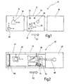
- a device according to the invention is shown and designated overall by the numeral 10.
- the apparatus 10 includes a sharpening station 12 followed by a cutting station 14 and a removal station 16.
- Raw material appropriately controlled to its quality is first fed to the sharpening station 12 where it is mounted on a level surface and sharpened by means of a sharpening unit 18 which is automatically guided and positioned.
- the sharpening unit 18 can be controlled and positioned in the x-direction and Y-direction.
- the raw material is compliant workpieces, such as flap-like workpieces, such as leather, synthetic leather, paper, cardboard or the like.
- the sharpening is done in full on a hard, level surface, without the material is completely severed.
- the sharpening station 12 has a marking unit 20.
- This may be, for example, an intelligent inkjet marking unit, which is also in the x-direction and y-direction controlled to be moved to apply on the workpieces markings at appropriate positions, which allow precise positioning of the workpieces in the downstream cutting station 14.
- the workpieces are preferably automatically transferred by means of a suitable transport device in the direction of the arrow 32 to the downstream cutting station 14 and then automatically positioned by means of suitable sensor means 31 using the previously applied markings.
- suitable sensor means 31 By way of example, four markings 22, 24, 26, 28 are indicated here, which can be read out by means of a movable sensor means 31. These markings are then used to position correction in the leadership of a cutting unit 30 in an automatic cutting process.
- the cutting unit 30 may be, for example, a laser cutting unit, a water jet cutting unit, a knife cutting unit, or any other cutting unit generally known in the art. If a knife cutting unit is used, a resilient flat bearing surface is used.
- the cutting process produces individual workpieces which are completely automatically processed and which are removed and provided automatically or by hand at the downstream removal station 16 for further processing or for further transport.
- Fig. 2 is a variant of the embodiment according to Fig. 1 represented and designated overall by the numeral 40.
- the device comprises a sharpening station 42, to which in Direction 62 of the material flow a cutting station 44 and a removal station 46 connect.
- FIG. 2 some workpieces 64 are shown, which are separated from each other during the cutting process at the cutting station and then removed, for example by means of a handling device 68 of the removal station 46, for example by means of a suction device 70.
- a sharpening station according to the invention is designated overall by the numeral 112.
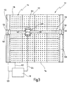
- the sharpening station has a vacuum table 110, the bearing surface 114 of which is provided with a plurality of suction openings 116, which in the example shown are arranged in a square grid.
- the vacuum table 110 serves to support and fix the workpieces.
- Fig. 3 For sharpening the workpieces is an in Fig. 3 provided in total with the numeral 126 indicated sharpening unit, which is equipped with a bell knife 148 (see. Fig. 4 ).
- the sharpening unit 126 is automatically guided guided in three coordinate directions (x, y, z) and additionally pivotable about an axis of rotation (r).
- a respective linear guide 128 or 132 is provided, which is arranged parallel to one another, on which slides 130 and 134 are guided.
- the two carriages 130, 134 are connected by a beam, which is likewise designed again as a linear guide 136 for a further slide 138.
- At least one of the two carriages 130, 134 can be driven by a motor, so that both carriages 130, 134 move synchronously, as indicated by the double arrows 140.
- the carriage 138 On the linear guide 136 between the two carriages 130, 134, the carriage 138 is in turn controlled in the direction of the double arrow 142 along the linear guide 136 movable.
- a further linear guide in the vertical direction (z-direction) is added, on which the sharpening unit 126 is held, which is additionally pivotable about an axis of rotation, as indicated by the double arrow 144.
- an automatic control unit 118 is provided, which is preferably a microprocessor-controlled unit which is programmable.
- a microprocessor-controlled unit which is programmable.
- it could be a PLC controller.
- Fig. 3 is indicated schematically that the control unit 118 is connected via lines 120, 124 with the drives for automatic positioning and also via a control line 122 to the vacuum table 110, in order to change the suction power of the vacuum table 110 can locally targeted in the manner described below.
- the support surface 114 of the vacuum table 110 is penetrated by a plurality of suction openings 116, which are arranged in a square grid.
- the distance a between adjacent suction openings 116 for example, be about 8 millimeters, while the diameter d of the suction openings 116, for example. 0.7 millimeters is (the drawing according to Fig. 4 is not necessarily to scale, but merely demonstrates the geometric relationships).
- the bearing surface 114 of the vacuum table 110 is, as in Fig. 3 indicated by dividing lines, divided into a total of sixteen square zones q ik .
- each zone q ik by suitable partitions 166 airtight to adjacent zones and after closed down, so that in each case a suction chamber is formed.
- a suction chamber belonging to the zone q 12 is designated by the numeral 167.
- each zone q ik can be acted upon together with a certain negative pressure, while the other zones can be operated with a different negative pressure (the dividing lines in Fig. 3 indicate only the schematic division of the entire bearing surface 114 in the different zones; Partitions between adjacent zones preferably do not extend through suction openings, but conveniently between adjacent suction openings, as in FIG Fig. 4 shown).
- the zone q 12 is connected via a first valve 168 with a line 180 to a first vacuum pump 182 and further connected via a second valve 170 and a line 176 to a second vacuum pump 178.
- the remaining zones are each connected via two valves to the first and second vacuum pump.
- the adjacent zone q 22 is connected via a valve 172 to the vacuum pump 182 and connected via a valve 174 to the vacuum pump 178.
- the suction power of all sixteen zones q ik can be controlled in a targeted manner.
- this is done so that the zone above which the sharpening unit 126 is currently located, is operated with an increased suction power, while all other zones are operated with a lower suction power.
- the solenoid valve 170 which is connected to the vacuum pump 178, while all other solenoid valves connected to this vacuum pump 178 are closed.
- the other solenoid valve 168 connected to the vacuum pump 182 is closed, while all the remaining solenoid valves of the other zones connected to this vacuum pump 182 are opened.
- the control of the solenoid valves preferably takes place via the automatic control unit 118 as a function of the (known) position of the sharpening unit 126.
- the individual zones q ik can also be made smaller in order to allow a more targeted adaptation of the increased suction power as a function of the position of the sharpening unit 126.
- the sharpening unit 126 is different from conventional sharpening units according to the DE 198 58 619 Cl or the DE 199 29 977 C1 designed so that the sharpening is done on a flat support surface, and that the knife is guided in the form of a bell knife 148 from above the material to be sharpened along.
- the flat bearing surface assumes the function of the curved in the prior art guide foot.
- the sharpening shape is generated by one or more hold-down.
- two mirror-symmetrically arranged hold-downs 156, 157 are provided.
- the hold-downs 156, 157 are basically compressing elements that are designed as foot or roller-shaped elements.
- the material is compressed to produce the desired sharpening shape. Since the sharpening is done in full, the elastic material is sharpened in the effective range of the bell blade 148 just where it is not depressed by the downers 156, 157. Because it stands out there and is cut or sharpened by the bell knife.
- each hold-down device can, as indicated by adjusting means 155, be adjusted in their relative position to the bell knife 148.
- each hold-down device is additionally suitably adjustable (for example by a prismatic guide) in the vertical direction in order to be able to adjust automatically the setting height of the hold-down device, depending on the respective parameters.
- the sharpening unit 126 has a base plate 146 which is held at the lower end of a vertical rod 145.
- the rod 145 can be moved in a manner not shown in the vertical direction (z-direction) controlled by a certain amount, as indicated by the double arrow 188. Further, the rod 145 can be pivoted about its longitudinal axis 185 by a certain angular amount, as indicated by the arrow 186.
- a knife 148 On the base plate 146 is a knife 148, which is designed as a bell knife, by means of a not shown Drive rotationally driven, as indicated by the arrow 150.
- a grinding unit may be provided laterally on the base plate 146 with a grinding wheel 152 which is driven by a drive 154 and which is delivered to the rotary knife 148 as needed, as indicated by the double arrow 153, to sharpen and / or adhere it Clean dirt particles.
- a compressed air line 60 is coupled via a screw 158 to the hold-down device 156.
- outlet openings 159 are provided, is blown through the supplied compressed air in the area on the interface to additionally hold down the workpiece 164 in the area of the interface.
- only one compressed air line 160 is shown for the hold-down 156, it is understood that preferably also the other hold-down 157 is coupled to a compressed air line to supply compressed air via outflow openings.
- Fig. 4 is on the grinding wheel 152 opposite side additionally below the base plate 146 nor a cover 162 shown, which serves as Berbuildstoff in the area of the bell blade 148.
- All supply lines can, as in Fig. 4 indicated schematically, be led away in a common supply line 184 up to a suspension on which the rod 145 is held.
- automatic sharpening and cutting of workpieces is made possible. It can on the one hand lobe-like Workpieces, such as. Leather pieces are processed.
- compliant endless material, such as roll material can be processed in order to produce in a particularly simple and cost-effective manner, for example, artificial leather pieces, such as are needed as a reference for dashboards, automatically.
Landscapes
- Engineering & Computer Science (AREA)
- Mechanical Engineering (AREA)
- Chemical & Material Sciences (AREA)
- Organic Chemistry (AREA)
- Treatment Of Fiber Materials (AREA)
- Laser Beam Processing (AREA)
- Turning (AREA)
- Electrical Discharge Machining, Electrochemical Machining, And Combined Machining (AREA)
Claims (20)
- Procédé pour traiter des pièces non-métalliques, flexibles (64 ; 164), caractérisé en ce que les pièces (64 ; 164) sont d'abord rectifiées à l'aide d'une lame cloche ou d'une lame ruban puis coupées.
- Procédé selon la revendication 1, dans le cadre duquel la rectification des pièces (64 ; 164) se fait entièrement sur un support plan.
- Procédé pour traiter des pièces non-métalliques, flexibles (64 ; 164), en particulier selon la revendication 1 ou 2, dans le cadre duquel la rectification se fait au moyen d'une lame (148) entraînée par moteur, prenant la forme d'une lame cloche ou d'une lame ruban, qui est conduite par le haut le long du matériau (66) à rectifier à plat.
- Procédé selon la revendication 3, dans le cadre duquel le matériau à rectifier est enfoncé dans la zone de la lame (148) à ne pas rectifier.
- Procédé selon la revendication 3 ou 4, dans le cadre duquel la lame (148) est guidée par commande automatique pendant l'opération de rectification.
- Procédé selon l'une quelconque des revendications 2 à 5, dans le cadre duquel les pièces (64 ; 164) en matériau continu (66), qui est d'abord rectifié, sont découpées par une opération de coupe ultérieure.
- Procédé selon la revendication 2, 3, 4, 5, ou 6, dans lequel les pièces (64 ; 164) sont d'abord rectifiées et dotées de marquages, qui sont utilisés pour la commande d'une opération de coupe ultérieure.
- Procédé selon l'une quelconque des revendications précédentes, caractérisé en ce que le matériau est maintenu sur un support par vide pendant l'opération de rectification.
- Procédé selon la revendication 8, dans le cadre duquel dans la zone de l'opération de rectification, un effort d'application de la pièce (64 ; 164), accru par rapport aux autres zones de la pièce (64 ; 164), est généré au niveau de son support.
- Dispositif pour traiter des pièces non-métalliques, flexibles (64 ; 164), avec au moins une station de rectification (12 ; 42 ; 112) servant à rectifier les pièces (64 ; 164), avec une lame (148) entraînée par moteur prenant la forme d'une lame cloche et avec une table de réception (110) servant à la pose d'une pièce (64 ; 164), caractérisé en ce que la lame (148) est guidée par déplacement automatique au niveau d'une unité de rectification (18 ; 48 ; 126) au-dessus de la table de réception (110) et des moyens de maintien de la pièce (64 ; 164) sur la surface d'appui (114) sont prévus dans la zone de la lame (148).
- Dispositif selon la revendication 10, caractérisé par au moins une station de coupe (14 ; 44) servant à couper les pièces (64 ; 164), la station de coupe (14 ; 44) étant placée en aval de la station de rectification (12 ; 42 ; 112) dans le sens de transport (32 ; 62) des pièces (64 ; 164).
- Dispositif selon la revendication 10 ou 11, caractérisé en ce que l'unité de rectification (18 ; 48 ; 126) est mobile par guidage automatique au moins dans un plan (x, y) parallèlement à une surface d'appui (114) de la table à vide (110).
- Dispositif selon la revendication 10, 11 ou 12, caractérisé en ce que la table de réception est réalisée sous forme de table à vide (110), qui présente une surface d'appui (114), qui est divisée en une pluralité de zones (qik), dont la puissance d'aspiration peut être commandée en fonction de la position de l'unité de rectification (18 ; 48 ; 126).
- Dispositif selon la revendication 13, caractérisé en ce que la table à vide (110) présente une zone de vide de base, avec une première différence de pression, qui s'étend sur une grande zone de la surface d'appui, et présente une zone de vide mobile (qik), qui s'étend sur une petite zone sous l'unité de rectification (18 ; 48 ; 126), dont la position peut être commandée localement en fonction de la position de l'unité de rectification (18 ; 48 ; 126) et qui présente une différence de pression supérieure à la première différence de pression.
- Dispositif selon la revendication 13 ou 14, caractérisé en ce que des soupapes (168, 170, 172, 174) sont prévues pour la commande de la zone de vide mobile (qik), lesquelles peuvent être commandées par voie mécanique ou électronique en fonction de la position de l'unité de rectification (18 ; 48 ; 126).
- Dispositif selon la revendication 15, dans lequel des moyens de positionnement (155, 161) sont associés à l'élément de retenue (156, 157) pour le réglage de sa position relative par rapport à la lame cloche (148).
- Dispositif selon l'une quelconque des revendications 10 à 16, caractérisé en ce que des orifices d'évacuation (159) sont prévus dans la zone de l'élément de retenue (156, 161) pour l'évacuation d'air comprimé sur la pièce (64 ; 164).
- Dispositif selon l'une quelconque des revendications 10 à 17, caractérisé en ce que l'unité de rectification (18 ; 48 ; 126) peut être déplacée par commande automatique selon trois axes linéaires (x, y, z) et autour d'un axe de rotation (r) à l'aide d'une unité de commande électronique (118).
- Dispositif selon l'une quelconque des revendications 10 à 18, caractérisé en ce que la station de rectification (12) présente des moyens de marquage permettant de produire des marquages sur les pièces.
- Dispositif selon l'une quelconque des revendications 11 à 19, caractérisé en ce que la station de coupe (14) présente des moyens de détection (31) qui sont réalisés pour détecter des marquages (22, 24, 26, 28) produits dans la station de rectification (12).
Applications Claiming Priority (1)
| Application Number | Priority Date | Filing Date | Title |
|---|---|---|---|
| DE102004062374A DE102004062374B4 (de) | 2004-12-14 | 2004-12-14 | Verfahren und Vorrichtung zum automatischen Bearbeiten von nichtmetallischen, nachgiebigen Werkstücken |
Publications (2)
| Publication Number | Publication Date |
|---|---|
| EP1672084A1 EP1672084A1 (fr) | 2006-06-21 |
| EP1672084B1 true EP1672084B1 (fr) | 2009-10-21 |
Family
ID=35810088
Family Applications (1)
| Application Number | Title | Priority Date | Filing Date |
|---|---|---|---|
| EP05023384A Expired - Lifetime EP1672084B1 (fr) | 2004-12-14 | 2005-10-26 | Procédé et dispositif pour traiter automatiquement des pièces non-métalliques flexibles |
Country Status (3)
| Country | Link |
|---|---|
| EP (1) | EP1672084B1 (fr) |
| AT (1) | ATE446390T1 (fr) |
| DE (2) | DE102004062374B4 (fr) |
Families Citing this family (3)
| Publication number | Priority date | Publication date | Assignee | Title |
|---|---|---|---|---|
| DE102015107438A1 (de) * | 2015-05-12 | 2016-11-17 | Fortuna Spezialmaschinen Gmbh | Vorrichtung und Verfahren zum Schärfen von Zuschnitten aus biegeschlaffem Material |
| DE102015107437A1 (de) * | 2015-05-12 | 2016-11-17 | Fortuna Spezialmaschinen Gmbh | Vorrichtung und Verfahren zum Spalten von Zuschnitten aus biegeschlaffem Material |
| CN108272175A (zh) * | 2018-03-28 | 2018-07-13 | 广安捷米科技有限公司 | 港宝加工设备及加工方法 |
Family Cites Families (8)
| Publication number | Priority date | Publication date | Assignee | Title |
|---|---|---|---|---|
| DE1250960B (de) | 1967-09-28 | Fortuna Werke Maschinenfabrik Aktiengesellschaft, Stuttgart-Bad Cannstatt | Emschneidemaschme | |
| US3088353A (en) * | 1959-03-23 | 1963-05-07 | Scholl Mfg Co Inc | Mechanism for and method of producing surgical pads |
| DE3536220A1 (de) * | 1985-10-10 | 1987-04-16 | Fortuna Werke Maschf Ag | Verfahren zum fuehren von werkstuecken an schaerfmaschinen und fuehrungsvorrichtung zur durchfuehrung des verfahrens |
| DE3544251A1 (de) * | 1985-12-14 | 1987-06-19 | Duerkopp System Technik Gmbh | Verfahren und vorrichtung zum selbsttaetigen zuschneiden von teilen aus flaechigem naehgut nach mit unterschiedlichen konturen versehenen mustervorlagen auf einer koordinaten-schneidmaschine |
| DE3732059A1 (de) | 1987-09-23 | 1989-04-06 | Fortuna Werke Maschf Ag | Schaerfmaschine |
| EP0707079A1 (fr) * | 1994-10-11 | 1996-04-17 | LEIBROCK MASCHINENFABRIK GmbH | Dispositif pour parer les bords de pièces de cuir |
| DE19858619C1 (de) * | 1998-12-18 | 2000-08-24 | Fortuna Spezialmaschinen Gmbh | Schärf- oder Spaltmaschine zum Bearbeiten von nichtmetallischen flächigen Werkstücken |
| DE19929977C1 (de) * | 1999-06-30 | 2001-03-15 | Fortuna Spezialmaschinen Gmbh | Verfahren und Vorrichtung zum Schärfen von lappenartigen Werkstücken |
-
2004
- 2004-12-14 DE DE102004062374A patent/DE102004062374B4/de not_active Expired - Fee Related
-
2005
- 2005-10-26 AT AT05023384T patent/ATE446390T1/de not_active IP Right Cessation
- 2005-10-26 DE DE502005008367T patent/DE502005008367D1/de not_active Expired - Lifetime
- 2005-10-26 EP EP05023384A patent/EP1672084B1/fr not_active Expired - Lifetime
Also Published As
| Publication number | Publication date |
|---|---|
| DE502005008367D1 (de) | 2009-12-03 |
| ATE446390T1 (de) | 2009-11-15 |
| DE102004062374B4 (de) | 2010-07-01 |
| EP1672084A1 (fr) | 2006-06-21 |
| DE102004062374A1 (de) | 2006-07-06 |
Similar Documents
| Publication | Publication Date | Title |
|---|---|---|
| EP2087971A2 (fr) | Dispositif de coupe | |
| DE102010019345A1 (de) | Maschine zum Bohren, Nuten, Fräsen, Kantenanleimen und Kantenbearbeiten von Werkstückplatten aus Holz | |
| EP1127665B1 (fr) | Machine à travailler des pièces à usiner en bois, plastique ou similaires, de préférence une moulurière, et procédé de réglage d'une telle machine | |
| DE102011052538A1 (de) | Vorrichtung zum Schärfen von Messern eines Messerrings für einenMesserringzerspaner | |
| DE3227271A1 (de) | Vorrichtung zum schaerfen einer scheibe | |
| DE102011052529A1 (de) | Verfahren zum Schärfen, insbesondere Nachschärfen von Messern eines Messerringzerspaners | |
| WO2023025717A1 (fr) | Procédé pour la mesure d'une épaisseur d'un film ou d'une plaque, système pour la fabrication d'un film ou d'une plaque de ce type, et procédé pour le fonctionnement d'un système de ce type | |
| AT513510B1 (de) | Vorrichtung zum Schleifen und Säumen flächiger Werkstücke | |
| DE3830856C1 (fr) | ||
| WO2000066309A1 (fr) | Affuteuse pour lames de scie presentant une tete de meule porteuse d'au moins un disque de meule et d'au moins une tige de meulage | |
| DE102010019346A1 (de) | Maschine zum Kantenanleimen und Kantenbearbeiten von Werkstückplatten aus Holz | |
| DE102004062374B4 (de) | Verfahren und Vorrichtung zum automatischen Bearbeiten von nichtmetallischen, nachgiebigen Werkstücken | |
| EP0362833A2 (fr) | Machine de travail du bois, de préférence une moulurière | |
| EP1791677A1 (fr) | Procede et dispositif pour affuter un outil de coupe, notamment un couteau | |
| EP1050389A2 (fr) | Procédé et appareil pour l'usinage de formes différentes sur une pièce utilisant seulement un outil de coupe | |
| DE10212284A1 (de) | Vorrichtung zum Ausschneiden von Zuschnitten | |
| DE102016120141B3 (de) | Werkzeug und Werkzeugmaschine sowie Verfahren zum Bearbeiten von plattenförmigen Werkstücken | |
| AT524760B1 (de) | Vorrichtung zum Bearbeiten von Platten mit einem Schleifkopf | |
| EP0707079A1 (fr) | Dispositif pour parer les bords de pièces de cuir | |
| EP1510288B1 (fr) | Procédé d'affûtage des lames d'une machine de coupe rotative et machine de coupe rotative pour mettre en oeuvre ledit procédé | |
| EP0014270B1 (fr) | Procédé et dispositif pour le taillage des flancs de la partie coupante d'un outil trempé | |
| DE2952012C2 (de) | Andrückvorrichtung für Kantenumleimer | |
| DE19960829C1 (de) | Vorrichtung zum Bemustern von Glaserzeugnissen | |
| DE501042C (de) | Maschine zum Bearbeiten oder Verzieren der Raender von Papier oder aehnlichen Stoffen | |
| DE1128399C2 (de) | Vorrichtung zum Beschneiden von Blaettern, insbesondere von Papierblaettern |
Legal Events
| Date | Code | Title | Description |
|---|---|---|---|
| PUAI | Public reference made under article 153(3) epc to a published international application that has entered the european phase |
Free format text: ORIGINAL CODE: 0009012 |
|
| AK | Designated contracting states |
Kind code of ref document: A1 Designated state(s): AT BE BG CH CY CZ DE DK EE ES FI FR GB GR HU IE IS IT LI LT LU LV MC NL PL PT RO SE SI SK TR |
|
| AX | Request for extension of the european patent |
Extension state: AL BA HR MK YU |
|
| 17P | Request for examination filed |
Effective date: 20061124 |
|
| 17Q | First examination report despatched |
Effective date: 20061220 |
|
| AKX | Designation fees paid |
Designated state(s): AT BE BG CH CY CZ DE DK EE ES FI FR GB GR HU IE IS IT LI LT LU LV MC NL PL PT RO SE SI SK TR |
|
| GRAP | Despatch of communication of intention to grant a patent |
Free format text: ORIGINAL CODE: EPIDOSNIGR1 |
|
| GRAS | Grant fee paid |
Free format text: ORIGINAL CODE: EPIDOSNIGR3 |
|
| GRAA | (expected) grant |
Free format text: ORIGINAL CODE: 0009210 |
|
| AK | Designated contracting states |
Kind code of ref document: B1 Designated state(s): AT BE BG CH CY CZ DE DK EE ES FI FR GB GR HU IE IS IT LI LT LU LV MC NL PL PT RO SE SI SK TR |
|
| REG | Reference to a national code |
Ref country code: GB Ref legal event code: FG4D Free format text: NOT ENGLISH |
|
| REG | Reference to a national code |
Ref country code: CH Ref legal event code: EP |
|
| REG | Reference to a national code |
Ref country code: IE Ref legal event code: FG4D |
|
| REF | Corresponds to: |
Ref document number: 502005008367 Country of ref document: DE Date of ref document: 20091203 Kind code of ref document: P |
|
| LTIE | Lt: invalidation of european patent or patent extension |
Effective date: 20091021 |
|
| NLV1 | Nl: lapsed or annulled due to failure to fulfill the requirements of art. 29p and 29m of the patents act | ||
| BERE | Be: lapsed |
Owner name: FORTUNA SPEZIALMASCHINEN G.M.B.H. Effective date: 20091031 |
|
| PG25 | Lapsed in a contracting state [announced via postgrant information from national office to epo] |
Ref country code: FI Free format text: LAPSE BECAUSE OF FAILURE TO SUBMIT A TRANSLATION OF THE DESCRIPTION OR TO PAY THE FEE WITHIN THE PRESCRIBED TIME-LIMIT Effective date: 20091021 Ref country code: LT Free format text: LAPSE BECAUSE OF FAILURE TO SUBMIT A TRANSLATION OF THE DESCRIPTION OR TO PAY THE FEE WITHIN THE PRESCRIBED TIME-LIMIT Effective date: 20091021 Ref country code: SE Free format text: LAPSE BECAUSE OF FAILURE TO SUBMIT A TRANSLATION OF THE DESCRIPTION OR TO PAY THE FEE WITHIN THE PRESCRIBED TIME-LIMIT Effective date: 20091021 Ref country code: ES Free format text: LAPSE BECAUSE OF FAILURE TO SUBMIT A TRANSLATION OF THE DESCRIPTION OR TO PAY THE FEE WITHIN THE PRESCRIBED TIME-LIMIT Effective date: 20100201 Ref country code: IS Free format text: LAPSE BECAUSE OF FAILURE TO SUBMIT A TRANSLATION OF THE DESCRIPTION OR TO PAY THE FEE WITHIN THE PRESCRIBED TIME-LIMIT Effective date: 20100221 Ref country code: PT Free format text: LAPSE BECAUSE OF FAILURE TO SUBMIT A TRANSLATION OF THE DESCRIPTION OR TO PAY THE FEE WITHIN THE PRESCRIBED TIME-LIMIT Effective date: 20100222 |
|
| REG | Reference to a national code |
Ref country code: IE Ref legal event code: FD4D |
|
| PG25 | Lapsed in a contracting state [announced via postgrant information from national office to epo] |
Ref country code: LV Free format text: LAPSE BECAUSE OF FAILURE TO SUBMIT A TRANSLATION OF THE DESCRIPTION OR TO PAY THE FEE WITHIN THE PRESCRIBED TIME-LIMIT Effective date: 20091021 Ref country code: SI Free format text: LAPSE BECAUSE OF FAILURE TO SUBMIT A TRANSLATION OF THE DESCRIPTION OR TO PAY THE FEE WITHIN THE PRESCRIBED TIME-LIMIT Effective date: 20091021 Ref country code: MC Free format text: LAPSE BECAUSE OF NON-PAYMENT OF DUE FEES Effective date: 20091031 Ref country code: PL Free format text: LAPSE BECAUSE OF FAILURE TO SUBMIT A TRANSLATION OF THE DESCRIPTION OR TO PAY THE FEE WITHIN THE PRESCRIBED TIME-LIMIT Effective date: 20091021 |
|
| REG | Reference to a national code |
Ref country code: CH Ref legal event code: PL |
|
| PG25 | Lapsed in a contracting state [announced via postgrant information from national office to epo] |
Ref country code: EE Free format text: LAPSE BECAUSE OF FAILURE TO SUBMIT A TRANSLATION OF THE DESCRIPTION OR TO PAY THE FEE WITHIN THE PRESCRIBED TIME-LIMIT Effective date: 20091021 Ref country code: BG Free format text: LAPSE BECAUSE OF FAILURE TO SUBMIT A TRANSLATION OF THE DESCRIPTION OR TO PAY THE FEE WITHIN THE PRESCRIBED TIME-LIMIT Effective date: 20100121 Ref country code: DK Free format text: LAPSE BECAUSE OF FAILURE TO SUBMIT A TRANSLATION OF THE DESCRIPTION OR TO PAY THE FEE WITHIN THE PRESCRIBED TIME-LIMIT Effective date: 20091021 Ref country code: RO Free format text: LAPSE BECAUSE OF FAILURE TO SUBMIT A TRANSLATION OF THE DESCRIPTION OR TO PAY THE FEE WITHIN THE PRESCRIBED TIME-LIMIT Effective date: 20091021 Ref country code: IE Free format text: LAPSE BECAUSE OF FAILURE TO SUBMIT A TRANSLATION OF THE DESCRIPTION OR TO PAY THE FEE WITHIN THE PRESCRIBED TIME-LIMIT Effective date: 20091021 |
|
| PLBE | No opposition filed within time limit |
Free format text: ORIGINAL CODE: 0009261 |
|
| STAA | Information on the status of an ep patent application or granted ep patent |
Free format text: STATUS: NO OPPOSITION FILED WITHIN TIME LIMIT |
|
| PG25 | Lapsed in a contracting state [announced via postgrant information from national office to epo] |
Ref country code: SK Free format text: LAPSE BECAUSE OF FAILURE TO SUBMIT A TRANSLATION OF THE DESCRIPTION OR TO PAY THE FEE WITHIN THE PRESCRIBED TIME-LIMIT Effective date: 20091021 Ref country code: CZ Free format text: LAPSE BECAUSE OF FAILURE TO SUBMIT A TRANSLATION OF THE DESCRIPTION OR TO PAY THE FEE WITHIN THE PRESCRIBED TIME-LIMIT Effective date: 20091021 |
|
| 26N | No opposition filed |
Effective date: 20100722 |
|
| GBPC | Gb: european patent ceased through non-payment of renewal fee |
Effective date: 20100121 |
|
| PG25 | Lapsed in a contracting state [announced via postgrant information from national office to epo] |
Ref country code: GR Free format text: LAPSE BECAUSE OF FAILURE TO SUBMIT A TRANSLATION OF THE DESCRIPTION OR TO PAY THE FEE WITHIN THE PRESCRIBED TIME-LIMIT Effective date: 20100122 Ref country code: BE Free format text: LAPSE BECAUSE OF NON-PAYMENT OF DUE FEES Effective date: 20091031 Ref country code: CH Free format text: LAPSE BECAUSE OF NON-PAYMENT OF DUE FEES Effective date: 20091031 Ref country code: LI Free format text: LAPSE BECAUSE OF NON-PAYMENT OF DUE FEES Effective date: 20091031 |
|
| PG25 | Lapsed in a contracting state [announced via postgrant information from national office to epo] |
Ref country code: GB Free format text: LAPSE BECAUSE OF NON-PAYMENT OF DUE FEES Effective date: 20100121 |
|
| PG25 | Lapsed in a contracting state [announced via postgrant information from national office to epo] |
Ref country code: AT Free format text: LAPSE BECAUSE OF NON-PAYMENT OF DUE FEES Effective date: 20091026 |
|
| PG25 | Lapsed in a contracting state [announced via postgrant information from national office to epo] |
Ref country code: LU Free format text: LAPSE BECAUSE OF NON-PAYMENT OF DUE FEES Effective date: 20091026 |
|
| REG | Reference to a national code |
Ref country code: FR Ref legal event code: ST Effective date: 20110502 |
|
| PG25 | Lapsed in a contracting state [announced via postgrant information from national office to epo] |
Ref country code: HU Free format text: LAPSE BECAUSE OF FAILURE TO SUBMIT A TRANSLATION OF THE DESCRIPTION OR TO PAY THE FEE WITHIN THE PRESCRIBED TIME-LIMIT Effective date: 20100422 |
|
| PG25 | Lapsed in a contracting state [announced via postgrant information from national office to epo] |
Ref country code: FR Free format text: LAPSE BECAUSE OF NON-PAYMENT OF DUE FEES Effective date: 20091221 |
|
| PG25 | Lapsed in a contracting state [announced via postgrant information from national office to epo] |
Ref country code: TR Free format text: LAPSE BECAUSE OF FAILURE TO SUBMIT A TRANSLATION OF THE DESCRIPTION OR TO PAY THE FEE WITHIN THE PRESCRIBED TIME-LIMIT Effective date: 20091021 |
|
| PG25 | Lapsed in a contracting state [announced via postgrant information from national office to epo] |
Ref country code: CY Free format text: LAPSE BECAUSE OF FAILURE TO SUBMIT A TRANSLATION OF THE DESCRIPTION OR TO PAY THE FEE WITHIN THE PRESCRIBED TIME-LIMIT Effective date: 20091021 |
|
| PG25 | Lapsed in a contracting state [announced via postgrant information from national office to epo] |
Ref country code: NL Free format text: LAPSE BECAUSE OF FAILURE TO SUBMIT A TRANSLATION OF THE DESCRIPTION OR TO PAY THE FEE WITHIN THE PRESCRIBED TIME-LIMIT Effective date: 20091021 |
|
| PGFP | Annual fee paid to national office [announced via postgrant information from national office to epo] |
Ref country code: DE Payment date: 20161126 Year of fee payment: 12 |
|
| PGFP | Annual fee paid to national office [announced via postgrant information from national office to epo] |
Ref country code: IT Payment date: 20161024 Year of fee payment: 12 |
|
| REG | Reference to a national code |
Ref country code: DE Ref legal event code: R119 Ref document number: 502005008367 Country of ref document: DE |
|
| PG25 | Lapsed in a contracting state [announced via postgrant information from national office to epo] |
Ref country code: DE Free format text: LAPSE BECAUSE OF NON-PAYMENT OF DUE FEES Effective date: 20180501 |
|
| PG25 | Lapsed in a contracting state [announced via postgrant information from national office to epo] |
Ref country code: IT Free format text: LAPSE BECAUSE OF NON-PAYMENT OF DUE FEES Effective date: 20171026 |