EP1672190A2 - Réservoir d'huile pour moteur à carter sec - Google Patents
Réservoir d'huile pour moteur à carter sec Download PDFInfo
- Publication number
- EP1672190A2 EP1672190A2 EP05270085A EP05270085A EP1672190A2 EP 1672190 A2 EP1672190 A2 EP 1672190A2 EP 05270085 A EP05270085 A EP 05270085A EP 05270085 A EP05270085 A EP 05270085A EP 1672190 A2 EP1672190 A2 EP 1672190A2
- Authority
- EP
- European Patent Office
- Prior art keywords
- oil
- oil tank
- upper region
- condensation
- tank
- Prior art date
- Legal status (The legal status is an assumption and is not a legal conclusion. Google has not performed a legal analysis and makes no representation as to the accuracy of the status listed.)
- Granted
Links
Images


Classifications
-
- F—MECHANICAL ENGINEERING; LIGHTING; HEATING; WEAPONS; BLASTING
- F16—ENGINEERING ELEMENTS AND UNITS; GENERAL MEASURES FOR PRODUCING AND MAINTAINING EFFECTIVE FUNCTIONING OF MACHINES OR INSTALLATIONS; THERMAL INSULATION IN GENERAL
- F16N—LUBRICATING
- F16N39/00—Arrangements for conditioning of lubricants in the lubricating system
- F16N39/002—Arrangements for conditioning of lubricants in the lubricating system by deaeration
-
- B—PERFORMING OPERATIONS; TRANSPORTING
- B01—PHYSICAL OR CHEMICAL PROCESSES OR APPARATUS IN GENERAL
- B01D—SEPARATION
- B01D19/00—Degasification of liquids
-
- F—MECHANICAL ENGINEERING; LIGHTING; HEATING; WEAPONS; BLASTING
- F01—MACHINES OR ENGINES IN GENERAL; ENGINE PLANTS IN GENERAL; STEAM ENGINES
- F01M—LUBRICATING OF MACHINES OR ENGINES IN GENERAL; LUBRICATING INTERNAL COMBUSTION ENGINES; CRANKCASE VENTILATING
- F01M1/00—Pressure lubrication
- F01M1/10—Lubricating systems characterised by the provision therein of lubricant venting or purifying means, e.g. of filters
-
- F—MECHANICAL ENGINEERING; LIGHTING; HEATING; WEAPONS; BLASTING
- F01—MACHINES OR ENGINES IN GENERAL; ENGINE PLANTS IN GENERAL; STEAM ENGINES
- F01M—LUBRICATING OF MACHINES OR ENGINES IN GENERAL; LUBRICATING INTERNAL COMBUSTION ENGINES; CRANKCASE VENTILATING
- F01M11/00—Component parts, details or accessories, not provided for in, or of interest apart from, groups F01M1/00 - F01M9/00
-
- F—MECHANICAL ENGINEERING; LIGHTING; HEATING; WEAPONS; BLASTING
- F16—ENGINEERING ELEMENTS AND UNITS; GENERAL MEASURES FOR PRODUCING AND MAINTAINING EFFECTIVE FUNCTIONING OF MACHINES OR INSTALLATIONS; THERMAL INSULATION IN GENERAL
- F16N—LUBRICATING
- F16N39/00—Arrangements for conditioning of lubricants in the lubricating system
-
- F—MECHANICAL ENGINEERING; LIGHTING; HEATING; WEAPONS; BLASTING
- F01—MACHINES OR ENGINES IN GENERAL; ENGINE PLANTS IN GENERAL; STEAM ENGINES
- F01M—LUBRICATING OF MACHINES OR ENGINES IN GENERAL; LUBRICATING INTERNAL COMBUSTION ENGINES; CRANKCASE VENTILATING
- F01M13/00—Crankcase ventilating or breathing
- F01M13/04—Crankcase ventilating or breathing having means for purifying air before leaving crankcase, e.g. removing oil
- F01M2013/0422—Separating oil and gas with a centrifuge device
- F01M2013/0427—Separating oil and gas with a centrifuge device the centrifuge device having no rotating part, e.g. cyclone
Definitions
- the present invention relates to an oil tank for a dry sump engine of a motor vehicle.
- an internal combustion engine with dry sump lubricating system has a feed pump which supplies lubricating oil from an oil tank disposed outside the engine body to the moving parts in the engine. Oil which has dropped down into a crankcase after circulating through the engine is immediately picked up from the crankcase and sent back into the oil tank by means of a return pump. To ensure that the crankcase does not fill with oil, the pumping capacity of the return pump is greater than that of the feed pump. Unfortunately, this means that a quantity of air and other gases is returned to the oil tank together with the returned oil.
- FR2028926 describes an oil tank in which a centrifugal de-aerator is housed in the top of the oil tank in order to release the air from the oil before being returned from the bottom of the tank to the engine.
- the centrifugal de-aerator comprises a non-rotating tube which has a tangentially extending oil inlet whereby the air and oil mixture, which is extracted from the engine by the return pump, flows in a rotating motion around the interior surface of the tube.
- the air and oil mixture which is extracted from the engine by the return pump, flows in a rotating motion around the interior surface of the tube.
- an oil tank for a dry sump engine having a housing having an upper region and a lower region in which the oil is contained, the lower region having an oil outlet and the upper region having an air outlet and housing a swirl tube connected to an oil inlet for air to separate from the incoming oil, wherein the oil tank has in its upper region a condensation trap which is arranged to reduced flow of droplets of condensation from the upper region into the lower region.
- the condensation trap is arranged to conduct droplets of condensation into contact with the swirl tube to promote vaporisation of the condensation collected.
- the condensation trap comprises at least one baffle plate shaped to form a collector area which slopes towards the swirl tube.
- the or each baffle plate may be secured to the swirl tube and the upper region of the tank.
- the or each overflow comprises several apertures.
- the condensation trap comprises two substantially dished baffle plates spaced apart from each other and arranged in the upper region.
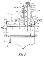
- an oil tank 10 which is formed from metal sheets.
- the oil tank comprises a tank bottom 5, side walls 6 and a tank lid 7 having a cylindrical neck 8, all together forming a housing 11.
- the housing 11 has a baffle plate 12 which defines two substantially upright compartments. These compartments are conveniently referred to as a breather volume, upper region or top compartment 13 and an oil volume, lower region or bottom compartment 14 in the following description.
- the baffle plate 12 carries a plate gauze oil filter element 23.
- the top compartment 13 is provided with an air outlet 15 and a centrifugal de-aerator or gas separator 16.
- the centrifugal de-aerator 16 comprises a non-rotating upright tube or swirl tube which has a tangentially extending oil inlet 17 in order to give a circular flow to the air and oil mixture entering by way of the inlet 17 into the swirl tube 16.
- the swirl tube 16 may be provided with a second oil inlet 17b for oil from a cooler by-pass circuit, according the type of engine.
- the top end of the tube 16a communicates with the top compartment 13 whereas the bottom end of the tube 16b communicates with the bottom compartment 14 by an extending part of the tube 16 that passes through a hole arranged in the plate 12. It will be appreciated that there is no seal between the tube 16 and the plate 12 so that the top compartment 13 can communicate, through a gap 18 in the plate, with the bottom compartment 14.
- the bottom compartment 14 is also provided with an oil outlet 19.
- the cylindrical neck 8 includes an access aperture 20 which is closed in use by a filler cap 21.
- This access aperture 20 permits the use of a conventional dipstick 22 for a visual determination of the oil level within the bottom compartment 14. It will be seen on the drawing (Fig. 3) that the dipstick 21 passes through the centrifugal de-aerator or swirl tube 16 to reach the bottom compartment 14.
- the oil tank 10 as so far described is conventional.
- the tank contains oil in the bottom compartment 14 up to a level between the marks on the dipstick 22.
- oil is drawn from the tank 10 through the oil outlet 19 by a feed pump to lubricate the engine while oil with entrapped air enters the centrifugal de-aerator 16 through the oil inlet 17 and flows in a rotating motion around the interior surface of the swirl tube 16 releasing the air which is allowed to escape out of the top of the tube 16a into the top compartment 13.
- the air is then returned to the engine via the air outlet 15.
- the oil then falls into the bottom compartment 14 to be fed back to the engine.
- each baffle plate 30,31 forming a condensation trap, is substantially V-shaped in cross section and includes a central portion 30a, 31 a which is secured around the swirl tube 16 and a peripheral portion 30b, 31 b which is secured to the tank lid 7.
- each baffle plate 30, 31 forms a collector area for condensation which is funnelled towards the swirl tube 16.
- Each baffle plate 30, 31 includes several apertures 30c, 31c located towards the outer portion 30b, 31 b to act as an overflow preventing each collector area from filling and to allow air and water vapour to escape.
- baffle plates offers the advantage of catching droplets of condensation and conducting them in to contact with the wall of the swirl tube 16.
- the hot oil from the engine maintains the wall of the swirl tube 16 at a temperature which is sufficiently high to vaporise the droplets of condensation which can then escape into the top compartment 13 through the holes 30c, 31 c and then through the air outlet 15.
- most of condensation formed in the oil tank is prevented from reaching the oil, prolonging the life of the oil and, thus, the components of the engine.
Landscapes
- Engineering & Computer Science (AREA)
- General Engineering & Computer Science (AREA)
- Mechanical Engineering (AREA)
- Chemical & Material Sciences (AREA)
- Chemical Kinetics & Catalysis (AREA)
- Lubrication Details And Ventilation Of Internal Combustion Engines (AREA)
- Loading And Unloading Of Fuel Tanks Or Ships (AREA)
Applications Claiming Priority (1)
| Application Number | Priority Date | Filing Date | Title |
|---|---|---|---|
| GB0427371A GB2421284B (en) | 2004-12-15 | 2004-12-15 | Oil tank for dry sump engines |
Publications (3)
| Publication Number | Publication Date |
|---|---|
| EP1672190A2 true EP1672190A2 (fr) | 2006-06-21 |
| EP1672190A3 EP1672190A3 (fr) | 2008-06-04 |
| EP1672190B1 EP1672190B1 (fr) | 2009-09-23 |
Family
ID=34090019
Family Applications (1)
| Application Number | Title | Priority Date | Filing Date |
|---|---|---|---|
| EP05270085A Expired - Lifetime EP1672190B1 (fr) | 2004-12-15 | 2005-11-28 | Réservoir d'huile pour moteur à carter sec |
Country Status (6)
| Country | Link |
|---|---|
| US (1) | US7618482B2 (fr) |
| EP (1) | EP1672190B1 (fr) |
| AT (1) | ATE443803T1 (fr) |
| DE (1) | DE602005016767D1 (fr) |
| ES (1) | ES2334145T3 (fr) |
| GB (1) | GB2421284B (fr) |
Cited By (1)
| Publication number | Priority date | Publication date | Assignee | Title |
|---|---|---|---|---|
| FR2913721A1 (fr) * | 2007-03-13 | 2008-09-19 | Peugeot Citroen Automobiles Sa | Moteur dote d'un guide-jauge integre au conduit de retour d'huile. |
Families Citing this family (9)
| Publication number | Priority date | Publication date | Assignee | Title |
|---|---|---|---|---|
| USD555067S1 (en) * | 2005-12-30 | 2007-11-13 | Aaron Kruger | Oil tank with transparent sides |
| DE102006055285B4 (de) * | 2006-11-23 | 2017-07-06 | Dr. Ing. H.C. F. Porsche Aktiengesellschaft | Ölfilter mit Bypassventil und Ölbehälter |
| US8028672B2 (en) * | 2008-02-27 | 2011-10-04 | GM Global Technology Operations LLC | Dry sump oil tank assembly for a vehicle |
| DE102015120931A1 (de) * | 2015-12-02 | 2017-06-08 | Dr. Ing. H.C. F. Porsche Aktiengesellschaft | Schmiermitteltankanordnung |
| USD820396S1 (en) * | 2017-06-16 | 2018-06-12 | Gary Don Armstrong | Atmospheric vent can |
| GB201807265D0 (en) * | 2018-05-03 | 2018-06-20 | Rolls Royce Plc | Oil tank system |
| CN113694569B (zh) * | 2021-09-17 | 2022-10-18 | 中国北方发动机研究所(天津) | 一种机油箱消泡方法及消泡装置 |
| CN114233475A (zh) * | 2021-12-01 | 2022-03-25 | 贵州永红航空机械有限责任公司 | 一种航空发动机滑油箱 |
| US12590551B1 (en) * | 2024-09-25 | 2026-03-31 | Pratt & Whitney Canada Corp. | Oil tank return for an aircraft engine oil system |
Family Cites Families (7)
| Publication number | Priority date | Publication date | Assignee | Title |
|---|---|---|---|---|
| US2443875A (en) * | 1943-03-13 | 1948-06-22 | Avco Mfg Corp | Lubricating system for engines |
| DE1903295A1 (de) | 1969-01-23 | 1970-08-06 | Porsche Kg | Vorrichtung zum Entschaeumen des Schmiermittels von Brennkraftmaschinen |
| DE1916967B2 (de) * | 1969-04-02 | 1976-09-16 | Daimler-Benz Ag, 7000 Stuttgart | Oelbehaelter fuer eine rotationskolben-brennkraftmaschine |
| US4957517A (en) * | 1989-04-28 | 1990-09-18 | American Standard Inc. | Sound attenuating liquid-gas separator |
| US5271245A (en) * | 1992-08-20 | 1993-12-21 | Ac&R Components, Inc. | Two-stage helical oil separator |
| GB0128958D0 (en) * | 2001-12-03 | 2002-01-23 | Mclaren Cars Nv | Improvements in or relating to oil tanks for dry sump engines |
| DE10219279B4 (de) | 2002-04-30 | 2005-02-24 | Bayerische Motoren Werke Ag | Trenneinrichtung in einem Ölkreislauf eines Kraftfahrzeugs |
-
2004
- 2004-12-15 GB GB0427371A patent/GB2421284B/en not_active Expired - Fee Related
-
2005
- 2005-11-17 US US11/281,309 patent/US7618482B2/en active Active
- 2005-11-28 AT AT05270085T patent/ATE443803T1/de active
- 2005-11-28 DE DE602005016767T patent/DE602005016767D1/de not_active Expired - Lifetime
- 2005-11-28 EP EP05270085A patent/EP1672190B1/fr not_active Expired - Lifetime
- 2005-11-28 ES ES05270085T patent/ES2334145T3/es not_active Expired - Lifetime
Cited By (1)
| Publication number | Priority date | Publication date | Assignee | Title |
|---|---|---|---|---|
| FR2913721A1 (fr) * | 2007-03-13 | 2008-09-19 | Peugeot Citroen Automobiles Sa | Moteur dote d'un guide-jauge integre au conduit de retour d'huile. |
Also Published As
| Publication number | Publication date |
|---|---|
| GB2421284B (en) | 2008-08-20 |
| ATE443803T1 (de) | 2009-10-15 |
| DE602005016767D1 (de) | 2009-11-05 |
| EP1672190A3 (fr) | 2008-06-04 |
| GB2421284A (en) | 2006-06-21 |
| US20060124099A1 (en) | 2006-06-15 |
| GB0427371D0 (en) | 2005-01-19 |
| US7618482B2 (en) | 2009-11-17 |
| EP1672190B1 (fr) | 2009-09-23 |
| ES2334145T3 (es) | 2010-03-05 |
Similar Documents
| Publication | Publication Date | Title |
|---|---|---|
| US5450835A (en) | Oil separator for reducing oil losses from crankcase ventilation | |
| US8028672B2 (en) | Dry sump oil tank assembly for a vehicle | |
| EP1672190B1 (fr) | Réservoir d'huile pour moteur à carter sec | |
| EP1887192B1 (fr) | Séparateur vapeur/liquide | |
| US8272372B2 (en) | Apparatus for treating crankcase gases from engines | |
| CN105804854B (zh) | 在发动机冷却系统中使用的具有离心式空气分离器的除气瓶 | |
| US6350299B1 (en) | Multi-chambered air/oil separator | |
| JPH04227442A (ja) | 凝縮器 | |
| US6033462A (en) | Multi-chambered air/oil separator | |
| US11167237B2 (en) | Air/oil separator | |
| JP2001510524A (ja) | オイルミストセパレータを備えた、内燃機関の潤滑油充填管路 | |
| US5975065A (en) | Venting arrangement for an internal combustion engine | |
| JP3916433B2 (ja) | ブリーザ装置 | |
| US20050092309A1 (en) | Blowby gas separation system | |
| JPH081127B2 (ja) | エンジンのブローバイガス用油分離装置 | |
| WO1998011332A1 (fr) | Ensemble reniflard de carter pour moteur a combustion interne | |
| EP1454038B1 (fr) | Ameliorations de ou relatives a des reservoirs d'huile pour moteurs carter sec | |
| JPH09189212A (ja) | ブリーザ装置 | |
| JP2002097919A (ja) | エンジンのブリーザ装置 | |
| CN210397031U (zh) | 油气分离器及压缩机 | |
| JP4517831B2 (ja) | 内燃機関 | |
| JPS645046Y2 (fr) | ||
| US20240421653A1 (en) | Electric machine for driving a motor vehicle | |
| CN213743588U (zh) | 油气分离器及发动机 | |
| JP2007309157A (ja) | ブローバイガス用オイルセパレータ |
Legal Events
| Date | Code | Title | Description |
|---|---|---|---|
| PUAI | Public reference made under article 153(3) epc to a published international application that has entered the european phase |
Free format text: ORIGINAL CODE: 0009012 |
|
| AK | Designated contracting states |
Kind code of ref document: A2 Designated state(s): AT BE BG CH CY CZ DE DK EE ES FI FR GB GR HU IE IS IT LI LT LU LV MC NL PL PT RO SE SI SK TR |
|
| AX | Request for extension of the european patent |
Extension state: AL BA HR MK YU |
|
| RAP1 | Party data changed (applicant data changed or rights of an application transferred) |
Owner name: ASTON MARTIN LAGONDA LIMITED |
|
| 111Z | Information provided on other rights and legal means of execution |
Free format text: AT BE BG CH CY CZ DE DK EE ES FI FR GB GR HU IE IS IT LT LU LV MC NL PL PT RO SE SI SK TR Effective date: 20071122 |
|
| PUAL | Search report despatched |
Free format text: ORIGINAL CODE: 0009013 |
|
| AK | Designated contracting states |
Kind code of ref document: A3 Designated state(s): AT BE BG CH CY CZ DE DK EE ES FI FR GB GR HU IE IS IT LI LT LU LV MC NL PL PT RO SE SI SK TR |
|
| AX | Request for extension of the european patent |
Extension state: AL BA HR MK YU |
|
| 17P | Request for examination filed |
Effective date: 20081203 |
|
| AKX | Designation fees paid |
Designated state(s): AT BE BG CH CY CZ DE DK EE ES FI FR GB GR HU IE IS IT LI LT LU LV MC NL PL PT RO SE SI SK TR |
|
| GRAP | Despatch of communication of intention to grant a patent |
Free format text: ORIGINAL CODE: EPIDOSNIGR1 |
|
| GRAS | Grant fee paid |
Free format text: ORIGINAL CODE: EPIDOSNIGR3 |
|
| GRAA | (expected) grant |
Free format text: ORIGINAL CODE: 0009210 |
|
| AK | Designated contracting states |
Kind code of ref document: B1 Designated state(s): AT BE BG CH CY CZ DE DK EE ES FI FR GB GR HU IE IS IT LI LT LU LV MC NL PL PT RO SE SI SK TR |
|
| REG | Reference to a national code |
Ref country code: GB Ref legal event code: FG4D |
|
| REG | Reference to a national code |
Ref country code: CH Ref legal event code: EP |
|
| REG | Reference to a national code |
Ref country code: IE Ref legal event code: FG4D |
|
| REF | Corresponds to: |
Ref document number: 602005016767 Country of ref document: DE Date of ref document: 20091105 Kind code of ref document: P |
|
| REG | Reference to a national code |
Ref country code: SE Ref legal event code: TRGR |
|
| PG25 | Lapsed in a contracting state [announced via postgrant information from national office to epo] |
Ref country code: LT Free format text: LAPSE BECAUSE OF FAILURE TO SUBMIT A TRANSLATION OF THE DESCRIPTION OR TO PAY THE FEE WITHIN THE PRESCRIBED TIME-LIMIT Effective date: 20090923 Ref country code: FI Free format text: LAPSE BECAUSE OF FAILURE TO SUBMIT A TRANSLATION OF THE DESCRIPTION OR TO PAY THE FEE WITHIN THE PRESCRIBED TIME-LIMIT Effective date: 20090923 |
|
| LTIE | Lt: invalidation of european patent or patent extension |
Effective date: 20090923 |
|
| PG25 | Lapsed in a contracting state [announced via postgrant information from national office to epo] |
Ref country code: LV Free format text: LAPSE BECAUSE OF FAILURE TO SUBMIT A TRANSLATION OF THE DESCRIPTION OR TO PAY THE FEE WITHIN THE PRESCRIBED TIME-LIMIT Effective date: 20090923 Ref country code: SI Free format text: LAPSE BECAUSE OF FAILURE TO SUBMIT A TRANSLATION OF THE DESCRIPTION OR TO PAY THE FEE WITHIN THE PRESCRIBED TIME-LIMIT Effective date: 20090923 Ref country code: PL Free format text: LAPSE BECAUSE OF FAILURE TO SUBMIT A TRANSLATION OF THE DESCRIPTION OR TO PAY THE FEE WITHIN THE PRESCRIBED TIME-LIMIT Effective date: 20090923 |
|
| NLV1 | Nl: lapsed or annulled due to failure to fulfill the requirements of art. 29p and 29m of the patents act | ||
| REG | Reference to a national code |
Ref country code: ES Ref legal event code: FG2A Ref document number: 2334145 Country of ref document: ES Kind code of ref document: T3 |
|
| PG25 | Lapsed in a contracting state [announced via postgrant information from national office to epo] |
Ref country code: CY Free format text: LAPSE BECAUSE OF FAILURE TO SUBMIT A TRANSLATION OF THE DESCRIPTION OR TO PAY THE FEE WITHIN THE PRESCRIBED TIME-LIMIT Effective date: 20090923 |
|
| PG25 | Lapsed in a contracting state [announced via postgrant information from national office to epo] |
Ref country code: EE Free format text: LAPSE BECAUSE OF FAILURE TO SUBMIT A TRANSLATION OF THE DESCRIPTION OR TO PAY THE FEE WITHIN THE PRESCRIBED TIME-LIMIT Effective date: 20090923 Ref country code: CZ Free format text: LAPSE BECAUSE OF FAILURE TO SUBMIT A TRANSLATION OF THE DESCRIPTION OR TO PAY THE FEE WITHIN THE PRESCRIBED TIME-LIMIT Effective date: 20090923 Ref country code: IS Free format text: LAPSE BECAUSE OF FAILURE TO SUBMIT A TRANSLATION OF THE DESCRIPTION OR TO PAY THE FEE WITHIN THE PRESCRIBED TIME-LIMIT Effective date: 20100123 Ref country code: RO Free format text: LAPSE BECAUSE OF FAILURE TO SUBMIT A TRANSLATION OF THE DESCRIPTION OR TO PAY THE FEE WITHIN THE PRESCRIBED TIME-LIMIT Effective date: 20090923 Ref country code: PT Free format text: LAPSE BECAUSE OF FAILURE TO SUBMIT A TRANSLATION OF THE DESCRIPTION OR TO PAY THE FEE WITHIN THE PRESCRIBED TIME-LIMIT Effective date: 20100125 |
|
| PG25 | Lapsed in a contracting state [announced via postgrant information from national office to epo] |
Ref country code: SK Free format text: LAPSE BECAUSE OF FAILURE TO SUBMIT A TRANSLATION OF THE DESCRIPTION OR TO PAY THE FEE WITHIN THE PRESCRIBED TIME-LIMIT Effective date: 20090923 |
|
| PG25 | Lapsed in a contracting state [announced via postgrant information from national office to epo] |
Ref country code: MC Free format text: LAPSE BECAUSE OF NON-PAYMENT OF DUE FEES Effective date: 20091130 Ref country code: BE Free format text: LAPSE BECAUSE OF FAILURE TO SUBMIT A TRANSLATION OF THE DESCRIPTION OR TO PAY THE FEE WITHIN THE PRESCRIBED TIME-LIMIT Effective date: 20090923 |
|
| REG | Reference to a national code |
Ref country code: CH Ref legal event code: PL |
|
| PG25 | Lapsed in a contracting state [announced via postgrant information from national office to epo] |
Ref country code: NL Free format text: LAPSE BECAUSE OF FAILURE TO SUBMIT A TRANSLATION OF THE DESCRIPTION OR TO PAY THE FEE WITHIN THE PRESCRIBED TIME-LIMIT Effective date: 20090923 Ref country code: DK Free format text: LAPSE BECAUSE OF FAILURE TO SUBMIT A TRANSLATION OF THE DESCRIPTION OR TO PAY THE FEE WITHIN THE PRESCRIBED TIME-LIMIT Effective date: 20090923 |
|
| PLBE | No opposition filed within time limit |
Free format text: ORIGINAL CODE: 0009261 |
|
| STAA | Information on the status of an ep patent application or granted ep patent |
Free format text: STATUS: NO OPPOSITION FILED WITHIN TIME LIMIT |
|
| 26N | No opposition filed |
Effective date: 20100624 |
|
| PG25 | Lapsed in a contracting state [announced via postgrant information from national office to epo] |
Ref country code: IE Free format text: LAPSE BECAUSE OF NON-PAYMENT OF DUE FEES Effective date: 20091128 Ref country code: CH Free format text: LAPSE BECAUSE OF NON-PAYMENT OF DUE FEES Effective date: 20091130 Ref country code: GR Free format text: LAPSE BECAUSE OF FAILURE TO SUBMIT A TRANSLATION OF THE DESCRIPTION OR TO PAY THE FEE WITHIN THE PRESCRIBED TIME-LIMIT Effective date: 20091224 Ref country code: LI Free format text: LAPSE BECAUSE OF NON-PAYMENT OF DUE FEES Effective date: 20091130 |
|
| PGFP | Annual fee paid to national office [announced via postgrant information from national office to epo] |
Ref country code: AT Payment date: 20101110 Year of fee payment: 6 |
|
| PG25 | Lapsed in a contracting state [announced via postgrant information from national office to epo] |
Ref country code: BG Free format text: LAPSE BECAUSE OF FAILURE TO SUBMIT A TRANSLATION OF THE DESCRIPTION OR TO PAY THE FEE WITHIN THE PRESCRIBED TIME-LIMIT Effective date: 20091130 |
|
| PGFP | Annual fee paid to national office [announced via postgrant information from national office to epo] |
Ref country code: SE Payment date: 20101111 Year of fee payment: 6 |
|
| PG25 | Lapsed in a contracting state [announced via postgrant information from national office to epo] |
Ref country code: LU Free format text: LAPSE BECAUSE OF NON-PAYMENT OF DUE FEES Effective date: 20091128 |
|
| PG25 | Lapsed in a contracting state [announced via postgrant information from national office to epo] |
Ref country code: HU Free format text: LAPSE BECAUSE OF FAILURE TO SUBMIT A TRANSLATION OF THE DESCRIPTION OR TO PAY THE FEE WITHIN THE PRESCRIBED TIME-LIMIT Effective date: 20100324 |
|
| PGFP | Annual fee paid to national office [announced via postgrant information from national office to epo] |
Ref country code: ES Payment date: 20101217 Year of fee payment: 6 |
|
| PG25 | Lapsed in a contracting state [announced via postgrant information from national office to epo] |
Ref country code: TR Free format text: LAPSE BECAUSE OF FAILURE TO SUBMIT A TRANSLATION OF THE DESCRIPTION OR TO PAY THE FEE WITHIN THE PRESCRIBED TIME-LIMIT Effective date: 20090923 |
|
| REG | Reference to a national code |
Ref country code: DE Ref legal event code: R082 Ref document number: 602005016767 Country of ref document: DE Representative=s name: MOSER & GOETZE PATENTANWAELTE, DE Ref country code: DE Ref legal event code: R082 Ref document number: 602005016767 Country of ref document: DE Representative=s name: MOSER GOETZE & PARTNER PATENTANWAELTE MBB, DE |
|
| REG | Reference to a national code |
Ref country code: FR Ref legal event code: RG Effective date: 20120227 |
|
| REG | Reference to a national code |
Ref country code: SE Ref legal event code: EUG |
|
| REG | Reference to a national code |
Ref country code: AT Ref legal event code: MM01 Ref document number: 443803 Country of ref document: AT Kind code of ref document: T Effective date: 20111128 |
|
| PG25 | Lapsed in a contracting state [announced via postgrant information from national office to epo] |
Ref country code: SE Free format text: LAPSE BECAUSE OF NON-PAYMENT OF DUE FEES Effective date: 20111129 |
|
| PG25 | Lapsed in a contracting state [announced via postgrant information from national office to epo] |
Ref country code: AT Free format text: LAPSE BECAUSE OF NON-PAYMENT OF DUE FEES Effective date: 20111128 |
|
| REG | Reference to a national code |
Ref country code: ES Ref legal event code: FD2A Effective date: 20130603 |
|
| PG25 | Lapsed in a contracting state [announced via postgrant information from national office to epo] |
Ref country code: ES Free format text: LAPSE BECAUSE OF NON-PAYMENT OF DUE FEES Effective date: 20111129 |
|
| REG | Reference to a national code |
Ref country code: FR Ref legal event code: PLFP Year of fee payment: 11 |
|
| REG | Reference to a national code |
Ref country code: FR Ref legal event code: PLFP Year of fee payment: 12 |
|
| REG | Reference to a national code |
Ref country code: FR Ref legal event code: PLFP Year of fee payment: 13 |
|
| P01 | Opt-out of the competence of the unified patent court (upc) registered |
Effective date: 20230404 |
|
| PGFP | Annual fee paid to national office [announced via postgrant information from national office to epo] |
Ref country code: DE Payment date: 20241108 Year of fee payment: 20 |
|
| PGFP | Annual fee paid to national office [announced via postgrant information from national office to epo] |
Ref country code: GB Payment date: 20241025 Year of fee payment: 20 |
|
| PGFP | Annual fee paid to national office [announced via postgrant information from national office to epo] |
Ref country code: FR Payment date: 20241108 Year of fee payment: 20 |
|
| PGFP | Annual fee paid to national office [announced via postgrant information from national office to epo] |
Ref country code: IT Payment date: 20241115 Year of fee payment: 20 |
|
| REG | Reference to a national code |
Ref country code: DE Ref legal event code: R071 Ref document number: 602005016767 Country of ref document: DE |
|
| REG | Reference to a national code |
Ref country code: GB Ref legal event code: PE20 Expiry date: 20251127 |